Transcription
Tutorial T-2An Overview of Audio SystemGrounding & ShieldingPresented byBill WhitlockPresident, Jensen Transformers, Inc.Member, Audio Engineering SocietySenior Member, Institute of Electrical and Electronic Engineers
So Many Myths Look for MYTH alerts Topic has “BLACK ART” reputation Basic rules of physics are routinelyoverlooked, ignored, or forgotten Manufacturers often clueless – don’t knowground loops from
The Physics Police Rule!
The Electrical Environment Regulations protecting us from electrocutionand fire also play a big role in noise problems NEC or “Code” requires 120-volt ac powerdistribution via a 3-wire system Safety Grounding electrically interconnectsconductive objects to keep voltages betweenthem safe, even if equipment fails Neutral (white) and safety ground (green) arebonded together at service entrance only
What is Grounding? Electrical power: an interconnection ofexposed conductive objects to minimizevoltage differences between them Electronics: a return path for current Current always returns to its sourcewhether via an intentional or accidental path— electrons don’t read schematics!
The 3-wire System One incoming service wires, often bare, is thegrounded or "neutral" conductor NEC requires 120-volt ac power distributionvia the 3-wire system Neutral (white) and “line” (black) are part ofthe normal load circuit Neutral and “grounding” (green) are bondedto each other and to earth ground at serviceentrance
Normal Load Current in Branch Circuit
Deadly Equipment Equipment can become a shock/electrocutionhazard if its internal insulation fails Such a defect can make the entire device“live” at 120 volts and is called a FAULT Without a safety ground, these failures canshock or electrocute people or start fires! Signal cables conduct 120 volts – one FAULTcan turn an entire system into a shock hazard
Don’t Electrocute System Users!!
Shock and Electrocution CURRENT determines severity Under 1 mA causes just an unpleasant “tingling”About 10 mA causes involuntary muscle contractionand “death grip” or suffocation if through chestOver 50 mA through chest can induce ventricularfibrillation – causing brain death minutes later Dry skin has high resistance – keeping currentlow when lightly touching a 120-volt wire Skin moisture, larger contact area, or increasedpressure will substantially increase current Always respect the dangers of electricity!
DON’T BET YOUR LIFE!NEVER, EVER defeat safety grounding tosolve a noise problem!This adapter is intended toPROVIDE safety groundingfor a 2-prong receptacle(via its cover mounting screw,metallic saddle, J-box, andconduit back to breaker box)
GFCI for Safety Ground-fault circuit interrupteror GFCI does not require ground Senses difference between lineand neutral current Difference is current not returning in neutral Presumed to be flowing through a person Trips at 4 to 7 mA GFCI shown has a retractable ground pin Nuisance trips may be a problem
MYTH: Safety Grounds WorkBecause of Earth Grounding Safety ground is bonded to NEUTRALat main entry panel This low-impedance circuit allows highfault current, tripping breaker quickly Earth ground does NOT play a role!
Fault Current Trips Circuit BreakerNOT INVOLVED
Consider Signal Cables Can distribute lethal voltage from “lifted”faulty device throughout entire system, or High fault current may flow through signalcable to reach grounded device, causing fire Defeating safety grounding is both dangerousand illegal — it also makes you legally liable! Judge won’t care how your “fix” solved problem
Typical Statistics for USA Consumer audio/video equipmentcauses 10 electrocutions and 2,000residential fires every year Fires result in 100 civilian injuries, 20deaths, and over 30 million inproperty losses
Earth Ground is for LIGHTNING Power lines become targets of Before Code, power lines literallyguided lightning into buildings! Outdoor power lines grounded at intervals Impedance of ground rod at service entranceis 25 Ω, sufficient to limit lightning damage Protection of phone and CATV lines, wherethey enter building, is also required by Code
Bond Added Ground Rods During actual strike, thousands of voltscan develop between separate rods! Consider computer modem bridging powerand telephone lines Code requires that all other protectivegrounds be bonded to the utility powergrounding electrode
MYTH: Earth Ground Zero Volts NOT with respect to each other or somemystical “absolute” reference point Other nearby ground connectionscreate soil voltage gradients “Those looking for a better earth or betterground to solve a noise problem are lookingfor pie in the sky.” Ralph Morrison
Ground Rod is Useless for Fault CurrentsYIKES!HIGH IMPEDANCE
MYTH: Most Noise is Caused by“Improper” AC Power Wiring Small voltages between outlet safetygrounds is NORMAL in proper wiring Parasitic transformer effects in wiringLowest between nearby outlets on the samebranch circuitHighest (up to a few volts) between distantoutlets on different branch circuits INTERFACE problems cause the NOISE!
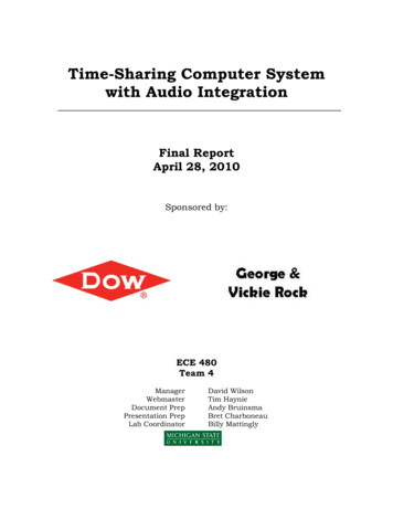
The Parasitic TransformerLoad current magneticallyinduces voltage in groundwiring between outletsCopper Institute
The Parasitic Transformer Load current in line and neutral produceequal but opposing magnetic fields Imperfect cancellation magnetically inducesvoltage in safety ground conductor Highest voltages with loose wires in steel conduit Lower voltages with uniform geometry of Romex 1 volt difference between outlets not unusual Proportional to load current
About 2-prong Plugs UL approval requires extraordinary protection Must remain safe in spite of component failure,overload, and rough handling Chassis voltage can approach 120 volts butcurrent is limited by parasitic capacitances 0.75 mA maximum for consumer electronics This “LEAKAGE” current will flow in signalcables connected to other equipment
Equipment with 2-prong PlugsLEAKAGE current flows in signal cablesbetween devices with 2-prong ac plugs
The Facts Of Life Ground voltage differences will ALWAYSexist between outlets Leakage currents will ALWAYS flow insignal cables COUPLING allows them to enter thesignal path and is the REAL problem!
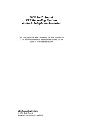
It’s Not Just 60 Hz Many, if not most, loads draw currentnon-uniformly during each cycle Waveform distortion 2% to 6% THD Higher frequencies generated by abruptcurrent changes (as in light dimmers) Power wiring “rings” and reflects energythroughout building
Typical Leakage Current Spectrum
MYTH: These Voltages andCurrents can be Eliminated “SHORT ‘EM OUT” with massive copper bus barsExperiment to find a “better” or “quieter” groundRoute noise to an earth ground where it disappearsMake the electrician fix “his” problemInstall equipment to “purify” the “dirty” ac powerDoes an earth ground really stop noise? Think aboutall the electronics in a 747 .
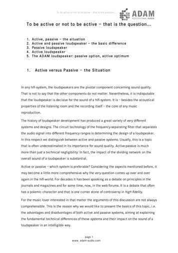
MYTH: Wire “Shorts Out” Voltage DC resistance is directly proportional tolength and applies only at low frequencies 0.015 S for 10 feet of #12 AWG example Inductance is directly proportional to lengthand nearly independent of its diameter 4.8 :H for example (straight) Increases substantially at bends
Wire Impedance vs FrequencyFor comparison, ½-inch copper rod 25 S at 1 MHz
Think “Outside the Box” SIGNALS accumulate NOISE as they flowthrough a system Removing noise without altering/degradingthe signal is essentially impossible Entire signal path must prevent noise coupling Signal INTERFACES are the danger zone,rather than the equipment itself “A cable is a source of potential troubleconnecting two other sources of potentialtrouble.”
What’s an Interface? Signal transport sub-system consisting ofa line DRIVER (output), the LINE orcable, and a line RECEIVER (input) TWO conductors are always required tocomplete a signal (or any) current path
What’s Impedance? The apparent resistance to current flowin an AC circuit – the functionalequivalent of resistance in a DC circuit Symbolized Z and measured in ohms
Balanced and Unbalanced Status depends ONLY on the IMPEDANCES(to ground) of the two signal conductors In unbalanced interface, one line has zeroimpedance (grounded) and other has somehigher impedance In balanced interface, both have nominallyequal impedances Requires that driver, line, and receiver eachmaintain equal impedances
Unbalanced vs Balanced InterfacesGroundedUnbalancedBalanced
Driver & Receiver Impedances Every driver has an internal impedancecalled output impedance, shown as Zo Real outputs can’t have zero output impedance,but lower is better Not to be confused with load impedance!! Every receiver has an internal impedancecalled input impedance, shown as Zi Real inputs can’t have infinite input impedance,but higher is better
MYTH: Impedance Implies Level Signal level, impedance, and balance arecompletely independent of each other: Pro Mic out lo-Z, lo-level, balancedPro Line out lo-Z, hi-level, balancedConsumer/MI Line out lo-Z, hi-level, unbalancedConsumer Mic out lo-Z, lo-level, unbalancedPhono out hi-Z, lo-level, unbalancedGuitar out hi-Z, hi-level, unbalanced
A Signal Voltage Divider Driver and receiver impedances Zo and Ziform series circuit called a voltage divider Voltage drops are proportional to impedance For maximum signal voltage at receiver, Zimust be much greater than Zo Typical audio interfaces transfer 90% to99.9% of the available signal voltage
The Signal Voltage DividerGroundedUnbalancedBalanced
MYTH: Audio Inputs and OutputsShould Be “Impedance Matched” Wastes half the signal voltage and places anunnecessarily heavy load on the driver! Transfers maximum power in vintage passive600 Ω systems but not applicable to modernaudio systems driven by signal voltage Higher frequency cables are terminated withthe “characteristic impedance” of the cable toavoid “transmission line” effects Characteristic impedance is that of an infinitelength of cable and varies with construction
Termination for Video and RF “Transmission line” effects start to becomesignificant when the physical length of a cablebecomes 10% of an electrical wavelength Applies to video cables over a few feet longand CATV cables over a few inches long To avoid video “ghosts,” source and loadimpedances at physical ends must match thecharacteristic impedance of the cable For audio cables, termination is a concernonly when cables are over 4,000 feet long!
UNBALANCED Interfaces EXTREMELY susceptible to noise coupling! Ironic that, after 50 years, they remain the norm inconsumer and audiophile audio, even as dynamicrange requirements have steadily increased Video interfaces (analog) Coupling causes visible “hum bars” RS-232 interfaces Coupling causes “mysterious” problems
The Big Problem Leakage currents flow in signal cables Virtually all in grounded conductor, typicallythe “shield,” whose impedance is not zero Noise voltage generated over its lengthdue to its resistance – Ohm’s Law Noise directly adds to signal seen atreceiver (voltages add in series circuit)
Common-Impedance CouplingIt’s NOT about SHIELDING!
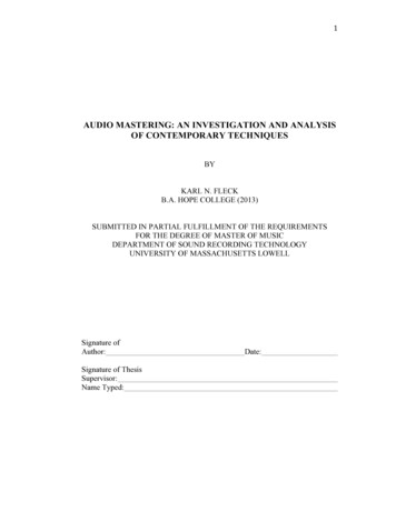
MYTH: Poor Shielding Causes Noise Common-impedance coupling causes 99% ofnoise problems in unbalanced interfaces Trivial noise contributor in modern systems Audiophile cables from famous maker, costing 80 to 500 per 1-meter pair, have no shieldat all — wires are simply woven together! Shielding can be issue with old vacuum-tubeequipment because of high Zo in drivers
A Real-World Example Assume 25-foot, foil-shield cable with #26 AWG drain wire, R 1 SAssume leakage current between 2-prong(ungrounded) devices is 316 µANoise voltage 316 µVConsumer reference 316 mVS/N ratio 316 mV/316 µV only 60 dBBelden #8241F cable, shield R 0.065 S,would improve S/N by some 24 dB!
From Bad to Worse When devices are grounded, often via othersystem cables, noise can become EXTREME! When ground voltage difference of only 30 mVbetween outlets is impressed across length ofcable, resulting S/N becomes only 20 dB Huge problem in home theater systems havingmultiple ground connections – sub-woofers andprojectors with 3-prong plugs, CATV, and satelliteTV connections
Cable ShieldingShields prevent ONLY electric field couplingElectric fields produced by high ac voltagesCapacitance Cc in space to offending sourceAC voltage causes current flow in CcWithout shield, current flows into signal line,creating a noise voltage Grounded shield diverts currents to ground
Electric Field Coupling
Shield “Coverage” Foil is usually 100% (optically opaque) Braided from 85% to 95% because of tinyopenings — usually entirely adequate Problem only for very high-impedance linedrivers – typical of some vacuum-tube gear Trivial issue in the vast majority of systems Well-known maker offers several lines of cables,priced from 80 to 500 per 1-meter pair, whichhave no overall shield — wires are simply woven
Immunity to Magnetic Fields Regardless of cable construction, unbalancedinterfaces can’t fully nullify the effects Effective magnetic shielding, especially atpower frequencies, is very difficult to achieve Only magnetic materials like steel conduitprovide any significant shielding — ordinarycable shielding has no effect More about this later (balanced interfaces)
Physics from Another Universe? Audio, especially "high-end," abounds withpseudo-science and mysticism Double-blind tests prove that audibledifferences among cables, if they actuallyexist, are entirely predictable Marketing hype* often invokes transmissionline theory and implies that nano-second pulserise-times are important Audio cables only begin to exhibit such effectswhen they become about 4,000 feet long!* Hype: enthusi
distribution via a 3-wire system . MYTH: Poor Shielding Causes Noise Common-impedance coupling causes 99% of noise problems in unbalanced interfaces Trivial noise contributor in modern systems Audiophile cables from famous maker, costing 80 to 500 per 1-meter pair, have no shield at all — wires are simply woven together! Shielding can be issue with old vacuum-tube equipment because of .