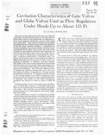
Transcription
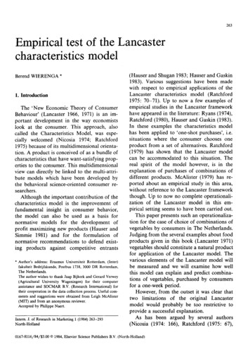
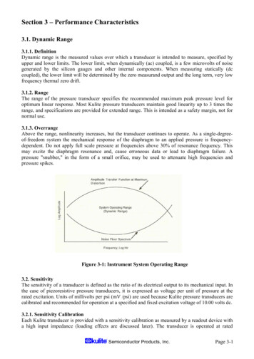
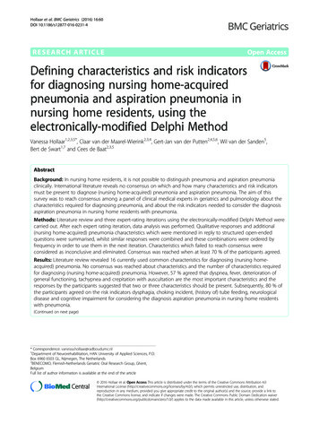
A P 91HYDRAULICS BRANCHOFFICIAL FILE COPY2!Paper No.56—F-10-C LADil NI'UhlCavitation Characteristics of Gate Valvesand Globe Valves Used as Flow RegulatorsUnder Heads Up to About 125 FtBY J. W. BALL,' DENVER, COLO.The series of tests discussed in this paper was made forthe purpose of determining whether or not gate valves orglobe valves could be used satisfactorily for regulating releases from irrigation- distribution systems under headsup to about 125 ft . Both types of valves proved unsuitablefor making free-flow releases because of the wide dispersionof the jets under throttled conditions. Confinement ofthe jets to pipelines downstream induced cavitation in anddownstream of the valves and a study was made of thepressures in the pipelines upstream and downstream of6, 8, 10, and 12-in. gate valves, and a 6-in. globe valve toevolve a means of eliminating or minimizing the cavitation. A pressure relationship or "cavitation index" wasfound to be a useful means of determining the limits ofdifferential head and back pressure to either control thelocation of, minimize, or eliminate cavitation damage.The design of the water passage immediately downstreamfrom the valves and the pressure within this passage werethe two main factors influencing the cavitation characteristics of an installation. One of the most effective meansof eliminating cavitation damage below gate valves wasthe placing of sudden enlargements in the pipe sectionsimmediately downstream. No damage could be detectedin the concrete lining of the sudden enlargement underheads up to 150 ft with back pressures of approximately 15ft, although noise similar to that which accompaniescavitation was present at heads in excess of about 90ft.A limited number of tests were made to study the resistance of rubber - like products to cavitation-erosion andtheir use in protecting the downstream pipe wall againstthis erosion. The conclusion was reached that such protection should not be used except in cases where cavita-tion will be mild.Some consideration was given to venting the area in thetop of the pipe just downstream of the valve, but this wasconsidered objectionable because of the influence of entrained air on flow conditions and measuring devices, particularly propeller meters, placed downstream. Moreover, it was doubtful that air admitted to this region wouldreach all critical zones of local cavitation.The information obtained from the valve investigationis very useful as design criteria for irrigation- distribu-tion systems where valves are used for regulating the releases.NI Head, Hydraulic Structures and Equipment Section, EngineeringLaboratories, Bureau of Reclamation.Contributed by the Hydraulic Division for presentation at theFall Meeting, Denver, Colo., September 10-12, 1956, of THE AMERICAN SOCIETY OF MECHANICAL ENGINEERS.NOTE: Statements and opinions advanced in papers are to beunderstood as individual expressions of their authors and not those ofthe Society. Manuscript received at ASME Headquarters, May 23,1956. Paper No. 56—F-10.THE PROBLEMS LAND aid water resources of the Western UnitedStates become more fully utilized, closed-conduit distribution systems are used more extensively to conservethe water which would be lost by seepage and evaporation fromopen-earthen-ditch systems. Usually these closed systems havebeen designed to operate at pressures not to exceed about 50 ftofwater, but in recent years they have been planned for morethan double this pressure. The use of higher pressures posedseveral problems, tot in particular being concerned with cavitation.Two general types of valves were considered, the irrigationand waterworks gate valves and the globe valve. The wide dispersion of the jets below these valves indicated that confinementof the jets would be necessary, Figs. 1 and 2. The necessity ofconfining the jets below the valves introduced problems involving cavitation and vibration. When valves are operated at par-tial openings, low-pressure zones form in the fluid in and downstream of the valves and at the edges of gate-valve recesses.Under certain differential heads these pressures reach the vaporpressure of water and cavitation with vibration is induced.The pressure conditions are influenced by the back pressure on thevalve and the conditions of flow surrounding the jet, the latterbeing influenced by the shape of the flow passages immediatelydownstream of the valves. A cavitation number or index containing the upstream and downstream pressures and the differential head was used to analyze the cavitation characteristicsand evolve criteria for the design of regulating valves installed indistribution systems.High heads and long pipelines made it important that the flowthrough the regulating valves not be shut off suddenly; also,that the cavitation tendencies be reduced to a minimum. Aspecial valve was designed to meet these conditions.TEST PROCEDUREThe valves were placed in settings with several diameterslength of pipe upstream attached to the laboratory supply systemand several diameters length of pipe downstream. The downstream pipe contained another valve for regulating the backpressure on the test valve and a 45-deg downpipe to return theflow to the laboratory supply system, Fig. 3. This downstreamsection was removed for free-discharge tests.Piezometers were placed at points upstream and downstreamof the test valves for investigating pressure distribution, determining the head, and indicating the head losses. Water measuredby venturi meters was supplied to the test valves by two 12-in.centrifugal pumps in series. Test data for all valves wererecorded for various valve openings and discharges. Testvalves were obtained on loan from several manufacturers. Onlytwo valves were installed in concrete pipe to represent actualfield installations.Pressures in the conduit upstream, downstream, and in some ofthe valves were obtained for various discharges and openings.Discussion on this paper will be accepted at ASM E Headquarters until Oct. 15, 1956
TRANSACTIONS OF THE ASMEFIG. 1 JET FROM HUB-END GATE VALVE 171/8 PER CENT OPEN WITH5-FT HEAD6.1 CFs FREE DISCHARGE UNDER 125FIG. 2Cavitation-index values were computed from these data. Sections of concrete-lined pipe were placed at various distances downstream of a standard 6-in. gate valve to determine the location ofcavitation-erosion for various back-pressure conditions. Asection of 12-in. concrete pipe was placed below a 12-in. hub-endgate valve for one cavitation test. An 8-in. valve with a 14-in.tee section placed immediately downstream was tested to evaluate the influence of a sudden enlargement on cavitation. Protective lining materials for pipe sections immediately downstream of the valves. were tested in special Venturi and magnetostriction-oscillator cavitation equipment.CAVITATION CHARACTERISTICS OF GATE VALVESWhen a gate valve in a conduit is. partially open and a highvelocity jet of water passes through the opening, a low-pressurezone is formed in the fluid downstream from the leaf. Low-pressure zones also form downstream from irregularities in the flowboundary such as the downstream edge of the leaf recess noted bythe area marked X in Fig. 3. The pressures in these zones areinfluenced by the differential head across the valve and thedownstream. pressure; thus it was considered possible to determine the permissible head differential for a given back pressure,or the back pressure required to prevent cavitation in theselow-pressure zones (keep the pressure in the zones above the vaporpressure of the water). This could best be accomplished byusing some form of cavitation number or index. Several plots ofpressure data were made before an appropriate index was discovered.JET FROM GLOBE VALVE, FULLY OPEN WITH 4.30 CFs FREEDISCHARGE UNDER 63-FT HEAD.PIEZOMETERS,-TEST VALVE I ,-PIEZOMETERSi vow-2d-r K---------12dStation o'4Station dsFIG. 3 VALVE TEST ARRANGEMENTThe cavitation index in this case is similar to that normallyused to define flow conditions where cavitation is concerned.The numerator is identical with that normally used, assuming theterms apply, to conditions in the cavitation zone, and the denominator is the pressure drop, or head, creating velocity inthe cavitation zone, assuming no loss has occurred ahead of thecavitation zone.Plots of K against discharge coefficients C for different gateopenings revealed that the coefficient was constant when therewas no cavitation in the system and that it decreased as cavitation developed by an increase in differential head. These plotsoffered a means of indicating the conditions for incipient cavitation or for determining the critical cavitation index (K;). Thecoefficient used in this case was that given in the expressionQ CA-\/(2yH)whereThe relationship used wasQ flow quantity, cfsA nominal area of pipe, sq ftH, — Hg acceleration of gravitywhere--K dimensionless number-cavitation indexH2 pressure head in pipe 12 pipe diameters below valveH vapor pressure relative to atmospheric pressure (negative)Hi total head (pressure plus velocity) 2 pipe diameters up-stream of the valveH differentiaf head on valve in feet measured betweenstations 2 pipe diameters upstream and 12 pipe diametersdownstream of valveC coefficient of dischargeThe first attempts to establish critical values of K based onaudible cavitation were made from plots of the data for givenopenings by taking those values of K at the intersection of two
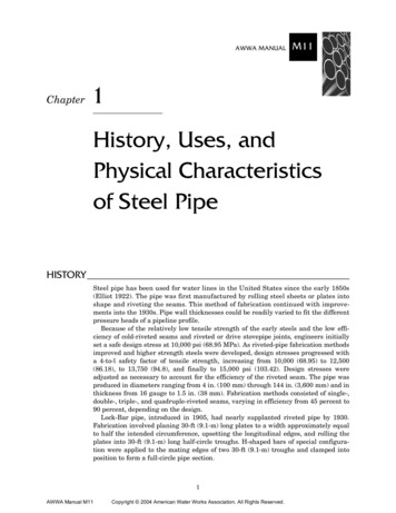
BALL—CAVITATION CHARACTERISTICS OF GATE VALVES AND GLOBE VALVESu 1.020a111.000m Cc .980Qo,960 8Bm.940N .920c v. C4.1111.900g .88011U IU.880- 84001.0-A section of 12-in, pipe with a neopreneSolid symbol Cavitation audible3.0H2- HyH22H Pressurehead 12 dia. downstreamK HTHv Vapor pressure relative to atmospheric pressureHT - Total head 2 dia. upstreamFIG. 42.0m0 6" Std. waterworks valve, 15% opena 6" Std, waterworks valve, 20 % opena 6" Std, waterworks valve, 30% open 8" Bellmouth valve, 30% openw 8" Bellmouth valve, 40% openm 10"Std. waterworks valve, 20% opena 10" Std, waterworks valve, 30% open0 10" Irrigation-type valve, 10% openv 10" irrigation-type valve, 20% openId 10"Irrigation-type valve, 25% openX7 10"Irrigation-type valve, 40% openr 8" Std. waterworks valve with T, 15% open4 8" Std. waterworks valve with T, 20% open0 8 Sfd, waterworks valve with T, 25% openo D d;was considered as one means of permittingthe use of gate valves as flow regulatorswith low back pressures. The alteration ofthe flow passage to form a sudden enlargement immediately downstream of thevalve seemed to offer another possiblesolution . Some idea as to the nature, location, and extent of damage caused by cavitation was needed to evaluate these possibilities. Tests were performed for this purpose by using rubber-lined and concretelined pipe sections below the valves andspecial specimens of rubber material vulcanized to metal shapes in special cavitationtesting facilities.ab -'v,4.0CAVITATION INDEX FOR GATE VALVESlines on the plots, as shown in Fig. 4. One line (a) representedthe average discharge coefficient for the valve opening withoutcavitation, and the other, a sloping line (b), represented theaverage for the points where cavitation was definitely audible.The initial analysis gave a maximum value of Ki of about unitywhich appeared to be about the same for all valve openings.However, further analysis, using additional data, showed a decrease in efficiency at values of K higher than those for whichaudible cavitation was noted. In some cases this critical Valle ofK seemed to be near 2.0. The coefficient for any conditiondivided by the coefficient where there is no cavitation was usedto generalize the data for all valves and openings, Fig: 4.The cavitation-index equation was investigated assuming general cavitation to occur in the pipe immediately downstream of thevalve leaf, and a loss from the gate to the recovery pressuredownstream equal to the Borda loss expressed by HL (VG —V,)2 12g, where VG velocity under gate and VP velocity inpipe downstream. This was done to determine whether or not thecavitation influencing the efficiency of the system was of a generalnature and downstream of the leaf. An evaluation of the criticalcavitation-index values for various gate openings showed an increase with increase in opening until the valve was about 65 per centopen then a decrease with larger opening, Fig. 5. From this curveit appears that the critical value of the cavitation index shouldreach a maximum at about 65 per cent valve opening. Whileis about 1.0 for this case, a value somewhat differentthe Ki-valuemight be expected, depending upon where the downstream pressuure is measured and whether or not the data are referred to acommon base. Local regions of cavitation also might be an influencing factor. This seems to be the case for gate valves because the value of K; at all conditions tested is much greater thanindicated by the curve for general cavitation, Fig. 5.A comparison of the curve for general cavitation conditions,with points based on the data of Fig. 4, indicates the presence oflocal regions of cavitation.The graphs for the tests made thus far had disclosed that cavitation was present to some degree at all values of K below approximately 2.0, that cavitation was present in mild form forvalues of K greater than about 1.0, and that the intensity andseverity of cavitation increased with decreasing values of Kbelow 1.0. These results seemed to offer a source of design criteriaso studies were made to further define the limitations.Protection of the flow-passage surfaces attacked by cavitationlining vulcanized in it was placed down6.05.0stream from a 12-in. irrigation-type gatevalve. The intensity of the cavitationobtained in this arrangement was notsufficient to provide any visual evidenceof damage after many hours of operation,so some means of accelerating the testswas sought. Metal blocks with specimensof 1/16, '/s, and a/Irin. lining vulcanized t
FIG. 1 JET FROM HUB-END GATE VALVE 171/8 PER CENT OPEN WITH 6.1 CFs FREE DISCHARGE UNDER 1255-FT HEAD Cavitation-index values were computed from these data. Sec-tions of concrete-lined pipe were placed at various distances down-stream of a standard 6-in. gate valve to determine the location of cavitation-erosion for various back-pressure conditions. A