Transcription
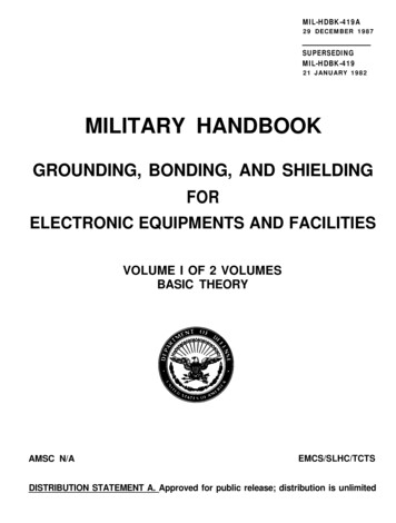
Grounding and Shielding Techniques for LargeScale ExperimentsMarvin Johnson, FermilabAbstract-- The D0 detector has shown excellent commonmode noise performance across all sub detectors. This talkwill describe the detector, the noise performance and themethods that we used to achieve them. I will focus on thegeneral principals rather than the specific implementations. Iwill also discuss some new work that we are doing with carbonfiber composites.INTRODUCTIONhe D0 detector is a large, multipurpose colliding beamsdetector at Fermilab. Fig. 1 shows the main parts of thedetector. This talk will concentrate on the calorimeter andthe silicon detector. The calorimeter is a precision analogdevice with 15 bit resolution ADC’s and the silicon detectorhas severe constraints on mass so many conventional noisereduction methods are difficult to apply.The D0 calorimeter is a large liquid argon calorimeterconsisting of 3 independent cryostats. Each cryostat is about6 meters in diameter, 3 meters in length and contains roughly16,000 channels. The preamps are located on top of eachcryostat and send single ended signals about 15 meters to acounting house located under the detector. Here a correlateddouble sample measurement is made and the difference issent to a second counting house about 60 meters away. Atthis point he signals are digitized in VME crates to 15effective bits. Common mode noise was measured bycomputing a correlation coefficient over 4096 channels andno measurable noise has been found. This gives an upperlimit on the common mode noise of 1 part in 217 or about106 db down from the maximum signal.The D0 silicon system is a fairly conventional silicondetector with a mix of single and double-sided detectors.There are 912 ladders in the detector with around 800,000channels. Readout is via the SVX 2 chip. The commonmode noise is measurable and it is around 1000 electrons Thedetector capacitance is 12 pF so this is a10 µV signal. Thesource of this noise is not yet known.How do we achieve such good noise performance on adetector that weighs 5600 tons and occupies a volume of1700 cubic meters? There are only a few broad principlesinvolved in effective low noise design. It is merely a matterof applying these principles and paying attention to theI.TWork supported by the U.S. Department of Energy under contract No.DE-AC02-76CH03000details. Books by Ott[1] and Morrison [2] are goodreferences for noise reduction techniques.The next section will describe some general principals forlow noise design and the following sections will giveexamples from the D0 detector.II. ELEMENTS OF A LOW NOISE DESIGN.The most important principle is that current follows thepath of least impedance. The key here is impedance whichinvolves inductance and capacitance as well as resistance.Inductance is often overlooked and is very important.Consider a simple structure consisting of two 1 cm diameterrods that are 1 meter long and spaced 1 cm apart. At 30MHz, the impedance from the inductance of one rod equalsthe impedance from the capacitance between the two rods.Thus, if one rod were part of a noisy ground and the otherpart of a precision instrument (silicon detector for example),potentially half the noise would be transferred to the cleansystem. Of course, this depends on the impedances of therest of the circuit but it is quite unlikely that no noise istransferred.The formula for the capacitance of a parallel plate capacitorisC 8.85 10-12eAdwhere A is the area of the plates, d is the separation of theplates and e is the relative permittivity of the materialbetween the plates† ( e 1 for air). The formula for the selfinductance of a straight, round wire is[3]È † Ê 2s ˆ 3 L 2 10-7 smÍLoge Á -† Ë r 4 Ά
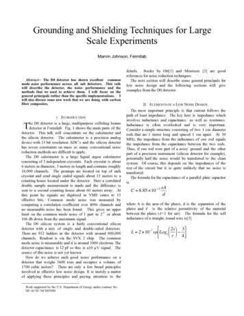
mlineShielding20 mElectronicsFigure 1. Side view of the D0 detector showing the main sub detectors. The platform area is under the detector where the electronics islocated. The ground plane is on the floor of the electronics area.where s and r are the length and radius of the wire and µ is herelative permeability of the material. All units are in SI. Forrectangles an approximate formula isÈÊ 2s ˆ 1 L 2 10-7 smÍLoge Á Ë b c 2 Îwhere b and c are the width and length of the rectangle.Wide, thin sheets have much lower inductance than round orsquare objects †The second principle is that current always flows incomplete circuits. Whenever analyzing a system, one needsto find the complete path and all the paths. An area wherethis is often overlooked is in front end designs where peopleworry a great deal about the path between the detector and thepreamp but ignore completely the ground current path back tothe detector. For example, in a proportional wire chamber,the preamp amplifies the signal between the cathode and theanode and is usually attached to the anode. There must be aa low impedance path from the preamp ground to thecathode. If this is overlooked, the return current may have togo all the way to the high voltage supply and back again. Ifthe path length is long enough, the added phase shift couldcause the preamp to oscillate. Any unnecessarily added pathincreases the likelihood of noise pick up and should beavoided.The third principle can be thought of as a property ofinductance or that nature seeks the minimum energy state. Iwill explain it using inductance. Since the inductance of acircuit is in general proportional to the area enclosed by thecircuit, as the frequency increases, the current will flow in thecircuit with the least area. Typically frequencies for this tooccur begin in the few hundred KHz range. This means thatthere may be a good ground plane between two points, but ifthe signal flows some distance from the ground plane, thereturn current may not be in the ground plane at all.The fourth and last principle is that if one has a set ofcoaxial conductors, any current flowing in the coaxial outershell will be induced in the inner conductors by transformeraction. The inner conductors can be anywhere inside theshell – they do not have to be coaxial. This principle isstrictly true only for round outer conductors but it is a goodapproximation for many common structures such as cabletrays.Another point which is not a general principle but is oftenuseful in practice is that a noise source is usually not avoltage source. That is, it cannot supply an infinite amountof current. Often a simple filters will do a good job ofeliminating noise by loading down the noise source.In applying these principles, the goal is to shunt the noiseaway from the signal carrying conductors. The next sectiondescribes how we applied these principles to achieve the goodnoise performance in D0.
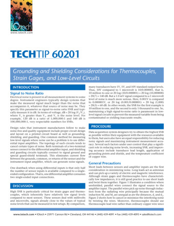
III. EXAMPLES FROM D0.FaradayShi el dA. AC Power DistributionPower distribution plays a very important role in detectordesign. It is best to put in a separate substation for detectorpower. High frequency power does not flow readily throughthe inductance of a transformer coil. However, in order to gethigh power efficiency, transformer makers position theprimary and secondary coils close together so there is a largecapacitive coupling both within and between the primary andsecondary coils. We usually don’t care about capacitiveshorts within the primary or secondary since they just shuntthe power to their respective grounds. However, capacitiveshorts between the two cause unwanted noise transfer.Transformer makers know all about this and they maketransformers with single and double faraday shields. Adouble faraday shield encloses each coil in a metal box(usually copper mesh to avoid large eddy currents). Theprimary shield is then connected to the outside world groundso that incoming noise on the power cables flows back to anexternal ground. Similarly, the secondary shield is connectedto the secondary ground. This keeps any locally generatednoise confined to that system. A single faraday shield hasjust one metal box – usually around the primary.D0 has two 1.5 MVA substations to power the D0complex. One of the substations is mostly dedicated todetector power and the other for everything else. These arenot faraday shielded transformers so the isolation is not large.However, the cables from the substation to the detectortransformers are of order 100 meters so there is some filteringfrom the cable inductance. Cable inductance filtering isdiscussed more fully in the section on magnet powersupplies.D0 employs six 150 KVA transformers to power theexperiment. These were meant to be double faraday shieldedones but, due to a vendor error, there is only a single faradayshield. Fig. 2 shows the transformer configuration that wedesigned for D0. The actual system differs only beremoving the secondary faraday shield.Three of these faraday shielded secondary transformers arelocated in a small counting house located directly below thedetector (called the “platform”) and 3 are located on acounting house outside the radiation wall (called the “movingcounting house”). No attempt is made to isolate functionson the platform. The first two floors of the moving countinghouse are dedicated to digital electronics while the third flooris used for analog readout.There is one transformer per floor of the counting houseand all power for the floor including such things as lightsand air conditioning comes from this transformer. Thisallows a fairly clean separation of power. Of course, thebuilding shares a common ground but we observe that theanalog floor has very little noise from the 2 digital floors.D0 Desi gnFaradayShi el d3 phase I n3 phase outneutr alneutr alBui l di ngGr oundDetectorGr oundSatur abl ei nductorFigure 2 Diagram of a double faraday shielded transformer that wasplanned for D0. The as built design has no secondary shieldD0 has also totally isolated the detector from buildingground for high frequency signals. That is, there is no directconnection for high frequencies between building ground anddetector ground. All signals are either optical or transformerisolated. Of course, there must be a safety ground so that noone is injured if there is a transformer failure. This isprovided by a saturable inductor which is connected betweenthe 2 grounds. The inductor has about 1 mH inductance atlow currents. It starts to saturate at 10 amps and has only80 µH of inductance at full saturation. D0 employs 2 ofthese inductors for redundancy. With these inductors open,the detector has about 45 nF of capacitance to the buildingground. This is about 7 ohms at 500 KHz. We have madeconsiderable effort to maintain this isolation but I think thatit is no longer completely isolated. Even if it is not trulyisolated, the paths for ground currents from the acceleratortunnel to pass through the detector to the D0 complex arevery limited and this removes another potential source ofnoise.B. Magnet Power SuppliesMagnet power supplies are often filtered with series L anda parallel C. This works well for 720 Hz but not for highfrequencies. Again, the turn to turn capacitance in a large,high current inductor shorts out the inductance. D0 hasemployed 2 different methods for high frequency filters forthe magnets. The first utilizes the magnet buss itself. Thepath from the power supply to the detector is about 100meters so the buss has an inductance of about 1.5 mH.Attaching large, oil filled capacitors at the midpoint of thebuss and next to the detector on both the supply and returnlines eliminated almost all of the power supply noise. Notethat there is no specific return path to the power supply forthis high frequency power. The building is made of concreteand steel with a great deal of steel reinforcing rod in theconcrete. We connected the ground of the filter capacitors tothe building ground and attached the power supply to thebuilding steel with a low inductance path.For D0’s superconducting solenoid, we went to a moreconventional air core coil arrangement. The turns are widelyseparated so that the turn to turn capacitance is small andthere is no core to capacitively short out the turns. This
magnet has been in use for the past year and we have noindication of any noise from it.During installation, wemade provision to use the buss filtering method but, so far,it has not been needed.C. Low Voltage Power SuppliesConventional wisdom indicates that linear supplies givethe best low noise performance. Initially, D0 went thisroute. We developed a custom 3 phase linear supply withexcellent noise performance. Unfortunately, its efficiencywas just over 50% and we had to do all the work of buildingand maintaining them. We wanted to try some commercialswitching supplies but did not know what a reasonable set ofspecifications would be. So, we hired a firm that measuresthe noise parameters for commercial manufacturers to measuresome of our linear supplies. We then selected commercialsupplies that exceeded these specs and we have not had anyproblem so far.D. Ground Planes and Ground Reference.Ground planes are usually an essential element of a highperformance circuit board. They provide a reference for singleended signals and act as a low impedance return to the sourcefor noise power generated on the board. They also providesome level of shielding between circuit sections. These samefunctions are needed on a detector. Like designing a board, itis important to determine the ground references for yourdetector at the early design stage. At optimum choice canoften lead to very low noise systems.As mentioned earlier, the output of the calorimeterpreamps is single ended. We need to add many channelstogether to get the energy in a jet of particles so it isimportant that no noise current flow on the ground wire fromeach calorimeter output. We used several methods to achievethis. One of them is to reduce the ground voltage as much aspossible between the preamps and the electronics under thedetector by connecting everything to a low inductance groundplane.We chose the floor of the platform under t
Grounding and Shielding Techniques for Large Scale Experiments Marvin Johnson, Fermilab T. where s and r are the length and radius of the wire and µ is he relative permeability of the material. All units are in SI. For rectangles an approximate formula is † L 2 10-7smLog e 2s b c Ê Ë Á ˆ 1 2 È Î Í where b and c are the width and length of the rectangle. Wide, thin .