Transcription
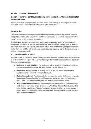
Concrete mix design for X-and gamma shieldingMohamad Pauzi Ismail, Noor Azreen Masenwat, Suhairy Sani, Abdul Bakhri Muhammad, MohdKamal Shah Shamsuddin and Rahmad Abd RashidNDT group, Nuclear MalaysiaAbstractThe design of X-ray or gamma ray radiographic exposure room requires some calculations onshielding to provide safe operation of the facility and minimum exposure to radiation workers.Careful design can lead to economical installations with minimal barriers. The design depends onsuch factors as: maximum energy, maximum intensity, permitted full-body dosage, workload, usefactor, occupancy factor, maximum dose output and shielding materials.Choice of material for a barrier depends on convenience and cost. The radiographic exposure roomis usually made of normal concrete with density of about 2.3 - 2.4 g/cc. Normal concrete is oftenused for construction of exposure room because of cheap and ease of construction.This paper explained and discussed the optimum mix design for normal concrete used for X-andgamma shielding.IntroductionAll works with radiation sources involved a risk of exposure to radiation, which is known asoccupational exposure. However, as a general rule, all workers must take efforts to ensure that theexposure he received is kept to a minimum possible. This is known as ‘As Low As ReasonablyAchievable' (ALARA) concept. For industrial radiography, only external radiation exposure is to beconsidered. If a radioactive material gets inside the human body it gives rise to an internal radiationexposure, which required quite different method of control. The external radiation exposure iscontrolled by applying the three radiation safety principles namely: Working time, Distance andShieldingRadiation exposure received by a radiation worker in radiation area is directly proportional to lengthof time that the individual spends in that area. Limiting the time spent in a radiation area is one ofthe main methods to reduce the amount of radiation exposure received by a radiographer. In reality,this can be achieved by proper planning of the job to be carried out and at the same time distributingthe work evenly among radiographers involved.Maximizing distance from a radiation source is a very effective means of protecting radiographer.This is because radiation exposure decreases drastically with increasing working distance from thesource. The third method of controlling external radiation exposure is by placing a shielding betweenthe source and the radiographer. Shielding could be made of any suitable materials and is placed asa barrier between the radiation source and workers. In practice, lead and concrete are used as
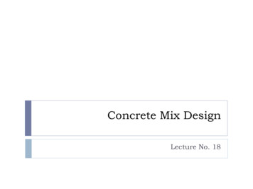
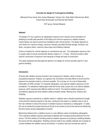
common shielding materials for x- and gamma rays, while water, wax, boron and concrete are usedfor neutrons.Shielding effectiveness for each material depends on its atomic number, density and thickness. It isalso dependent on the energy of radiations. Higher energies of radiations are less likely to interactwith electrons. Thus, they are more penetrating.Concrete as a shielding materialThe depth of penetration for a given photon energy is dependent upon the material density (atomicstructure). The more subatomic particles in a material (higher Z number), the greater the likelihoodthat interactions will occur and the radiation will lose its energy. Therefore, the denser a material isthe smaller the depth of radiation penetration will be. Materials such as depleted uranium, tungstenand lead have high Z numbers, and are therefore very effective in shielding radiation. Concrete isnot as effective in shielding radiation but it is a very common building material and so it is commonlyused in the construction of radiation vaults.Most designers and builders today are familiar with the advantages of using very high densityconcretes for radiation shielding. Not so well known is the excellent economy which can result fromthe use of normal site cast concretes with locally available aggregates when space and other factorsdo not absolutely demand that the desired protection be achieved within minimum dimensionallimits. The effectiveness of any biological shielding material is related only to its mass and concretehas an obvious advantage in this highly specialized field of construction because of its exceptionallylow cost per pound. Lead is an ideal shielding material where thinness alone is a dominantconsideration but it is far more expensive and has poorer structural properties than does concrete.Structure of concreteConcrete is a composite material composed of coarse granular material ( the aggregate or filler)embedded in a hard matrix of material ( the cement or binder) that fills the space between theaggregate particles and glued them together. Aggregates can be obtained from many kinds ofmaterials, although we mostly use of the material of nature- common rock. Aggregates should beinert and act as filler materials. For simplification, aggregate can be classified as fine and coarseaggregates.Cement can be formulated from many diverse chemicals. "Cement” is a generic term that can beapply to all binders. In civil engineering, the binders are Portland cement, calcium aluminate cementor epoxy resin. In concrete construction, most concrete used Portland cement as a binding material.Photograph 1 shows that the cross section of concrete sample which uses granite as coarseaggregate.
Photo 1: Cross-section of concrete sample (2.5X)Setting of ConcreteThe chemical composition of Portland cement consists of 50% tricalcium silicate (C3S), 25%dicalcium silicate (C2S), 12% tricalcium aluminate (C3A), 8% tetracalcium aluminoferrite (C4AF)and 3.5% calcium sulfate dihydrate (CSH2) or called as gypsum (Mindness 1981). Setting ofPortland cement starts from hydration process between water and the surface of particles C3A toform hydrated calcium silicate to give initial strength of the cement. C3S becomes a gel in a fewhours after setting and after 14 days the quantity of gel formation during this setting will influence theinitial strength of concrete. Hydration of C2S ( and also hydrationC3S) which occur slowly willcontribute to 14 and 28 day strength and the strength after 28 days.Concrete Mix DesignConcrete mix design can be defined as a process of selection of material quantity in concrete. Thepurpose is to produce a concrete not only cheap but also meet the intended strength and durability.In mix design process, the following factors have to be considered;a)b)c)d)minimum compressive strength required,water to cement ratiotype of cementdurabilitye)f)g)h)workability and water contentchoice of aggregatecement contentaggregate content
Compressive strengthCompressive strength determined from concrete cube test is the important measurement toevaluate the intended quality of concrete. This compressive strength is tested when the concretecube reach the age of 7 days and 28 days. The minimum cube compressive strength specified bystructural designer at 28 days determined the grade of concrete. Table 1 shows the grade ofconcrete in construction.Table 1:Concrete Grade in ConstructionGrade No.7 101520 253040 6070 100ApplicationConcrete w ithout reinforcementLightweight concreteNormal concretePost stressed concretePre-stressed concreteHigh performance concreteWeight proportion methodThe mix design method can be classified into three methods; Fix method (CP110:1972 ), weight proportionmethod (JKR) and mix design method (Department of environmental UK, DoE method and AmericanConcrete Institute, ACI method).JKR method is used in designing mix for normal concrete of radiation shielding (Table 2). For example, 1:2:4means 1 proportion of cement, 2 proportion of sand and 4 proportion of coarse aggregate by weight.Table 2: JKR methodName of mixMin. Compressive7 days20171481:1:21: 1.5:31:2:41:3:6Strength (N/mm2)28 days3025.52112.5Max aggr. Size20202025 or 38Min. Cem ent (kg/m3)380361321-In this experiment, mixes as in Table 3 were used to obtain the maximum density of concrete. In allmixed water /cement ratio of 0.5 -0.7 is used and adjusted to satisfy the medium slump.Table 3: Design mix for obtaining high densityCD:2.2: 2.5 3:Mix1 1:21 1.5:31 2:3.31111 3:6Mix Cement (kg)10101010101010River sand (kg)10152020263030Crushed granite (kg)20303340294060
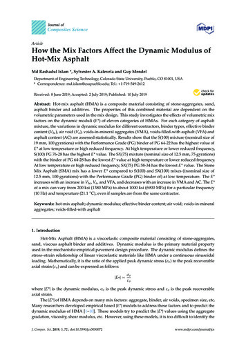
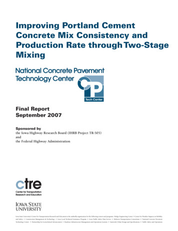
Results and discussionFig. 1 shows data of mix proportion versus density of concrete. As the amount of coarse aggregateis increased, the density will increase. However there is a limit as too much coarse aggregate makemore difficult to compact the concrete and result in lower density. Too rich the cement content alsowill reduce the density. Therefore it is found that mix 1;2:4 is producing highest density for normalconcrete.Similar pattern can be observed for mix proportion versus strength. However the high amount ofcement increases the strength more pronounce than the 240024502500Density (kg/m3)Fig. 1: M ix proportion vs densityConclusionThe optimum mix proportion to produce concrete density of 2300 - 2400 kg/m3 is 1:2:4. The waterto cement ratio is maintained between 0.5 and 0.55 to produce moderate slump and workability.
02530354045Ce mpressivre strengt h (N/ mm 2)Fig. 2: Mix proportion vs. strengthAcknowledgmentThe first author would like to thank to Research and Innovation Management Centre for providingfund to this project (PSI-11-5).References1-2345-6-ANSI/HPS N43.3-2008, American National Standard For General Radiation Safety Installations Using Non-Medical X-Ray and Sealed Gamma-Ray Sources, Energies Up to10 tyCollege/RadiationSafety/safe ielding tcm45-344093.pdfLEM/TEK/33 Rev. 1, 02 December 2008, Code of Practice on Radiation Protection inIndustrial Radiography.Mohamad Pauzi Ismail, 2002, Training Course notes for IAEA Regional Training Course onNon-Destructive Testing Of Concrete in Structures, Beirut, Lebanon, 15-19 April 2002 andDamascus, Syria, 20-25 April 2002.Radiation Safety For Industrial Radiography, Malaysian Nuclear Agency, 2004.
common shielding materials for x- and gamma rays, while water, wax, boron and concrete are used for neutrons. Shielding effectiveness for each material depends on its atomic number, density and thickness.