Transcription
ISSN 2311-6706e-ISSN 2150-5551CN 31-2103/TBARTICLECite asNano-Micro Lett.(2021) 13:200Received: 30 April 2021Accepted: 13 July 2021Published online: 22 September 2021 The Author(s) ompatible Multifunctional E‑Skinswith Excellent Self‑Healing Ability Enabled by Cleanand Scalable FabricationXiuzhu Lin1, Fan Li1, Yu Bing1, Teng Fei1, Sen Liu1, Hongran Zhao1 *, Tong Zhang1 *HIGHLIGHTS A printable multifunctional electronic skin (e-skin) with an excellent self-healing ability was developed via a simple, clean anduniversally applicable method. Water served as both the only solvent throughout the fabrication process and the trigger of the self-healing process. Each e-skincomponent was biocompatible. Combined with conventional electronics, signals collected by the e-skin could be transmitted to smartphones via Bluetooth for postprocessing.ABSTRACT Electronic skins (e-skins) with an excellent sensingand scalability have become new limitations. Self-healing ability canimprove the long-term robustness and reliability of e-skins. However,structures of self-healable devices. Here, cellulose nanofiber/poly(vinylalcohol) (CNF/PVA), a biocompatible moisture-inspired self-healablecomposite, was applied both as the binder in functional layers and thesubstrate. Various functional layers comprising particular carbon mate-Drop & DryidityHumCNF/PVA terategr tionInself-healing ability and integration are hardly balanced in classicalCNFPVATemSeSu lf-hbs ealtra ingteHowever, wearability, biocompatibility, environmental friendlinesstureperaperformance have been widely developed over the last few decades.ling-heaGraphiteS cr e e n - p r i nSelf-healingConductive InksgtinSelflnactioufunMult E-skinrials and CNF/PVA were patterned on the substrate. A planar structurewas beneficial for integration, and the active self-healing ability of the functional layers endowed self-healed e-skins with a higher toughness. Water served as both the only solvent throughout the fabrication process and the trigger of the self-healing process, which avoidsthe pollution and bioincompatibility caused by the application of noxious additives. Our e-skins could achieve real-time monitoring ofwhole-body physiological signals and environmental temperature and humidity. Cross-interference between different external stimuli wassuppressed through reasonable material selection and structural design. Combined with conventional electronics, data could be transmitted to a nearby smartphone for post-processing. This work provides a previously unexplored strategy for multifunctional e-skins with anexcellent practicality.KEYWORDS Self-healing electronics; Strain sensors; Environmental friendly method; Multifunctional e-skins; Scalability* Hongran Zhao, zhaohr@jlu.edu.cn; Tong Zhang, zhangtong@jlu.edu.cn1State Key Laboratory of Integrated Optoelectronics, College of Electronic Science and Engineering, Jilin University, Changchun 130012,People’s Republic of ChinaVol.:(0123456789)13
200Page 2 of 14Nano-Micro Lett. (2021) 13:2001 Introductionoccur in e-skins, especially in regard to strain sensing unitsresponding to skin micro-deformation and monitoring bending or weak vibration signals produced by human movementand physiological activity [21–23]. Hence, e-skins must feature an autonomous repair capacity in practical applications[24]. Therefore, scalable and reliable fabrication processessuch as patterning or printing must be developed to massproduce self-healing devices and electronics. Consideringthat e-skins must tightly adhere to human skin and may beworn for a long time, they must be biocompatible. However,the use of certain additives and solvents in the fabrication ofe-skin devices may result in bioincompatibility. Therefore,research on clean, environmentally friendly and scalable fabrication methods for biocompatible e-skins with an excellentself-healing ability should be explored.Targeting the above problems, a multifunctional e-skinwith a bilayer autonomous self-healing ability fabricated viathe screen-printing technique was developed in this work.Various kinds of carbon materials, such as carbon black(CB), carbon nanotubes (CNTs) and graphite (G), weremixed with a self-healing binder to fabricate various functional units (e.g. electrodes, strain sensors and temperaturesensors) on a self-healing substrate via the screen-printingtechnique. Considering that e-skins must adhere tightlyto human skin and may be worn for a long time under allweather conditions, a composite of poly(vinyl alcohol)(PVA) and cellulose nanofiber (CNF), a biocompatiblehydrogel with an excellent moisture-inspired self-healingability, was applied both as the substrate and binder. Boththe substrates and functional layers of e-skins are self-healable, which guarantees that self-healed e-skins can steadilyoperate even under a high strain. The screen-printing processof self-healable functional layers combines the advantages oftwo classical structures of self-healable devices. The planarstructure is beneficial for integration and scalability, and theactive self-healing ability of the functional layers endowsself-healed e-skins with a higher toughness. Via the integration of different functional units onto one substrate, e-skinscan achieve human motion monitoring and environmentaltemperature and humidity detection. Moreover, any crossinterference between different external stimuli can be suppressed through reasonable material selection and structuraldesign of each functional unit. Water is the only solvent andtrigger throughout the fabrication and self-healing processof e-skins. Our work presents a simple, universally applicable and pollution-free fabrication method for biocompatibleWith the development of electronic technology, multifarious sensors have been integrated into our daily clothing andaccessories, such as watches, glasses and bands, to facilitateeffective and convenient real-time information collection.As one of the most ideal forms of future wearable electronicdevices, electronic skins (e-skins), which exhibit an outstanding potential in the fields of health monitoring systems[1, 2], human–machine interaction [3, 4], artificial intelligence [5, 6] and robotics [7, 8], have drawn much attentionin recent decades. When sensors are applied in e-skins, newdemands occur. Similar to human skin, it is important fore-skins to sense external stimuli. E-skins with an excellentsensing performance have been widely developed over thelast few decades. However, with the increasingly improvedperformance of sensors, practicality has become a new limitation [9–11].In practical applications, friction, collision and excessivestretching of wearable electronic devices lead to mechanicaldamage causing degradation or even failure of the wearableelectronic device. Self-healing ability endows e-skins withadvantages such as a long-term robustness and reliability.However, most self-healable functional materials are incompatible with the traditional fabrication process [12]. Generally, bulk hydrogels of self-healable materials are directlyapplied as e-skins to achieve individual correspondingfunctions [13–16]. The main benefit of this approach is thatthe resultant e-skin can maintain a high self-healing efficiency so that the self-healed e-skin can almost maintain theoriginal mechanical and functional properties. However, thepoor processability of hydrogels results in difficulty whenintegrating various independent functional units. In otherworks, traditional functional materials have been depositedonto a self-healing polymer substrate via magnetron sputtering, evaporation, spray or drop casting [17–20]. Typically,the functional layer does not exhibit a self-healing ability,but the self-healing process of the substrate re-establishescontact between damaged functional layers to restore devicefunction. Through this method, self-healable e-skins arecompatible with the traditional fabrication process, whichenables integration and the development of complex electronic circuits. However, the re-contacted part of the functional layer may break again upon bending or stretching toa certain degree. Bending and stretching almost inevitable The authorshttps://doi.org/10.1007/s40820-021-00701-8
Nano-Micro Lett. (2021) 13:200Page 3 of 14 200e-skins with an excellent self-healing ability, integratingability and scalability, which helps to promote more practical and environmentally friendly applications of e-skinsin the human–machine interface and artificial intelligencefields.was cooled to room temperature, it was patterned onto CNF/PVA self-healing substrates via screen-printing to prepareelectrodes.2 Experimental SectionRegarding the preparation of self-healing ink for strain sensors, G was chosen as the functional material. To investigatethe influence of the G ratio on the sensitivity of the fabricated strain sensors, four kinds of inks based on G-CNF/PVA were prepared with different G concentrations. TheG ratios were 50%, 60%, 70% and 80% (wt). The fabrication process of G-CNF/PVA ink is similar to the preparationprocess of CB/G-CNF/PVA ink. Strain sensors were alsofabricated by screen-printing G-CNF/PVA ink onto CNF/PVA self-healing substrates.2.1 MaterialsPoly(vinyl alcohol) (PVA-124) was purchased from XilongScientific Co., Ltd. Cellulose Nanofiber (CNF; 1.5 wt%;diameter: 5–20 nm; length: 1–3 μm) was acquired fromScienceK Co., Ltd. Nano-graphite powder (G; 99.9 wt%;thickness: 40 nm; flow diameter: 3–6 μm) was obtainedfrom XFNANO Technology Co. Ltd. Conductive CB (XC72R; particle size: 30 nm) was purchased from Cabot Corporation. Multiwalled carbon nanotubes (MWCNTs; 95 wt%,outer diameter: 8–15 nm, length: 50 μm) were acquiredfrom Aladdin Industrial Inc. Deionized water was purifiedthrough a Millipore system.2.2 Fabrication of the CNF/PVA Self‑Healing SubstrateTwo millilitres of CNF aqueous suspension, 0.4 g PVA powder and 3.6 mL deionized water were mixed and stirred for5 h at 90 C. After the as-prepared CNF/PVA compositewas cooled to room temperature, 3 g of the resultant CNF/PVA composite was dropped onto a polytetrafluoroethylene(PTFE) (25 75 mm2) mould and dried for 12 h at roomtemperature. The thickness of the CNF/PVA composite filmis approximately 100 μm.2.3 Preparation of Self‑Healing ElectrodesCB and G were chosen to prepare self-healing conductiveink for the electrodes. First, 0.2 g CB and 0.3 g G wereadded to a diluted CNF solution (2 mL CNF dispersionand 7 mL deionized water), and a uniform suspension wasformed through stirring and ultrasonic treatment. Then, 0.4 gPVA was added to the suspension and stirred for 0.5 h atroom temperature, followed by continuous stirring for 5 hat 90 C. After the as-prepared CB/G-CNF/PVA composite2.4 Fabrication of Self‑Healing Strain Sensors2.5 Fabrication of Self‑Healing Temperature SensorsMWCNTs were chosen as functional materials to fabricatetemperature sensors. The fabrication process of MWCNTs-CNF/PVA ink is similar to the preparation process ofCB/G-CNF/PVA ink. The final MWCNTs concentration inthe solid composite was 50 wt%. A temperature sensor wasfabricated by screen-printing MWCNTs-CNF/PVA ink ontoa CNF/PVA self-healing substrate with a serpentine structure pattern.2.6 Fabrication of Self‑Healing Humidity SensorsFirst, interdigital electrodes were screen-printed onto aCNF/PVA self-healing substrate using CB/G-CNF/PVA ink.Then, the device was placed in an enclosed environment at95% relative humidity (RH) for 30 min, after which a voltage of 4 V was applied between the two electrodes for 30 swith a DC voltage source. The resulting humidity sensor wasdried at 11% RH after polarization.2.7 Characterization and MeasurementsFourier transform infrared (FT-IR) spectra of PVA and theCNF/PVA film were obtained on a WQF-510AFTIR spectrometer. Field emission scanning electron microscopy (FESEM) images were obtained with a JSM-6700F electron13
200Page 4 of 14microscope (JEOL, Japan). Thermal gravimetric analysis(TGA) of the CNF/PVA composite was performed witha PerkinElmer thermal analysis system heated from 30 to600 C at a heating rate of 10 C min 1 under an air atmosphere. A module slide and controller (EB1204 and CL-01A,respectively, HAIJIE Technology, Beijing) were employedto apply a bending stress to the strain sensors. Resistanceand voltage signals were recorded with a digital measurement instrument (GDM-906X, GWINSTEK, Inc., Suzhou).A CHI660E electrochemical analyser (CH Instruments, Inc.,Shanghai) was adopted to measure current–voltage (I–V)curves, and current–time measurements were achieved at avoltage of 1 V. The resistivity of the electrodes was measured with an ST2722-SZ four-probe tester (Suzhou JinggeElectronic Co., LTD).3 Results and Discussion3.1 Moisture‑Inspired Self‑Healing Performanceof the CNF/PVA CompositeThe CNF/PVA composite was applied as both the substrateand binder of the functional layers in this work. Hence,the self-healing performance of CNF/PVA is crucial forself-healing e-skins. Photographs of damaged and healedCNF/PVA films are shown in Fig. 1a. The damaged CNF/PVA film self-healed within 10 min after the separatedparts were re-connected and wetted with deionized water.To further observe the healed interface of the CNF/PVAfilm, SEM images of the healed section were obtained, asshown in Fig. 1b. Based on the images of the upper surface and cross section, the damaged section has completelyhealed. The mechanical strength of the healed material isone of the most important factors in evaluating the selfhealing performance. Stress–strain curves of the CNF/PVA film (25 75 mm2, 100 μm in thickness) before andafter self-healing were measured to investigate its mechanical strength (Fig. S1). Compared to the pristine CNF/PVA film, the strain at break of the healed CNF/PVA filmslightly decreased. The healing efficiency of the CNF/PVAfilm was approximately 87%, indicating an excellent selfhealing performance of the CNF/PVA composite. Here,the healing efficiency is defined as the ratio of the strainat break between the healed and original films. Moreover,stress–strain curve of the pure PVA film was measured. The authorsNano-Micro Lett. (2021) 13:200The strain at break and tensile modulus of the PVA filmwere lower than those of both the pristine and healed CNF/PVA films, indicating that the introduction of CNF notonly endowed self-healing properties, but also improvedthe mechanical strength of the composite material.The self-healing process and mechanism are shown inFig. 1c. When the CNF/PVA film contacts water, the filmrapidly swells via water absorption and transitions intothe hydrogel state within a short time. However, at thismoment, the CNF/PVA composite film has not yet healed,because the water molecules between the two surfaces hinder the formation of hydrogen bonds between the polymer molecules. After a few minutes, water is completelyabsorbed into the film, hydroxyl groups of the PVA andCNF chains are exposed at the surface, and a large numberof hydrogen bonds are formed on the surface of the healingposition [25]. The whole self-healing process is completedat room temperature (20 , 15% RH). The chemical structure and thermal stability of CNF/PVA composite werealso investigated by FT-IR (Fig. S2) and TGA (Fig. S3),and the details are shown in the Supporting Information.It should be noted that the thermal decomposition temperature of the composite is approximately 260 C, whichcan meet the requirements of most practical applications.To evaluate the self-healing ability of the CNT/PVAfilm, the self-healing efficiency of the CNT/PVA film andpublished self-healing materials are listed in Table S1. Viacomparison, the self-healing efficiency of the CNF/PVAsubstrate is slightly lower than that mentioned in recentreports. In this work, to evaluate the self-healing efficiencyof the obtained e-skins, a thin film, approximately 100 μmin thickness, was applied in self-healing efficiency measurements. We considered that the thin film sacrifices some ofits self-healing efficiency because the contact area duringthe self-healing process is reduced. Although a small contact area is unfavourable during the self-healing process, theCNF/PVA film still exhibited a good self-healing efficiencyof 87% after complete detachment, which indicates the goodself-healing ability of our e-skins.https://doi.org/10.1007/s40820-021-00701-8
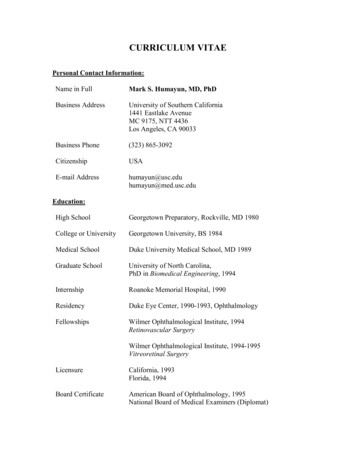
Page 5 of 14 200Nano-Micro Lett. (2021) 13:200(a)ContactWaterCut(b) Upper SurfaceHealedCross Section100 µm100 µm(c)DryContactWater OHH 2OCNFPVAHydrogen bondFig. 1 a Photographs of damaged CNF/PVA film (left) and self-healed CNF/PVA film (right). b SEM images of upper surface (left) and crosssection (right) of self-healed position on CNF/PVA film. c Schematic illustration of the moisture-inspired self-healing mechanism of CNF/PVAfilm3.2 Conductivity and Self‑Healing Propertiesof the ElectrodesAn electrode, as an integral part of electronic devices, requiresa good electrical conductivity. In regard to e-skins, the selfhealing ability of electrodes directly determines the self-healing performance of the whole e-skin. Hence, higher requirements occur for electrodes. Here, CB and G were adopted asconductive materials, and CNF/PVA was applied as the binderto prepare screen-printable conductive ink. The electricalproperties of the electrodes can be improved through the synergistic effect of hybrid conductive fillers since conductive fillers in different dimensions can increase the contact degree andinteraction area between their interfaces [26, 27]. The detailedfabrication process is described in the Experimental Section.SEM images of the electrodes fabricated via the screen-printing technique on the CNF/PVA substrate are shown in Fig.S4. The region coated by the electrodes can be clearly distinguished from the blank substrate. As shown in the top view ofthe SEM image, the region coated by the electrodes (left side)is much rougher, and the smooth region (right side) indicatesthe surface of the CNF/PVA substrate. The SEM image of thecross section shows a uniform conductive layer fabricated viathe screen-printing technique, which is much thicker than thesubstrate. The conductivity and self-healing performance ofthe electrodes were systematically investigated. The resistivity of the electrodes reached approximately 0.045 Ω cm. Asshown in Fig. 2a, during the bending process, the strain valuecan be expressed as follows:C 2R sin(L 2R)(1)Strain h 2R(2)where C and L denote the chord and arc lengths, respectively, of the device. The curvature radius (R) can be calculated with Eq. (1). Hence, the strain value of the device canbe calculated with Eq. (2), where h is the thickness of thedevice. As shown in Fig. 2b, c, the resistance of pristine and13
Page 6 of 14Nano-Micro Lett. (2021) 13:200self-healed electrodes was measured under various bendingstrains to investigate the self-healing performance and straininterference of the electrodes. The resistance of the pristineand self-healed electrodes remained almost unchanged evenwhen the devices were bent to achieve an extremely largecurvature. The maximum resistance drift of the pristine andself-healed electrodes was 5.0% and 4.3%, respectively,under a strain of 0.48%, which indicates that the electrodesare insensitive to strain.In addition, the resistance of the electrodes increasedafter self-healing. The resistance of the electrodes wasmuch lower than that of the other functional units in e-skins.Therefore, the slight resistance drift of the electrodes causedby the self-healing process did not affect the e-skin performance. To demonstrate the necessity of the self-healing ability of electrodes, the mechanical stability of self-healableelectrodes and electrodes without a self-healing ability wasinvestigated. Electrodes fabricated with CB/G-CNF/PVAink, CB/G-PVA ink and commercial silver ink were cast ontoCNF/PVA substrates via the screen-printing technique in thefollowing measurements. Among these electrodes, the latter(b) /G-PVAelectrode0.60.40.20.0Central angleAgelectrodeStrain 0.48%HealedChord length0.8Strain 0%PristinehArc ingoutwardBendingoutwardBreak0.1(e)0.20.3Strain lectrodeCrosssectionStrain sensing areaResistance (kΩ)(a)two electrodes are without self-healing ability. These threeelectrodes on substrates were cut into two pieces. Then, theelectrodes were healed with substrates by spraying water. Asshown in Fig. 2d, the three healed electrodes were insertedinto a circuit containing a light-emitting diode (LED), andthe conductivity of the electrodes was assessed based on theLED brightness. The schematic diagram of the equivalentcircuit is shown in Fig. S5. (1) When the electrodes wereunbent, the three LEDs were activated, and the conductivityof the three electrodes was restored. In this case, the damaged parts of the electrodes were re-contacted by the selfhealing ability of the substrates regardless of whether theelectrodes had completely healed, so the electrodes remainedconductive. (2) When the electrodes were bent inwards, theconductivity of the three electrodes was unaffected, and thedamaged parts of the conductive layers were compressedinwards. Hence, the electrodes still maintained a good conductivity. (3) When the electrodes were bent outwards, onlythe LED connected to the CB/G-CNF/PVA self-healingelectrodes remained activated, while the LEDs connected tothe electrodes without a self-healing ability were deactivated50 μm50 μm50 μm50 μm50 μm50 μmUppersurface200Fig. 2 a Schematic illustration of calculation model of strain. b Resistance of pristine and self-healed electrodes under various strains and cunder strain of 0% and 0.48% measured by a digital multimeter. d Visual controlling by using CB/G-CNF/PVA electrodes, CB/G-PVA electrodes and commercial silver electrodes. The different brightnesses of LEDs indicate bending states. e SEM images of self-healed position ofCB/G-CNF/PVA electrodes, CB/G-PVA electrodes and silver electrodes. The authorshttps://doi.org/10.1007/s40820-021-00701-8
Nano-Micro Lett. (2021) 13:200and the circuits were opened, which indicates that the electrodes broke again at the damaged location during outwardbending. SEM images of the three types of healed conductive layers are shown in Fig. 2e. Based on the images of thecross section, it is observed that the substrates had all completely healed. The healing region of the electrodes was alsoobserved in top and cross-sectional views. A healing tracewas noted for the CB/G-CNF/PVA electrodes, but there wasno crack in the healed region. Through comparison, obviouscracks appeared in the healed region of the CB/G-PVA andsilver electrodes.3.3 Strain Sensing Performance and Self‑HealingProperties of the Strain SensorThe strain sensor is a vital part of e-skins, which can respondto micro-deformation and can be applied in bending or weakvibration signal monitoring. Self-healable strain sensorsbased on the CNF/PVA substrate and G-CNF/PVA conductive ink were fabricated to investigate the sensing performance and self-healing properties of the strain sensing unitof e-skins. A photograph of the obtained strain sensor isshown in the inset of Fig. 3a. Strain sensors with different Gconcentrations (50%, 60%, 70% and 80%) were fabricatedand denoted as S-50/60/70/80 to explore the influence of theG concentration on the strain sensing properties. In theory,strain sensors based on carbon nanomaterial-filled hydrogels can exhibit the maximum sensitivity at the percolationthreshold concentration [28, 29]. However, in this work,to maintain the resistance of the strain sensors within anappropriate range, G concentrations from 50 to 80% wereselected during fabrication. In regard to the strain sensorsfabricated with the different inks, response versus straincurves of the four kinds of sensors are shown in Fig. 3a.The response is defined as ΔR/R0 (%) (R–R0)/R0*100%,where R0 is the resistance of the sensor in the initial stateand R is the resistance in the bending state at the variouscurvatures. All the curves demonstrate that the response ofthe sensors increased with increasing strain. To evaluate thesensitivity of the strain sensors, the gauge factor (GF) wascalculated, which is defined as GF ΔR/(R0Δε), where ΔRand Δε denote the change in the resistance and strain, respectively. The sensitivity of the sensors decreased with increasing G concentration. Among the sensors, the S-50 sensorsattained the highest GF within the whole strain range, the GFPage 7 of 14 200in the 0.31% 0.48% strain range was 321.7, and the GF was67.1 under a strain lower than 0.31%. When the G concentration was below 50%, the resistance of the strain sensorsrapidly increased to an extremely high level with decreasingG concentration, which is unfavourable for measurementsand leads to a high consumption in applications. Hence, theS-50 sensors were chosen as the optimal device in the following measurements.I–V curves of the S-50 sensors under strains ranging from0% to 0.39% were measured, as shown in Fig. 3b (voltage:‒5 5 V). It can be observed that the I–V curves under thedifferent strains exhibit a good linearity and ohmic behaviour. The slope of the I–V curves decreased with increasing strain, suggesting an increase in resistance. Dynamicresponse curves of the S-50 sensor under the various appliedstrains were measured, as shown in Figs. 3c and S6. Thesensor exhibited an obvious response under the differentstrains. The response value increases with increasing strain,which is in accordance with the result shown in Fig. 3b.As shown in Fig. S6, the dynamic response and recoverycurves of the S-50 sensor reached nearly the same responsevalue in five measurement cycles under each applied strain,indicating a good repeatability of the sensor. The dynamicresponse curve under a stair-like strain change is shown inFig. 3d. The response curve exhibits a stair-like rise and fallwith the strain. In the bending and recovery process, theresponse values under the same strain are coincident, whichdemonstrates the excellent response and recovery propertiesof the S-50 sensors. The response and recovery speed is oneof the most important parameters for strain units of e-skinsapplied in human health monitoring because the frequencyof certain physiological signals, such as pulse, heartbeat andrespiration, ranges from 0.2 to 2.0 Hz. Figure 3e shows a single response and recovery process of the S-50 sensor undera strain of 0.22%, and the response and recovery times areapproximately 100 and 80 ms, respectively. Moreover, theeffect of the strain rate on the sensing performance of theS-50 sensors was assessed, as shown in Fig. 3f. The responsevalue of the S-50 sensors to a strain of 0.19% at the differentstrain rates remained almost invariant, so the sensor responsewas unaffected by the strain rate at frequencies ranging from0.25 to 2.00 Hz. As shown in Fig. S7, the S-50 sensors canrespond to an extremely low strain, and the resistance of thesensors exhibits an obvious change when a strain of 0.03%is applied. The mechanical durability is another crucialperformance factor of strain sensors, especially in practical13
Page 8 of 14Nano-Micro Lett. (2021) 13:200GF 67.1440.10.2 0.3Strain (%)0.4(d) 60(e) 141210864200.48%400.45%ΔR/R0 (%)ΔR/R0 9%0.15%0.10%201000(g) 20204060 80 100 120 140Time (s)%%0.450.42%%0.390.36%%0.310.2800515(f) 18Strain 0.22%0.25 Hz153045Time (s)0.5 Hz60751 Hz 2 Hz12100 ms 0.280 ms0.00.2 0.4 0.6Time (s)96300.81.00510 15 20 25 30 35 40Time (s)(h)815ΔR/R0 (%) 45 5 4 3 2 1 0 1 2 3 4Voltage (V)0.520ΔR/R0 (%)0.03010 30GF 75.7040% 15Recovery2050%GF 126.20600.19GF 197.915(c)0.1%0.19%0.25%0.31%0.36%0.1%30GF 321.7400%0.15%0.22%0.28%0.33%0.39%ResponseΔR/R0 (%)60(b) 45S-60S-80ΔR/R0 (%)S-50S-70Current (nA)(a) 800.22200401055057560045504575460050 58 100 15401000 2000 3000 4000 5000Time (s)Fig. 3 a Response vs strain curves of S-50/60/70/80 sensors. b I–V curves of the S-50 sensors under strains from 0 to 0.39%. c Dynamicresponse curves of S-50 sensor under various applied strains. d Dynamic response curve under a stair-like strain change. e Fast response andrecovery speed of S-50 sensor. f Relative resistance variations under cyclic loading–unloading with a strain of 0.19% at the frequency of 0.25 to2 Hz. g Current–time curves of the S-50 sensor for 5000 loading/unloading cycles with an applied strain of 0.25%. h Schematic diagram of thestrain sensing mechanismapplications. As shown in Fig. 3g, the durability of the S-50sensors was tested by repeatedly loading–unloading a strainof 0.25% over 5000 cycles, and the sensor maintained itssensing performance throughout 5000 cycles of the loading–unloading process. Based on the enlarged curves ininsets, there is no notable difference between the anterior50 s and posterior 50 s periods of the whole measurementcurve, indicating the outstanding durability and reliability ofthe S-50 sensors. Considering the stretching or compressingcaused by strain may occur at local stress concentration positions in strain sensors, which can affect the sensor thicknessand cause system errors. The thickness distribution of the The authorsCNF/PVA film under bending was also evaluated (Fig. S8).The system error caused by the thickness variation duringthe strain-sensitive unit performance measurement is calculated far less than 1.39% (Details are discussed in Fig. S8).A schematic diagram of the strain sensing mechanismis shown in Fig. 3h. When a bending strain is applied tothe sensor, relative sliding may occur between the graphite sheets of the sensitive layer. If the strain reaches a high
onto a self-healing polymer substrate via magnetron sputter - ing, evaporation, spray or drop casting [1720-]. Typically, the functional layer does not exhibit a self-healing ability, but the self-healing process of the substrate re-establishes contact between damaged functional layers to restore device function.