Transcription
Pub. 42004-470GGAI-TRONICS A HUBBELL COMPANYClean Phone VoIP TelephonesTABLEOFCONTENTSConfidentiality Notice .1Product Overview .1Models . 2System Requirements and Limitations . 2Tips for VoIP Subscribers . 2Features and Functions . 3Operation .3Placing an Autodial Call . 3Placing a General Telephone Call . 3Receiving a Call . 3Multicast Broadcasting . 4Monitoring and Reporting . 4Installation .4General Information . 4Safety Guidelines. 5Station Placement. 5Model 295-702F . 5Model 295-702W . 8Field Wiring. 9Power . 10Network. 10I/O . 10Recommended Cabling . 11Status Indication . 11Power . 11Heartbeat . 11EACT . 11Programming .11VoIP PCBA Setup . 12VoIP PCBA Initial Network Configuration . 12VoIP Telephone Input Contacts . 12VoIP Telephone Output Contacts . 12GAI-TRONICS 3030 KUTZTOWN RD. READING, PA 19605 USA610-777-1374 800-492-1212 Fax: 610-796-5954VISIT WWW.GAI-TRONICS.COM FOR PRODUCT LITERATURE AND MANUALS
Table of ContentsPub. 42004-470GMaintenance .13General Information . 13Service . 13Troubleshooting . 13Replacement Parts and Accessories . 14Specifications .14Power. 14Networking . 14Inputs . 14Outputs . 14Indicators . 14Mechanical . 14Model 295-702F Clean Phone . 15Model 295-702W Clean Phone . 15Chemical Resistance . 15Approvals .15GAI-TRONICS 3030 KUTZTOWN RD. READING, PA 19605 USA610-777-1374 800-492-1212 Fax: 610-796-5954VISIT WWW.GAI-TRONICS.COM FOR PRODUCT LITERATURE AND MANUALS
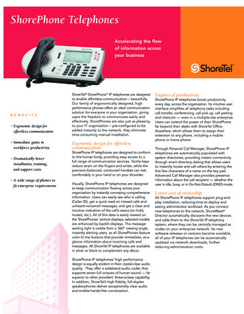
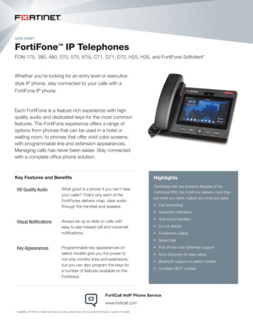
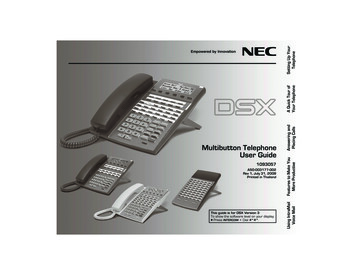
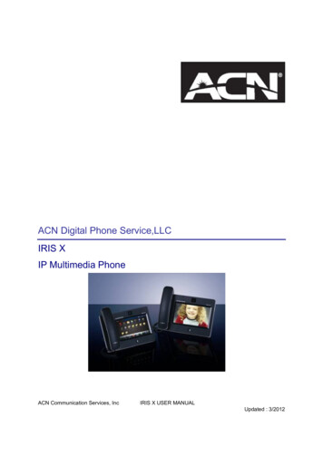
Pub. 42004-470GGAI-TRONICS A HUBBELL COMPANYClean Phone VoIP TelephonesConfidentiality NoticeThis manual is provided solely as an installation, operation, and maintenance guide and contains sensitivebusiness and technical information that is confidential and proprietary to GAI-Tronics. GAI-Tronicsretains all intellectual property and other rights in or to the information contained herein, and suchinformation may only be used in connection with the operation of your GAI-Tronics product or system.This manual may not be disclosed in any form, in whole or in part, directly or indirectly, to any thirdparty.Product OverviewThe GAI-Tronics Model 295-702F Flush-Mount and Model 295-702W Wall-Mount Clean Phone VoIP(Voice over Internet Protocol) Telephones are designed for the exacting requirements of clean rooms.They are constructed of stainless steel and have a completely smooth polyester front panel that will nottrap particulate matter. Calls are made by pressing one of the three auto-dial buttons or by using the fullyfunctional keypad. The oversized, clearly labeled buttons allow for easy operation with gloved hands.The Clean Phone VoIP telephones are designed for connection to a 10/100 BaseT Ethernet network. Thetelephones operate from PoE (Power-over-Ethernet) or an external power source. The VoIP telephonesprovide direct point-to-point communication between personnel throughout the facility over an existingLAN.Figure 1. Model 295-702FFigure 2. Model 295-702WGAI-TRONICS 3030 KUTZTOWN RD. READING, PA 19605 USA610-777-1374 800-492-1212 Fax: 610-796-5954VISIT WWW.GAI-TRONICS.COM FOR PRODUCT LITERATURE AND MANUALS
Pub. 42004-470GPage 2 of 15Clean Phone VoIP TelephonesModelsThe following Clean Phone VoIP telephones are detailed in this manual:Table 1. Model ChartModelDescription295-702WSurface-Mount VoIP Telephone with stainless steel front panel and polyester overlay,three autodial buttons, hookswitch push button, off-hook indicator, keypad, andstainless-steel surface-mount enclosure.295-702FFlush-Mount VoIP Telephone with stainless steel front panel and polyester overlay,three autodial buttons, hookswitch push button, off-hook indicator, keypad, andstainless-steel mounting bracket.System Requirements and LimitationsVoIP telephones require PoE (Power-over-Ethernet) or a local 24–48 V dc power source for operation.Two VoIP telephones can be connected in a peer-to-peer configuration without the need for a LAN.However, a 10/100 BaseT Ethernet network with SIP (Session Initiation Protocol) server is required forsystems containing three or more VoIP telephones. Conferences are limited by the customer’s LANmedia capabilities and the services available at each telephone.Each telephone can also receive multicast broadcasts. Multicast allows a single audio stream to be sent tomultiple end points simultaneously, achieving multi-point paging, or public address functionality over IP.Multicast requires the use of a SIP server that specifically supports multicast functionality and eachtelephone must be configured (enabled) to receive multicast packets.Tips for VoIP SubscribersRecommended actions for VoIP subscribers: Provide an accurate physical address to the interconnected VoIP service provider for dispatch ofemergency services to the location. Know the VoIP service provider’s procedures for updating the address. Promptly update addressinformation in the event of a change. Have a clear understanding of all limitations of the 911 service. VoIP service may not work when the power is out, or the Internet connection is down. Considerinstalling a backup power supply, maintaining a traditional telephone line, or having a wirelesstelephone as a backup. See http://www.fcc.gov/cgb/consumerfacts/voip.html for questions about interconnected VoIP and911 or about VoIP in general.P:\Standard IOMs - Current Release\42004 Instr. Manuals\42004-470G.docx05/19
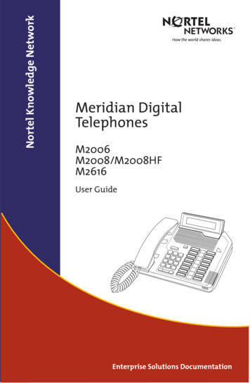
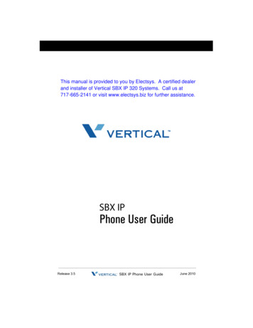
Pub. 42004-470GPage 3 of 15Clean Phone VoIP TelephonesFeatures and FunctionsThe Clean Phone VoIP telephones include the following features: SIP compatible (RFC3261) automatic call diversion (memory list) real-time alarm reporting via email, syslog, or TMA software configurable via web page, serial link, or download four auxiliary inputs two voltage-free contact outputs multicast capability, up to eight addressesOperationPlacing an Autodial CallTo place an autodial call:Press the desired autodial push button to place animmediate call to a preprogrammed number.The hookswitch indicator illuminates whenthe call is connected.The call is terminated by: pressing the ON/OFF push buttonthe receiving caller hangs upthe call duration timeout is exceededSIP server disconnects the callPlacing a General TelephoneCallTo place a general telephone call:Figure 3. Front Panel1. Press the ON/OFF push button.2. Wait for the dial tone.3. Use the keypad to dial the desired number.The hookswitch indicator illuminates when the call is connected.4. The call is terminated by: pressing the ON/OFF push buttonthe receiving caller hangs upthe call duration timeout is exceededSIP server disconnects the callReceiving a CallClean Phone VoIP telephones automatically go off-hook (auto-answer) when called.P:\Standard IOMs - Current Release\42004 Instr. Manuals\42004-470G.docx05/19
Clean Phone VoIP TelephonesPub. 42004-470GPage 4 of 15Multicast BroadcastingThe SIP server sends a paging request to a specific multicast IP address and expects multiple telephonesto accept and play the subsequent audio when making a multicast call. GAI-Tronics VoIP telephones canbe programmed for up to eight multicast addresses to permit the receipt of multicast broadcasts fromdifferent sources or to enable zoning of broadcasts. Each multicast address can be assigned a priority (viaprogramming) to define audio source priority. A telephone with multicast enabled can still make andreceive normal calls (peer-to-peer or SIP server). Normal calls can be assigned a priority level, definingwhether calls can override multicasts or vice versa.Monitoring and ReportingEach telephone can recognize and generate several hardware and configuration fault condition alarms.These alarms can be signaled to a remote site using three methods: syslog output over TCP SMTP mail message TMA (Telephone Management Application) software (purchased separately)Available alarms: handset integrity loop (if applicable) configuration error cold reset (power cycle) warm reset (internal command) keypad error (if applicable) key-hook (off hook status, if applicable) register fail audio path test (speaker/microphone test)InstallationGeneral InformationWARNING—This product can contain hazardous voltages. Always remove power to thisstation and any associated equipment before beginning any installation.CAUTION—Do not install this equipment in areas other than those indicated on the approvalstandards listing in the Approvals section of this manual. Such installation maycause a safety hazard and consequent injury or property damage.Install equipment without modification and according to all applicable local and national electrical codes.Consult the National Electrical Code (NFPA 70), Canadian Standards Association (CSA 22.1), and localcodes for specific requirements regarding your installation. Class 2 circuit wiring must be performed inaccordance with NEC 725.55.P:\Standard IOMs - Current Release\42004 Instr. Manuals\42004-470G.docx05/19
Pub. 42004-470GPage 5 of 15Clean Phone VoIP TelephonesSafety GuidelinesAdhere to the following guidelines to ensure the safety of all personnel when installing any GAI-Tronicsequipment: Do not install wiring during a lightning storm. Electrostatic Discharge (ESD) Protection: The VoIP telephone may have an earth ground terminalprovision. If so, it must be connected to ground in accordance with all local safety regulations andthe National Electrical Code (NEC). Grounding must be ensured for safe and stable communications.Do not use long and coiled ground wires. Trim ground wires to the required length. Use a starconfiguration whenever possible. Please note that proper grounding does not eliminate the need forlightning protection for the telephone or the telephone system. A Cat5 data line lightning surgeprotector is recommended for telephones subject to any electrostatic discharge (e.g. lightning). Do not install jacks in wet locations unless the jack is specifically designed for wet locations.Station PlacementVolume settings and station placement must be taken into consideration to prevent feedback problems inthe system. To reduce unpleasant feedback problems: point the telephone away from other telephones located nearby reduce the volume levelAvoid feedback problems by installing each Clean Phone VoIP telephone in a separate room and wall.Model 295-702FThe mounting and wiring instructions are as follows:1. Remove the front panel from the back bracket.2. Mark the wall using the cut-out dimensions as a guide (see Figure 6).3. Make the required cuts to create the opening for the back box.4. If using Power-over-Ethernet, with no optional inputs or outputs:place the bushing around the Ethernet cable so that it is locatedapproximately 5 inches from the end of the cable. Snap thebushing closed and insert into the double D hole in the bottom ofthe back bracket. See Figure 4 and Figure 7).5. If using local power or optional inputs or outputs: route thecables through the D hole in the bottom of the back bracket (seeFigure 7).6. Place the back bracket in the wall. Locate the mounting holes(see Figure 7).Figure 4. Bushing7. Drill holes in the lower right and upper left corners and secure thebracket with screws.8. Drill the remaining holes and secure the bracket with the remaining screws.9. Plug in the Ethernet cable and connect all other optional cables (see the Field Wiring section).10. Perform the initial programming of the telephone (see the Programming section).11. Take the front panel of the VoIP Clean Phone and align it with four slots in the back bracket.12. Press the panel in firmly and then push downward to seat the panel in the slots.P:\Standard IOMs - Current Release\42004 Instr. Manuals\42004-470G.docx05/19
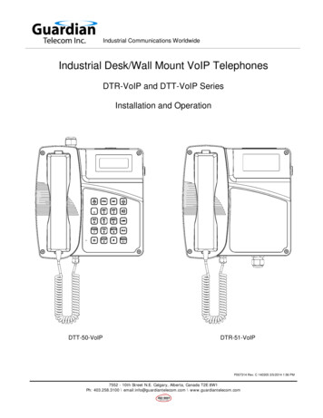
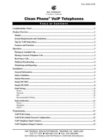
Pub. 42004-470GPage 6 of 15Clean Phone VoIP TelephonesNOTE: The Model 295-702F is designed for general wipe down cleaning and to prevent collection(internally and externally) of particulate matter. Additional protection against moisture can beattained by sealing between the outer edge of the telephone panel to the mounting surface withsilicone or RTV. Any sealing substance used must be verified to be compatible with cleaningsolutions used.Figure 5. Inside Front PanelP:\Standard IOMs - Current Release\42004 Instr. Manuals\42004-470G.docx05/19
Pub. 42004-470GPage 7 of 15Clean Phone VoIP TelephonesFigure 6. Wall Cut-out Dimensions for Model 295-702FFigure 7. Back Box for Model 295-702FP:\Standard IOMs - Current Release\42004 Instr. Manuals\42004-470G.docx05/19
Clean Phone VoIP TelephonesPub. 42004-470GPage 8 of 15Model 295-702WThe mounting and wiring instructions are as follows:1. Remove the front panel from the back box.2. If using Power-over-Ethernet, with no optional inputs or outputs: place the bushing around theEthernet cable so that it is located approximately 5 inches from the end of the cable. Snap thebushing closed and insert it into the double D hole in the back box (see Figure 4 and Figure 8).3. If using local power or optional inputs or outputs: route the cables through the D hole in the bottomof the back box (see Figure 4 and Figure 8).4. Position the back-box so that it is level on the wall in the desired location.5. Use the back box as a template to drill the lower right and upper left corners holes and secure theback box with screws.6. Drill the remaining holes and completely secure the box with the remaining screws.7. Plug in the Ethernet cable and connect all other optional cables (see the Field Wiring section).8. Perform the initial programming of the telephone (see the Programming section).9. Align the front panel of the Clean Phone with the four slots in the back box.10. Press the panel in firmly and push it downward to seat it in the slots.NOTE: The Model 295-702W VoIP Telephone is designed for general wipe down cleaning and to preventcollection (internally and externally) of particulate matter.Figure 8. Mounting the Model 295-702WP:\Standard IOMs - Current Rele
Flush-Mount VoIP Telephone with stainless steel front panel and polyester overlay, three autodial buttons, hookswitch push button, off-hook indicator, keypad, and stainless-steel mounting bracket. System Requirements and Limitations VoIP telephones require PoE (Power-over-Et