Transcription
BOOK greenIEEE142 IEEE Recommended Practice forGrounding ofIndustrial andCommercial PowerSystemsPublished by theInstitute of Electrical andElectronics Engineers, Inc.IEEE Std 142 -2007(Revision ofIEEE Std 142-1991)
IEEE Std 142 -2007(Revision ofIEEE Std 142-1991)IEEE Recommended Practicefor Grounding of Industrial andCommercial Power SystemsSponsorPower Systems Engineering Committeeof theIEEE Industry Applications SocietyApproved 7 June 2007IEEE-SA Standards Board
ContentsChapter 1System grounding . 11.1 Introduction.11.2 Definitions.21.3 Purposes of system grounding .41.4 Methods of system neutral grounding.51.5 Obtaining the system neutral .221.6 Location of system grounding points.281.7 Grounding of industrial and commercial generators .381.8 Autotransformers .481.9 System grounding for uninterruptible power systems .531.10 Portable mining equipment supply systems.571.11 Creation of stray currents and potentials .601.12 Avoiding common-mode noise.621.13 Limiting transferred earth potentials.631.14 “Resonantly” produced voltages.641.15 Grounding of dc power systems .661.16 Normative references .701.17 Bibliography .73Chapter 2Equipment grounding. 752.1 Basic objectives .752.2 Fundamental concepts.772.3 Equipment grounding as influenced by type of use.952.4 Outdoor open-frame substations .952.5 Unit substations.992.6 Installations serving heavy portable electric machinery.1002.7 Interior wiring systems .1042.8 Interior unit substations and switching centers.1102.9 Utilization equipment.1112.10 Normative references .1142.11 Bibliography .116Chapter 3Static and lightning protection grounding. 1193.1 Introduction.1193.2 Static grounding .1193.3 Lightning protection grounding .1403.4 Normative references .1563.5 Bibliography .159Copyright 2007 IEEE. All rights reserved.vii
Chapter 4Connection to earth . 1614.1 Resistance to earth .1614.2 Ground electrodes .1694.3 Methods and techniques of construction.1744.4 Measurement of resistance to earth.1764.5 Normative references .182Chapter 5Electronic equipment grounding. 1875.1 Introduction.1875.2 Definitions.1875.3 History of computer grounding.1885.4 System or equipment to be grounded.1905.5 Grounding electronic equipment.1915.6 Effects of internal rectifiers in computers.2005.7 Grounding of shields.2015.8 Interference from radio frequencies.2045.9 Case histories .2055.10 Normative references .2075.11 Bibliography .208Index . 211viiiCopyright 2007 IEEE. All rights reserved.
IEEE Recommended Practicefor Grounding of Industrial andCommercial Power SystemsChapter 1System grounding1.1 Introduction1.1.1 OverviewThis chapter provides recommended procedures for the system grounding of industrialand commercial power systems, and the proper selection and application of groundingimpedances. Special cases of system grounding are also addressed for generators,uninterruptible power supplies (UPS), portable mining equipment, and multi-voltagesystems.1.1.2 GeneralGrounding of an electrical system is a decision that must be faced sometime by mostengineers charged with planning or modifying electrical distribution. Grounding in someform is generally recommended, although there are certain exceptions. Several methodsand criteria exist for system grounding; each has its own purpose.It is the intention of this chapter to assist the engineer in making decisions on the subjectby presenting basic reasons for grounding or not grounding and by reviewing generalpractices and methods of system grounding.The practices set forth herein are primarily applicable to industrial power systems thatdistribute and utilize power at medium or low voltage, usually within a smallergeographical area than is covered by a utility.Where distances or power levels may dictate circuitry and equipment similar to a utility,consideration of utility practices is warranted. However, restrictions of the NationalElectrical Code (NEC ), NFPA 701 particular needs of service and the experience andtraining of the workforce should also be considered.1Informationon references can be found in 1.16.Copyright 2007 IEEE. All rights reserved.1
IEEEStd 142-2007CHAPTER 1Where an industrial power system includes power-generating equipment, the reasons forgrounding these components may be the same as those for grounding similar componentsof public utility systems. The methods of grounding would generally be similar under likeconditions of service. However, in the industrial setting, conditions of service may bealtered by the following:a)Location within the power systemb)Individual generator characteristicsc)Manufacturing process requirementsAll of these may affect grounding decisions.The NEC, sponsored by the National Fire Protection Association, contains regulationspertaining to system and equipment grounding applicable to industrial, commercial, andspecial occupancy facilities. These rules are considered minimum requirements for theprotection of life and property and should be carefully reviewed during the course ofsystem design. The recommended practices in this document are intended to supplement,and not negate, any of the requirements in the NEC.1.2 DefinitionsFor the purposes of this document, the following terms and definitions apply. TheAuthoritative Dictionary of IEEE Standards Terms [B8]2 and the NEC should bereferenced for terms not defined in this subclause.1.2.1 effectively grounded: Grounded through a sufficiently low impedance such that forall system conditions the ratio of zero-sequence reactance to positive-sequence reactance(X0/X1) is positive and not greater than 3, and the ratio of zero-sequence resistance topositive-sequence reactance (R0/X1) is positive and not greater than 1.1.2.2 equipment grounding conductor (EGC): The conductor used to connect the noncurrent-carrying metal parts of the equipment, raceways, and other enclosures to thesystem grounded conductor, the grounding electrode conductor (GEC), or both, at theservice equipment or at the source of a separately derived system.1.2.3 ground: A conducting connection, whether intentional or accidental, between anelectrical circuit or equipment and the earth, or to some other body that serves in place ofthe earth.1.2.4 grounded: Connected to earth or to an extended conducting body that serves insteadof the earth, whether the connection is intentional or accidental.1.2.5 grounded system: A system in which at least one conductor or point (usually themiddle wire or neutral point of transformer or generator windings) is intentionallygrounded, either solidly or through an impedance.2The2numbers in brackets correspond to those of the bibliography in 1.17.Copyright 2007 IEEE. All rights reserved.
SYSTEM GROUNDINGIEEEStd 142-20071.2.6 grounding system: A system that consists of all interconnected groundingconnections in a specific power system and is defined by its isolation from adjacentgrounding systems. The isolation is provided by transformer primary and secondarywindings that are coupled only by magnetic means. Thus, the system boundary is definedby the lack of a physical connection that is either metallic or through a significantly highimpedance.1.2.7 high-resistance grounded: A resistance-grounded system designed to limit groundfault current to a value that can be allowed to flow for an extended period of time, whilestill meeting the criteria of R0 Xco, so that transient voltages from arcing ground faultsare reduced. The ground-fault current is usually limited to less than 10 A, resulting inlimited damage even during prolonged faults.1.2.8 low-resistance grounded: A resistance-grounded system that permits a higherground-fault current to flow to obtain sufficient current for selective relay operation.Usually meets the criteria of R0/X0 less than or equal to 2. Ground-fault current is typicallybetween 100 A and 1000 A.1.2.9 per-phase charging current (Ico): The current (Vln/Xco) that passes through onephase of the system to charge the distributed capacitance per phase-to-ground of thesystem; Vln is the line-to-neutral voltage and Xco is the per-phase distributed capacitivereactance of the system.1.2.10 reactance grounded: Grounded through an impedance, the principal element ofwhich is inductive reactance.1.2.11 resistance grounded: Grounded through an impedance, the principal element ofwhich is resistance.1.2.12 resonant grounded: A system in which the capacitive charging current isneutralized by an inductive current produced from a reactor connected between the systemneutral and ground. By properly “tuning” the reactor (selecting the right tap), a lowmagnitude of fault current can be achieved. In general, when this occurs the arc will notmaintain itself and the ground fault is extinguished or “quenched.” In a parallel circuit,consisting of L and C, this happens when,11ωL -------- or f ------------------ωC2π LC1.2.13 Rn: The value of the resistance connected from the neutral to the ground of aresistance-grounded system. For high-resistance grounded systems where Rn is a majorcomponent of R0, the relationship R0 3Rn applies.1.2.14 R0: The per-phase zero-sequence resistance of the system.1.2.15 separately derived system: A wiring system whose power is derived from agenerator, transformer, or converter windings and has no direct electrical connection,Copyright 2007 IEEE. All rights reserved.3
IEEEStd 142-2007CHAPTER 1including a solidly connected grounded circuit conductor, to supply conductorsoriginating in another system.1.2.16 solidly grounded: Connected directly through an adequate ground connection inwhich no impedance has been intentionally inserted.1.2.17 static charge: The electricity generated when two dissimilar substances come intocontact. Conveyor belts are active producers of static electricity.1.2.18 switching surge: A transient wave of overvoltage in an electric circuit caused bythe operation of a switching device interrupting current.1.2.19 system charging current: The total distributed capacitive charging current (3Vln/Xco) of a three-phase system.1.2.20 three-phase, four-wire system: A system of alternating current supply comprisingfour conductors, three of which are connected as in a three-phase three-wire system, thefourth being connected to the neutral point of the supply or midpoint of one phase in caseof delta-connected transformer secondary for the purpose of conducting load current.1.2.21 three-phase, three-wire system: A system of alternating current supplycomprising three conductors, between successive pairs of which are maintainedalternating differences of potential successively displaced in phase by one third of aperiod.1.2.22 transient overvoltage: The temporary overvoltage associated with the operation ofa switching device, a fault, a lightning stroke, an arcing ground fault on an ungroundedsystem, or other instigating events.1.2.23 ungrounded system: A system without an intentional connection to ground exceptthrough potential indicating or measuring devices or other very high-impedance devices.1.2.24 Xco: The distributed per-phase capacitive reactance to ground of the system.1.2.25 X0: Zero-sequence reactance of the system.1.2.26 X1: Positive-sequence reactance of the system.1.2.27 X2: Negative-sequence reactance of the system.1.3 Purposes of system groundingSystem grounding is the intentional connection to ground of a phase or neutral conductorfor the purpose of:a)4Controlling the voltage with respect to earth, or ground, within predictable limits,andCopyright 2007 IEEE. All rights reserved.
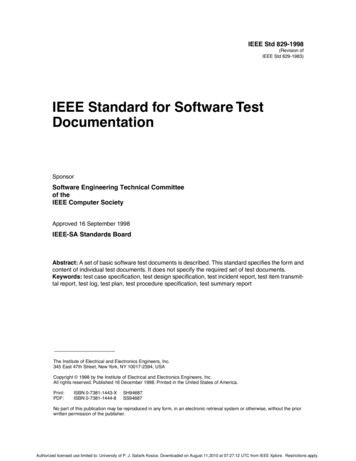
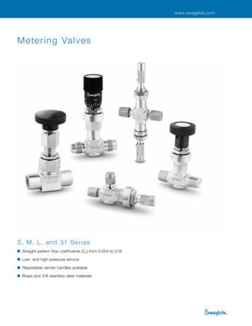
SYSTEM GROUNDINGb)IEEEStd 142-2007Providing for a flow of current that will allow detection of an unwantedconnection between system conductors and ground. Such detection may theninitiate operation of automatic devices to remove the source of voltage from theseconductors.The NEC prescribes certain system grounding connections that must be made to be incompliance with the code. The control of voltage to ground limits the voltage stress on theinsulation of conductors so that insulation performance can more readily be predicted. Thecontrol of voltage also allows reduction of shock hazard to persons who might come incontact with live conductors.1.4 Methods of system neutral grounding1.4.1 IntroductionMost grounded systems employ some method of grounding the system neutral at one ormore points. These methods can be divided into two general categories: solid groundingand impedance grounding. Impedance grounding may be further divided into severalsubcategories: reactance grounding, resistance grounding, and ground-fault neutralizergrounding. Figure 1-1 shows examples of these methods of grounding.Each method, as named, refers to the nature of the external circuit from system neutral toground rather than to the degree of grounding. In each case the impedance of the generatoror transformer whose neutral is grounded is in series with the external circuit. Thus asolidly grounded generator or transformer may or may not furnish effective grounding tothe system, depending on the system source impedance.Many of the concepts involved in defining system grounding types and levels are bestexplained in terms of symmetrical components or equivalent circuits. The reader who isnot familiar with these analytical methods is referred to Chapter 2 of Beeman and toChapter 3 of IEEE Std 399 (IEEE Brown Book ) for guidance.Molded-case circuit-breaker interrupting capabilities can be affected by the method ofgrounding. In addition, if other than solidly grounded wye systems are used, the circuitbreakers’ single-pole interrupting ratings should be evaluated for the application1.4.2 Ungrounded system (no intentional grounding)In an ungrounded system, there is no intentional connection between the systemconductors and ground. However, as shown in Figure 1-2, there always exists a capacitivecoupling between one system conductor and another, and also between system conductorsand ground. Consequently, the so-called ungrounded system is in reality a capacitancegrounded system, by virtue of the distributed capacitance from the system conductors toground. Since the capacitance between phases has little effect on the groundingcharacteristics of the system, it will be disregarded. For simplicity, the distributedcapacitive reactance to ground, Xco, is assumed to be balanced.Copyright 2007 IEEE. All rights reserved.5
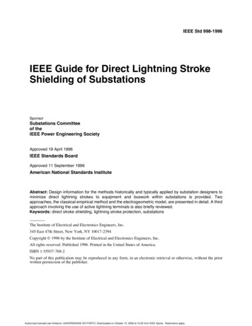
IEEEStd 142-2007CHAPTER 1Figure 1-1—System neutral circuit and equivalent diagrams forungrounded and grounded systemsIn an unfaulted condition, with balanced three-phase voltages applied to the lines, thecapacitive charging current, Ico, in phase will be equal and displaced 120 from oneanother. The phase voltages to ground will also be equal and displaced 120 from oneanother. The vectors relationships are shown in part b) of Figure 1-2. Since the neutral ofthe distributed capacitances is at earth potential, it follows that the neutral of thetransformer is also at earth potential, being held there by the capacitance to ground.If one of the system conductors, phase C for example, faults to ground, current flowthrough that capacitance to ground will cease, since no potential difference across it nowexists. The voltage across the remaining two distributed capacitors to ground will,however, increase from line to neutral to line to line. The capacitive charging current, Ico,6Copyright 2007 IEEE. All rights reserved.
SYSTEM GROUNDINGIEEEStd 142-2007in the two unfaulted phases will therefore increase by the square root of 3. As shown inFigure 1-3, the line-to-ground voltages are no longer 120 , but 60 apart.Hence, the vectorial sum of the capacitive charging current to ground is no longer zero,but is 3 Ico or three times the original charging current per phase. The fault current, Ig,flowing from the faulted conductor to ground, leads the original line-to-neutral voltage(Vnc –Vcn) by approximately 90 .Figure 1-2—Ungrounded system: (a) circuit configuration,(b) vector diagramIn an ungrounded system, it is possible for destructive transient overvoltages to occurthroughout the system during restriking ground faults. These overvoltages, which can beseveral times normal in magnitude, result from a resonant condition being establishedbetween the inductive reactance of the system and the distributed capacitance to ground.This phenomenon is discussed in detail by Beeman. Experience has proved that theseCopyright 2007 IEEE. All rights reserved.7
IEEEStd 142-2007CHAPTER 1overvoltages may cause failure of insulation at multiple locations in the system,particularly at motors. Transient overvoltages from restriking ground faults are the mainreason why ungrounded systems are no longer recommended and grounded systems ofsome form are the predominant choice. To reduce transient overvoltages during restrikingground faults, one should ground the system using either solid or impedance grounding asindicated in Figure 1-4.Various detection schemes are used to detect the presence of a single line-to-ground fault.The simplest scheme employs three light bulbs, each connected between line voltage andground. Under normal operation the three bulbs are illuminated with low equal intensity.When a single line-to-ground fault occurs, that bulb connected to the faulted phase isextinguished. The remaining two bulbs increase in intensity, since the voltage on theunfaulted phases increases from line-to-neural to line-to-line.Figure 1-3—Single line-to-ground fault on an ungrounded system:(a) circuit configuration, (b) vector diagram8Copyright 2007 IEEE. All rights reserved.
SYSTEM GROUNDINGIEEEStd 142-2007Figure 1-4—Independent grounding of each voltage levelAnother scheme frequently used takes the form of three voltage transformers with theirprimary windings connected in wye and the neutral point grounded. The secondarywindings of the transformers are connected in broken delta, with a voltage relay connectedin the open corner and used to operate an indication or alarm circuit. Using this scheme,loading resistors may be required either in the primary neutral or secondary circuit toavoid ferroresonance.The problem of locating a single line-to-ground fault on an ungrounded system can betime consuming. Usually, the first step is to open the secondary feeders, one at a time, todetermine on which feeder the fault is located. Afterwards, the branch circuits are openedone at a time. Finally, the individual loads are taken off. None of these proceduresimproves service continuity.Copyright 2007 IEEE. All rights reserved.9
IEEEStd 142-2007CHAPTER 1If a ground cannot be located before a second line-to-ground fault occurs, whose currentmust be carried by the EGC or earth, the result will be a line-to-line fault. This will becontrasted later to a grounded system that develops enough ground current to clear,automatically and selectively, each faulted circuit.1.4.3 Resistance groundingIn a resistance-grounded system, the neutral of the transformer or generator is connectedto ground through a resistor. A typical resistance-grounded neutral system is shown inFigure 1-5. As commonly installed, the resistance has a considerably higher ohmicmagnitude than the system reactance at the resistor location. Consequently, the line-toground fault current is primarily limited by the resistor itself.The reasons for limiting the current by resistance grounding include the following:a)To reduce burning and melting effects in faulted electric equipment, such asswitchgear, transformers, cables, and rotating machines.b)To reduce mechanical stresses in circuits and apparatus carrying fault currents.c)To reduce electric-shock hazards to personnel caused by stray ground-faultcurrents in the ground-return path.d)To reduce the arc blast or flash hazard to personnel who may have accidentallycaused or happen to be in close proximity to the ground fault.e)To reduce the momentary line-voltage dip occasioned by the occurrence andclearing of a ground fault.f)To secure control of transient overvoltages while at the same time avoiding theshutdown of a faulted circuit on the occurrence of the first ground fault (highresistance grounding).Resistance grounding may be either of two classes, high resistance or low resistance,distinguished by the magnitude of ground-fault current permitted to flow. Although thereare no recognized standards for the levels of ground-fault current that define these twoclasses, in practice there is a clear difference.Figure 1-5—Resistance-grounded system10Copyright 2007 IEEE. All rights reserved.
SYSTEM GROUNDINGIEEEStd 142-20071.4.3.1 High-resistance groundingHigh-resistance grounding employs a neutral resistor of high ohmic value. The value ofthe resistor is selected to limit the current, Ir, to a magnitude equal to or slightly greaterthan the total capacitance charging current, 3 Ico, as shown in Figure 1-6.Typically, the ground-fault current, Ig, is limited to 10 A or less, although somespecialized systems at voltages in the 15 kV class may require higher ground-fault levels.In general, the use of high-resistance grounding on systems where the line-to-ground faultexceeds 10 A should be avoided because of the potential damage caused by an arcingcurrent larger than 10 A in a confined space (see Foster, Brown, and Pryor).Several references are available that give typical system charging currents for major itemsin the electrical system (see Electrical Transmission and Distribution Reference Book;Baker). These will allow the value of the neutral resistor to be estimated in the projectdesign stage. The actual system charging current may be measured prior to connection ofthe high-resistance grounding equipment following the manufacturer’s recommendedprocedures.Figure 1-6—Single line-to-ground fault on a high-resistance groundedsystem: (a) circuit configuration, (b) vector diagramCopyright 2007 IEEE. All rights reserved.11
IEEEStd 142-2007CHAPTER 1High-resistance grounding usually does not require immediate clearing of a ground faultsince the fault current is limited to a very low level. The protective scheme associated withhigh-resistance grounding is usually detection and alarm rather than immediate trip out.A typical scheme for detecting a ground fault in a high-resistance grounded system isshown in Figure 1-7. Under normal operation, the neutral point of the transformer is atzero potential. When a single line-to-ground fault occurs, the neutral point is raised toapproximately line-to-neutral voltage. This rise in voltage is then detected using anovervoltage relay, 59. A step-down transformer is typically used to reduce the line toneutral voltage of the system to a level (usually 120 V) acceptable to the relay. Since aground fault may persist for an indefinite length of time, a continuous (rather than shortterm) rating should be imposed on the grounding resistor.Figure 1-7—Scheme for detecting a ground fault on a high-resistancegrounded systemHigh-resistance grounding has the following advantages:a)Service continuity is maintained. The first ground fault does not require processequipment to be shut down.b)Transient overvoltage due to restriking ground faults is reduced (to 250% ofnormal).c)A signal tracing or pulse system will facilitate locating a ground fault.d)It eliminates flash hazards to personnel associated with high ground-fault currents.e)The need for and expense of coordinated ground-fault relaying is eliminated.High-resistance grounding is generally employed in the following:1)12Low voltage (where permitted), i.e., commercial and industrial locations wherethere are no line-to-neutral loads.Copyright 2007 IEEE. All rights reserved.
SYSTEM GROUNDINGIEEEStd 142-20072)Medium-voltage systems where service continuity is desired and capacitive charging current is not excessive.3)Retrofits of previously ungrounded systems where it is desired to reduce transientovervoltages potentially caused by restriking ground faults.1.4.3.2 Low-resistance groundingLow-resistance grounding is designed to limit ground-fault current to a range between100 A and 1000 A, with 400 A being typical. The neutral resistor, R, shown in Figure 1-8,is selected according to R Vln/Ig, where Vln is the system line to neutral voltage and Ig isthe desired ground-fault current. Figure 1-9 illustrates the flow of currents for a singleline-to-ground fault on a low-resistance grounded system. Since the combined effects ofcharging current and system source impedance will affect the ground-current value lessthan 0.5% in the typical range of utility supplied systems, it is permissible to ignore theseeffects in calculating the ground-fault resistance value. The general practice is to considerthat the full system line-to-neutral voltage appears across the grounding resistor. Only inthe case of systems supplied by small generators should departure from this generalpractice be considered.Figure 1-8—Low-resistance grounded systemLow-resistance grounding has the advantage of facilitating the immediate and selectiveclearing of a grounded circuit. This requires that the minimum ground-fault current belarge enough to positively actuate the applied ground-fault relay. One method of detectingthe presence of a ground fault uses an overcurrent relay, 51G. This method is presented inFigure 1-10. When a ground fault occurs, the neutral potential is raised to approximatelyline-to-neutral voltage, resulting in current flow through the resistor. A typical turns ratiofor the current transformer is indicated. Upon indication that a ground fault has occurred,action would be initiated to disconnect the transformer from the secondary circuit.Copyright 2007 IEEE. All rights reserved.13
IEEEStd 142-2007CHAPTER 1Figure 1-9—Single line-to-ground fault on a low-re
IEEE Std 142 -2007 (Revision of IEEE Std 142-1991) IEEE Recommended Practice for Grounding of Industrial and Commercial Power Systems Sponsor Power Systems Engineering Committee of the