Transcription
Spectrum PlusTM Series TelephoneUser's GuideSINGLE LINE CALLER IDLINE-POWERED SPEAKERPHONE TELEPHONEMODEL LP550
This page is intentionally left blank
Congratulations on the purchase of your TeleMatrix model LP550 telephone. The LP550includes advanced features that are suitable intoday’s business environment. TeleMatrixhas designed the LP550 to be simple to install and easy to use. The LP550 is designed to beused behind a PABX. It is recommended to install one phone in-line (one phone per eachphone line). The LP550 is a line powered Caller ID display speakerphone telephone for usewhere no power outlets are available (no power adapter required). The phone will not operatewhen line power is lost.The LP550 telephone is a precision electronic device that requires minimum maintenance.Please be sure to read the contents set forth in the user’s guide to become familiar with thewiring and functionality of this product.As specified by FCC regulation, we are required to inform you of specificgovernmental and compliance regulatory requirements, safety notices, safetyinstructions and other informative information. TeleMatrix, Inc. provides thisinformation in a separate manual. We pack the separate Compliance andSafety Manual within each outer box or product box when shipped.Prior to reading this operation manual and prior to setting up your telephone,please refer to the Compliance and Safety Manual.If the Compliance and Safety Manual is not immediately available, pleaseobtain a free copy by calling our Priority Care Department (phone number1-800-462-9446) or by downloading a copy on our Internet web site addresswww.telematrixusa.com.3
Features . . 5Controls . 6Parts List 10Installation . . 11Switch Settings . . . . 15Programming . . . 16Headset Installation and Operation 29LCD Display 31Operation 42Care and Maintenance 50Service 51Warranty 52FCC Compliance and Safety Instructions, Warranty and ServiceInformation may be found in a separate manual within this package. Ifthis information is missing from this product’s packaging, pleasecontact your local supplier or TeleMatrix Priority Care immediately.4
One Line Operation, Line Powered TelephoneSteelTrapTM Memory Technology (No Batteries Required)FreeSpeechTM Talk Feature: Allows Free Toggle between Handset, Headsetand Speakerphone.Programming Options: Dialing Access Number, Local Area Code Recognition,Manual Date and Time, Multiple Language Options, Live Keypad DialingOption, 1.0-Second to 5.0-Second Pause Timing, 100mS to 1000mS FlashTiming, Voice Mail Access, and VM Password Dialing, Speed Dial Programming.Large, Contrast Adjustable, Backlit LCD Display Shows:- 100 Scrolling Caller ID Call Records- Programmable Date & Time- Edit Capable Name and Number- Number of New Messages and Total Messages- Dialing Verification (except redial)- Elapsed Call Timer- Functional IconsType II Caller ID (Caller ID on Call Waiting)*.100 Name and Number Call Log with Editing, Scrolling, Call Back and DeleteVisual Message Waiting Indication* – Auto Detection for SDT, FSK. NEON andLED uses a selection switch.TouchLiteTM One Touch Message Retrieval Key2-Way Speakerphone (Half Duplex)Headset Port with ON/OFF SwitchMicrophone MuteEleven Programmable (11) Speed Dial LocationsElectronic Hold with LED Indicator (optional Standard Line Hold orProgrammable System Hold)Speaker and Headset Soft KeyRinger Volume (High, Low, Off)*Caller ID and Class Visual MessageWaiting are features that requireConvenient Data PortADA Compliant Handset with 8-step Volume subscription to your local telephonecompany and/or PBX providedControlservices. These telephone featuresDisconnect Key to End Current Callwill not work unless you are asubscriber.Last Number RedialProgrammable Flash KeyProgrammable Pause KeyWall Mount or Desktop Placement5
TOP PANEL6
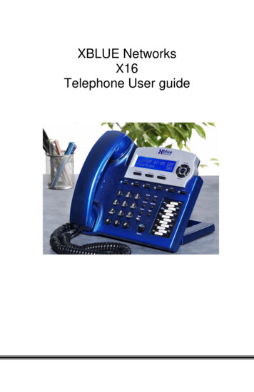
1. Speed Dial Feature Keys . Eleven (11) programmable onetouch keys used for speed dialing2. Disconnect Key . Used to disconnect the line, exitthe store programming.3. Store Key .Used to program features andspeed dialing keys.4. Pause Key .Used to program a delay in speeddialing.5. Redial Key . Redials the last number dialed.6. Flash Key . .Provides a 100mS to 1000mStimed line break (programmable).7. Mute Key . .Key that disables the handset andspeaker phone microphones forprivacy.8. Numeric Dial Pad .Used for dialing.9. Hold Key . Lighted key usedcallers on hold.10. Headset ON/OFF Key .Key used to turn the headset ONor OFF. With LED Indicator.11. Speaker Key . . .Used to turn the speakerphoneON or OFF.12. Volume Bar . .Adjustshandsetand/orcontrast13. HandsetHearing-aid compatible handset. . .TM14. TouchliteKey. .7forplacingthe loudness of thereceiver, the headset,thespeaker.Adjustsof the LCD Display.Message Waiting Lamp (LEDindicator) that blinks to indicatea new message in the user’s voicemail box (user must be subscribedto a messaging system).
RIGHT SIDELEFT SIDEREAR8
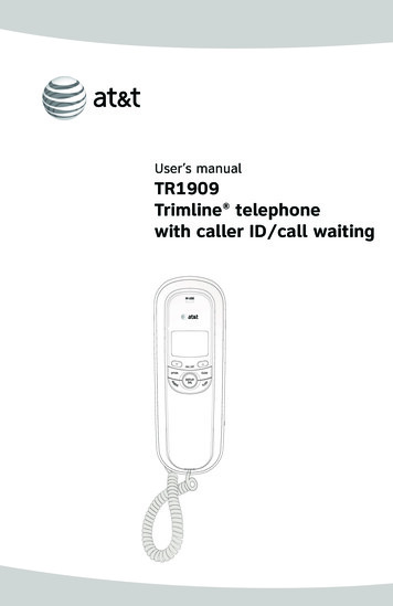
1.Data Port . Convenient port to connect acomputer, modem, fax oranswering device.2.Line Jack .Modular receptacle forconnecting the line cord.3.Headset Jacks .Convenient RJ port or 2.5mmcoaxial port used to connectan optional headset.4.Handset Jack . Connection for handset coilcord.5.Volume Control Switch . . Ring Volume control optionsof High/Low/Off.6.Message Waiting Light Switch 7.Hold Key Switch . Used to select standard linehold or programmable systemhold.8.Elevation Stand Lock Used to “lock” the elevationstand in place.9Neon or LED switch setting
Parts Check ListThe following parts are included with the Spectrum PLUSTM LP550:1.2.3.4.5.6.7.8.Base UnitHandset15-foot modular telephone line cord.10-foot modular coiled handset cord.6-inch modular wall mount line cord.Twenty-two (22) Speed Dial Preprinted Keycaps.Four (4) Additional Clear Keycaps.Two (2) Index Sheets.NOTE: SpectrumPLUSTM Line Cords are 6-Pin 6-Conductor Line cords(6P6C line cord). Replacement Line Cords must be same.10
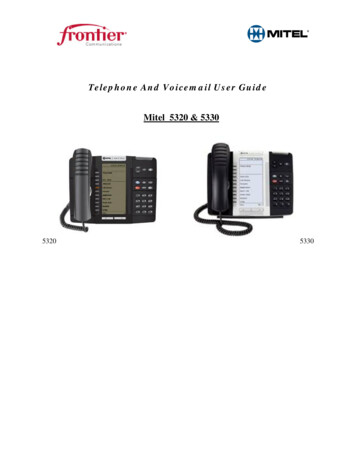
Caution Never install telephone wiring during a lightning storm. Never install telephone jacks in wet locations unless the jack isspecifically designed for wet locations. Never touch uninstalled telephone wires or terminals unless thetelephone line has been disconnected at the network interface. Use caution when installing or modifying telephone lines.Line Power ConfigurationThe Spectrum PLUS TM Seriestelephone does not require externalpower. It uses line power from thetelephone company. Simply plug inthe line cord from the wall jack tothe back of the telephone.Completing the PowerInstallationIf the installation is correct, theinformation shown at the right willbe displayed on the LCD.If the LCD does not display wordsand numbers, check your line cordconnections.1102/27pm12:260000NEWTOTAL
Connecting the Handset CordA 10-foot modular coil handset cord isprovided. (Be sure that the wall/deskelevation stand has not been attached).To install the cord, simply plug the shortend of the handset cord into the modularjack on the handset. The long end of thehandset cord plugs into the jack labeled“Handset” located on the bottom of theSpectrum PLUSTM base unit. Route thehandset cord into the handset coil cordchannel located directly below the jack.Installing the KeycapsTwenty-two silk-screened named featurekeycaps are provided to identify thespeed dial key.There are eleven (11) clear keycapsalready installed. To install pre-printedkeys, remove the clear keycap by simplypulling up. Replace with the pre-printedkeycaps or place user printed paperindex sheets under a clear keycap.Program each speed dial key for the specific function of the key.NOTE: For speed dial programming instructions, see the section on “Programming Procedure ForSpectrum Plustm Speed Dial Features” in this manual.There are four additional clear keycaps and two index sheets provided asspares. Use these for your own personal speed dial identities. Hand write orprint the speed dial name(s) on the blank speed dial index cards and insert intothe blank keycaps. Place the keycap on the correct memory speed dial location.(see index sheets provided in box).The twenty-two silk-screened keycap names are below:Call Fwd OnCall Fwd OffTransferConfDNDCall BackCancel Call BackCall ParkCall Pick-upGroup Call Pick-upPagingRing AgainSave MsgDel MsgRpt Msg12Skip MsgFF MsgRew MsgEmergencyHelp DeskInformation911
Wall Mounting the Spectrum PLUSTM TelephoneThe Spectrum PLUSTM was designed to beconveniently wall mounted without requiringadditional hardware.1.LIFT CLIP OUT WITHFINGERS. IT CANNOTBE REMOVED1.U NBECAUSES NA P2.ROTAT E 1 80IT IS SPRINGLOADED.3.Follow these easy steps:RETAINER CLIPNOTE: CLIP IS SPRINGLOADED.SN AP I NT O P LA C E.2. RTATE THECLIP 1800 ANDIT WILL SMAPBACK INTO THE OPPOSITE POSITION. ANEXTENDED PLASTICBUMP WILL BE FACE-UPFOR WALL MOUNTING 1.The handset retaining clip must be in thecorrect position to secure the handset into thehandsetcradle. Engage the clip with yourfingers and pull the clip forward (towards you),rotate the clip 180º and snap the clip back intoplace (figure 1). The retaining clip cannot beremoved.figure 1Replace Mounting Wedge2. The Spectrum PLUSTM mounting wedge mustbe correctly positioned. This wedge allows thetelephone to be viewed at a correct anglewhen the phone is wall mounted. Remove thewedge from the phone base (figure 2).3. Secure the line cord, coil cord and anywiring in place prior to installing the wallmount wedge. The wall mount base has extralarge wiring channels and strain relief poles forcontaining the wires in a neat and orderly way.Wrap the wires around the strain relief polesand then secure the wires through thechannel.figure 2Replace Mounting Wedge4. To install the wall mount, place it’s narrowedge at the top edge of the phone base andslide the wedge upward into place (figure 3).figure35. Lock the wall mount into position by slidingthe locking button to the right (figure 4).Lock Mounting Wedge!Note: A 6-inch line cord is provided for whenthe telephone is to be wall mounted. Connectone end of the line cord to the phone jack andthe other end to the wall jack.Desk Mountingfigure 4To install the wedge for desk mounting, be sure the lock mechanism is positioned to theleft clear of the locking arm. Place the wedge in the slots, wide end toward top of phonebase unit, and slide the wedge upward into position. Lock the wedge into place.13
Message Waiting Light IndicatorMessage Waiting Light IndicatorThe Spectrum PLUSTM telephone has aMessage Waiting (MW) Light Indicator(figure 1). The indicator will blink toindicate that a new message is in theuser’s voice mailbox. The SpectrumPLUSTM supports the following PBXsupplied message waiting signals:1.VMWI Service* (FSK signal compatible subscription is required).2.Or, Audible Stutter Dial Tone (SDT)signals provided by local telephonecompany.3.Or, 90-Volt NEON message waitinglight indicator signal provided by aPBX.2. Or, Low Voltage LED message waitinglight indicator light signal is providedby a PBXThe PBX system provider has to activatethe voice mail feature for the light toilluminate and work properly. Be surethat your PBX system has the compatiblemessaging service available in your areaor facility.figure 1!NOTE:Thistelephoneisdesigned to operate behind aPBX which provides NEON/LEDsignaling. The LED signal suppliedby a PBX must have the LED Voltage switch which is located on theback of the telephone in the correctposition to operate the LED. Seethe next page for instructions.FSK/SDT signaling is provided by atelephone operating company andthis telephone will read the CO signaling.Feature Note: Message ON/OFF Notification.fUse this feature when alerting another that a saved message is in voice mail for that person oruse this feature when you simply want to turn the light off.Be Aware: If there is a new incoming message and the telephone company continues to senda new signal this light will re-activate. This will occur only when there is a new voice mail thathas not been heard.How To Use: When on-hook, Press the “*” key for 3 to 5 seconds and the Message LED willautomatically turn on. At any time press “*” key for 3 to 5 seconds ,Message LED will turn off.d*Definition: VMWI is Visual Message Waiting Indication. This option requires a subscription to your local service provider for TouchLiteTM to activate.14
Low Voltage LED SwitchA low voltage LED switch is located onthe bottom of the phone. The switchoptions are ON or OFF. The factorydefault is OFF.System Hold FeatureOption SwitchA feature switch for different holdfunctions is located on the bottom ofthe phone. The switch options arestandard “LINE Hold” or programmable “System Hold”*.The standard “Line Hold” allows fornormal hold function operation. Theprogrammable “System Hold”* featureis used for optional PBX system * To programming System Hold is anAdministrator function. To programoperations.System Hold, followthe speeddialThe switch default is set at the factory instructions in this manual. To store thedialing pattern, press the HOLD key inas standard “LINE Hold”.place of the memory location.Ring Volume SwitchThe ring volume switch can be set atHigh, Low or OFF position. The ringvolume switch provides a fixeddesired ring volume.15
Programming Procedure for Spectrum PlusTM Speed Dial Features(Manual Entry of Characters)The Spectrum PLUSTM Telephone has eleven (11) one-touch speed dial locations that areconvenient for dialing frequently used telephone numbers. This feature is under Administrative control so user changes do not occur. Speed dial programming must be done with the telephone plugged into the telephoneline and power adapter.Programming can be performed with the telephone on-hook only.A maximum of 32-digits can be entered into ENTER NUMBER and 12-characters intoENTER NAME.ENTER NUMBERENTER NAMESet up speed dial memory locations with nameand number entries.Check verifies correctentry.12/01PM12:00ENTER ACCESS NO.To Program Speed Dial LocationsFigure 11. Press and hold the “STORE” key. (figure 1).2. Next, press the speed dial location key wherethe desired location will be (figure 2).3. Press the “STORE” key again (figure 3).4. Using the dial pad, enter the number. Note thatthe local area code is not required if AREACODE is pre-programmed into memory.5. After entering the number, press the “STORE”key. (figure 4).6. Using the keypad, enter the name associatedwith the number being programmed and includethe Flash, and/or Pause, when needed.7. Press the “STORE” key to store the entry.8. To program other speed dial locations, repeat 2to 7.9. To exit the program mode, press “DISC”.12/01PM12:00M01 NO CONTENTFigure 212/01PM12:00ENTER NUMBERFigure 312/01PM12:00ENTER NAMEFigure 416
Manual Entry From Keypad (Guide)Use the following chart to add characters when programming esNo. 11No. 2ABC2No. 3DEF3No. 4GHI4No. 5JKL5No. 6MNO6No. 7PQRSNo. 8TUV8No. 9WXYZ9No. 00No. *addsspace *No. #.:—()17FiveTimesSixTimes7#
Programming Set Up Of the Spectrum PLUSTM TelephoneThe Spectrum PLUSTM requires simple initial programming to set up the telephone.The Quick Program Guide for the Spectrum PLUSTM TelephoneThe Spectrum PLUSTM Quick Programming Guide is a summary list of set up options.Additional detailed instructions are provided in the manual.Programming is initiated by pressing the“STORE” key.Set up pre-dialing number sequence, i.e. outside line.Set up local area codetorecognizelocalincoming calls.STOREENTER ACCESS NO.VOICE MAIL NO.ENTER AREA CODESETUP MONTH:01PIN NUMBERSETUP DAY:01SECOND OF WAIT?Set up date and timeAM 1SETUP HOUR:01PRESS 1 ON 2 OFFSETUP MINUTE:01Set up flash timing100mS to 1000mS.Default 600mS.Set up pause timing1.0S to 5.0S. Default3.6S.-1ENGPIN numbercharacterswill not bedisplayedon the LCD.PM 2LIVE DIALPAD XXXSet up languageSet up voicemail number.Add your PINwith secondsof wait timeto get accessto messages.-2FRAALL SETUP OK-3ESPFLASH TIME SETPAUSE TIME x.x S18Set up eitherusing keypaddialing withAutomaticspeaker activation, or usingkey pad dialing,pressing dialkey to activate.
Programming the Area Code into MemoryAn Area Code can be programmed into the phone memory at the option of theAdministrator. The Area Code is programmed into memory to allow the phone torecognize the local area code. When this number is programmed, the Are CodeWILL NOT be dialed when calling back a number within the same local callingarea.Set up local area codeto recognize local incoming calls.ENTER AREA CODE12/01PM12:00719 - ENTER AREA CODEProgramming the Area Code into Memory1. Press the “STORE” key the programming mode.2. Press the “STORE” key multiple times until “ENTER AREA CODE” isdisplayed.3. Enter the area code number of the local area code using the numeric dialpad.4. Press the “STORE” key to store the area code into memory.5. To exit the program mode, press “DISC” or continue to the end ofprogramming by pressing the “STORE” key multiple times until the displayreads “All Setup OK”.In some areas, the Area Code is required when placing a Local CallIn some areas, the local service provider will use the same area code for localcalls. The following options are available.Try each of the following scenarios and use the one with the best result.1. Program the Area Code first, then place a local test call.2. Delete the area code and do not program the Access Code. Place a localtest call.3. Program the Area Code into the Access Code location. Place a local testcall.4. Use the keypad to add additional numbers to the displayed number onthe screen. Place a local test call.!NOTE: Depending on your area and dialing pattern, you may obtain the best resultby using both the access code and area code fields. If these sequences do not work,use the keypad entry as an option for your Call Back.19
Programming the Access Number into MemoryIn some cases, a digit or digits are required to access an outside line (i.e. 9).The Access Number can be programmed into the phone memory at the optionof the Administrator. This function allows the user to automatically dialnumber(s) that are required prior to dialing the displayed number. The number to be programmed is based on your specific area dialingrequirements and may not be required.This option is not mandatory for the proper operation of the Caller IDdisplay.Set up pre-dialing number sequence, i.e. outside!ENTER ACCESS NO12/01Note: Programming canonly be performed whenphone is on-hookPM12:009---ENTER ACCESS NO.To Set Up The Access Number1.2.3.4.PressPressEnterPressthe “STORE” key to enter the programming mode.“STORE” until the LCD display reads “ENTER ACCESS NUMBER”.the desired number, for example, a “9”.the “STORE” key to enter the number into memory.!NOTE: There is no need to enter PAUSE. The Call Back operation automatically inserts a pause after the AccessCode Number.To Delete The Access Code1. Press the “STORE” key to enter the programming mode.2. Press the “STORE” key until the LCD display reads “ENTER ACCESSNUMBER”.3. Press the “DELETE” key.4. Press the “STORE” key again to continue.20 page
includes advanced features that are suitable in today’s business environment. TeleMatrix has designed the LP550 to be simple to install and easy to use. The LP550 is designed to be used behind a PABX. It is recommended to install one phone in-line (one