Transcription
Installation GuidelinesFor Electrofusion Couplings14” and LargerTN-34/2009105 Decker Court, Suite 825, Irving, TX 75062 P: 469-499-1044 F: 469-499-1062 www.plasticpipe.org
ForewordThis report was developed and published with the technical help and financial support of the members of the PPI(Plastics Pipe institute). The members have shown their interest in quality products by assisting independentstandards making and user organizations in the development of standards, and also by developing reports on anindustry-wide basis to help engineers, code officials, specifying groups, and users.This report has been prepared by PPI as a service of the industry. The information in this report is offered in goodfaith and believed to be accurate at the time of its preparation, but is offered without any warranty, expressed orimplied, including WARRANTIES OF MERCHANTABILITY AND FITNESS FOR A PARTICULAR PURPOSE.Any reference to or testing of a particular proprietary product should not be construed as an endorsement by PPI,which does not endorse the proprietary products or processes of any manufacturer. The information in this reportis offered for consideration by industry members in fulfilling their own compliance responsibilities. PPI assumesno responsibility for compliance with applicable laws and regulations.PPI intends to revise this report from time to time, in response to comments and suggestions from users of thereport. Please send suggestions of improvements to the address below. Information on other publications can beobtained by contacting PPI directly or visiting the web site.The Plastics Pipe InstitutePhone: (469) 499-1044http://www.plasticpipe.orgOctober 2009
Installation Guidelines for Electrofusion Couplings 14” and LargerA. Safety:Jobsite safety requirements should be fully understood and observed.Electrofusion fittings and equipment are not intended to be, and are not “Explosion Proof”. If used in avolatile environment, additional ignition concerns may be present and are not addressed in thisdocument.When moisture at the fusion site is a safety concern, connect the leads to the fitting before the controlunit is powered up. Take safety precautions to prevent exposure to electrical shock hazards.B. Operator Experience:Electrofusion couplings should only be installed by persons that have received training from anauthorized electrofusion instructor, that have a strong working knowledge of polyethylene and heatfusion, and have qualified 14” and larger electrofusion joints through destructive testing. This documentis a guide only, and should not be used in place of training by an authorized electrofusion instructor.Failure to follow all preparation steps can result in joint failure or leakage due to contamination orimproper installation.Destructive tests are described in ASTM F1055-98 (2006) and can be in the form of burst tests, bendtests, peel tests and other methods useful in determining the quality of a fusion joint. (See Job AidAppendix A for additional information).C. Pre-installation Requirements:1. Pipe Diameter – Some electrofusion manufacturers have specific dimensional requirementsfor pipe that is to be joined using electrofusion couplers. Verify that the pipe to be joined meetsthe electrofusion manufacturer’s requirements for optimum fusion. In the absence of specificdimensional requirements ensure that the pipe diameter is within the tolerances, at thespecified temperature, of the applicable pipe standard (ASTM F714, AWWA C906, etc.).Standard tolerances are determined at 73 F. Measure pipe diameter with a Pi tape (see JobAid Appendix A) at 2” and 6” from the pipe end to determine diameter. Pipe toe-in or reductionin diameter, is a condition that occurs at the pipe end and should be checked to ensure thatthe pipe diameter is within tolerance at 2” from the end. Severe toe-in may require the removalof up to one pipe diameter or 12” from the pipe end. In preparing a pipe for electrofusion thepipe OD is reduced by at least .014” by scraping the outside surface. This OD reduction shouldbe taken into consideration when accepting pipe extruded close to the above minimumtolerances.
.1. Pipe Ovality - Determine if an ovality condition exists: Measure the pipe diameter to determinethe amount of out-of-roundness. if ovality exceeds 2%, re-rounding clamps must be used .2. Pipe ends should be squarely cut to 90 5 . A 4” or wider sling or strap can be used as a guideto mark the pipe for cutting (see Job Aid Appendix B). A level and protractor can be used todetermine the angle of the cut.3. Pipe alignment – Pipe alignment should be inspected to ensure that no stresses are present inthe assembly that might cause movement during fusion.4. Power Source – An adequate power source is required. Ensure that power source is capable ofdelivering power for entire coupling fusion time without interruption (check generator for full fuelsupply). Ensure that all connections are tight and clean. Loose connections can result in arcingor blown fuses.a. 110 Volt: A minimum 5000 watt continuous supply generator capable of delivering 115volts to 135 volts at 45 Hz to 66 Hz to the control box. Minimum 30 amp breaker with“slow blow” or time delay fuse. 30 amp twist-lock Nema L5 receptacle.b. 220 Volt: A minimum 5000 watt continuous supply generator capable of delivering180 volts to 300 volts at 45 Hz to 65 Hz to the control box. Minimum 30 amp breakerwith “slow blow” or time delay fuse. 15 amp twist-lock NEMA L6 receptacle.Note: Commercially available generators capable of meeting these requirements areusually in excess of 7500 watt capacity and need to be in good working order.5. Extension Cords – Typically, a single extension of up to 50’ is permitted between the generatorand the control box. The minimum wire gauge is 10/3 awg for extension lengths up to 50’.Longer lengths may be allowed, consult the fitting and equipment manufacturer for specificrecommendations.6. Control Box – A 24 digit barcode compatible control box conforming to ISO 12716 must be usedto deliver the required energy to the coupling.a. The control box must be capable of delivering 80 amperes at 40 volts output.b. The control box must be capable of reading the coupling barcode and applying the correctfusion parameters, including automatic temperature compensation, to the fitting withoutoperator intervention.c. The control box must be capable of reading ambient temperatures at the fusion site.7. Scraping Tools – PIPE PREPARATION IS VERY CRITICAL TO THE ELECTROFUSIONPROCESS. CAREFUL ATTENTION MUST BE GIVEN TO PROPER CLEANING AND
SCRAPING PROCEDURES TO REMOVE CONTAMINATION AND SURFACE OXIDATIONFROM THE PIPE SURFACE.a. Ensure that only mechanical type scraping tools designed specifically for electrofusionpreparation are used to prepare the pipe surface.b. Do not use abrasives such as grinders, emery cloth, or sandpaper.8. Markers – Ensure that insertion depth and pipe scrape area markings are made with a nongreasy, non petroleum based, fast-drying, permanent marker or paint pen.9. Cleaning agent / wiping cloth – A clean, dry, non-dyed, lint free cloth is used to clean pipesurfaces. 96% or higher Isopropyl alcohol without additive except water is recommended as acleaning agent. Pre-impregnated wipes without additives may also be suitable. Denaturedalcohol may contain other impurities and is not suitable for use with electrofusion. Under nocircumstances should a coupling fusion be made with any liquid (water, oil, sewage, etc.) flowingthrough the pipe or fusion area. Fusion joint failure and possible electrical hazards could occur.The fusion zone must be clean and dry before and during fusion.10. Weather Conditions – Observe manufacturer’s recommended minimum and maximuminstallation temperatures for electrofusion fittings.a. The typical installation temperature range is -4 F to 120 F (-20ºC to 49ºC), but can varyabove and below that range depending on the manufacturer. If ambient temperatures areoutside this range, consult the equipment and fitting manufacturer for a specificrecommendation.b. Large diameter couplings may use a temperature specific fusion time or a pre-heat cycleprior to fusion.c. Protect the fusion site in case of inclement weather such as rain or snow.D. Installation procedure:1. Clean pipe ends to remove dirt, mud, and other debris from pipe ends. Clean water can be usedfor initial cleaning prior to scraping; however, the pipe surface must be clean and dry beforescraping. Check pipe surface and remove any embedded debris that may cause damage toscraping tools. PIPE PREPARATION IS VERY CRITICAL TO THE ELECTROFUSIONPROCESS. CAREFUL ATTENTION MUST BE GIVEN TO PROPER CLEANING ANDSCRAPING PROCEDURES TO REMOVE CONTAMINATION AND SURFACEOXIDATION FROM THE PIPE SURFACE.
2. Ensure that the pipe end has a square and even cut as close to 90 as possible. A sling or strapcan be used as a guide for marking pipe ends for straight cutting.3. Measure the total length of the coupler to be installed. Make a mark (with recommended marker)from the pipe end that is 1/2 the total length of the coupler. This mark is for stab depth purposesand will ensure that the pipe end is inserted to the center of the coupler.
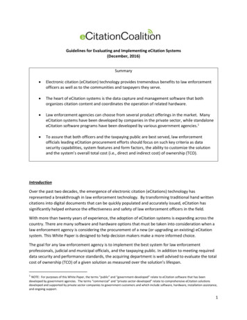
4. When measuring for pipe ovality, the High/Low diameter difference should not exceed 2%. Ifrequired, place a re-round clamp immediately outside the stab depth mark. Do not scrape toremove high sides of oval pipe in order to relieve ovality.Measure for highest and lowest diameter points, use re-round clamps if necessary.Re-rounding devices are either commercially available (below left) or can be substituted by using fullencirclement-type metal rings (below right).
5. Scrape the outside of the pipe surface to remove oxidation and other contaminants. Use amechanical type scraping tool designed specifically for electrofusion preparation toremove at least .014” (0.36 mm) from the pipe OD. Scrape the pipe surface until an outer layer or"skin" has been removed to expose clean, virgin pipe material. Inspect the entire circumference ofthe scraped area to ensure total scraping coverage. Do not touch the scraped surface you’re yourhands because it may introduce surface contamination. Scraped pipe should conform to thedimensional requirements of Table 1. Do not use abrasives such as grinders, emery cloth, orsandpaper6. Do not touch the scraped pipe surface or the inside of the coupler as body oils and othercontaminates will compromise fusion joint performance. If the surfaces become contaminated,clean thoroughly with a clean lint free towel and 96% isopropyl alcohol and allow to dry beforeassembling. Do not use alcohol with any additives other than water. CAUTION: DO NOT TOUCHTHE FUSION SURFACES TO AVOID ALL POSSIBLE RECONTAMINATION OF THECOUPLING AND PREPARED PIPE SURFACES.7. If coupler is to be pushed completely over one pipe end, scrape the pipe end for the entire length ofthe coupler to prevent contamination of the coupler by sliding over un-scraped pipe.
8. Install coupler onto the pipe ends so that the stab depth marks are aligned at the outer edges of thecoupler. The pipe ends may be beveled to allow for easier insertion into the coupling. Ifnecessary, use a rubber mallet (or metal hammer and wood blocks) to move coupler onto pipe.Re-round clamps can be used as anchors for pulling couplers onto pipe with mechanical assistdevices such as a hand winch. Use care not to damage internal wire or terminal pins. Leaveplastic bag over coupler to prevent contamination, and debris from entering the open end.9. Check pipe end alignment to ensure that there is no bind or stress exerted on the coupling beforeor during fusion and until cooling time has elapsed. Support for the pipe and coupling may benecessary to prevent stresses or sagging that may develop as heat is applied during fusion.
10. Make sure the generator is operating normally before powering the control box. Connect thecontrol box leads to the coupler. Make sure that all connections and lead adapter tips areproperly sized and secure.11. Scan the barcode to set the fusion time. Ensure that label information conforms to scanned data.Observe the manufacturer’s procedure for pre-heating or temperature specific fusion time. Startthe fusion process. Do not leave unattended. Depending on the coupling manufacturer, somecouplings have multiple barcodes that correspond to the ambient temperature, or a separate preheat barcode that is used prior to fusing the coupling. Follow the manufacturer’s recommendationfor scanning the proper barcode. Under no circumstances should a coupling fusion be made withany substance flowing through the pipe or fusion area. Fusion joint failure and possible electricalhazards could occur. The fusion zone should be clean and dry before and during fusion.
12. After the fusion cycle is complete, verify fusion cycle completion is normal. Check melt indicators ifthe coupling is so equipped. Note the cooling time and mark the time when the clamping time haselapsed on the pipe. Additional information such as fusion record ID number, control box serialnumber, etc. should also be recorded if required. For couplers with dual fusion zones, repeat forboth ends of the coupler. If a fusion cycle fault occurs, note the error code displayed by the control box and proceedaccording to the manufacturer’s recommendation. In case of power interruption, i.e. generatorruns out of gas, leads are disconnected, or any other power interruption failure, consult themanufacturer’s instructions for re-fusion. Faults caused by any other circumstances should notbe re-fused.13. Backfill and handling can be completed after the recommended minimum cooling time haselapsed. The recommended cooling time is displayed by the control box after the fusion cyclecompletes, or can be found on the coupler label. Pressure leak testing can be conducted after therecommended cooling time plus one hour has elapsed.
The f
Destructive tests are described in ASTM F1055-98 (2006) and can be in the form of burst tests, bend tests, peel tests and other methods useful in determining the quality of a fusion joint. (See Job Aid Appendix A for additional information). C. Pre-installation Requirements: 1. Pipe Diameter – Some electrofusion manufacturers have specific dimensional requirements for pipe that is to be .