Transcription
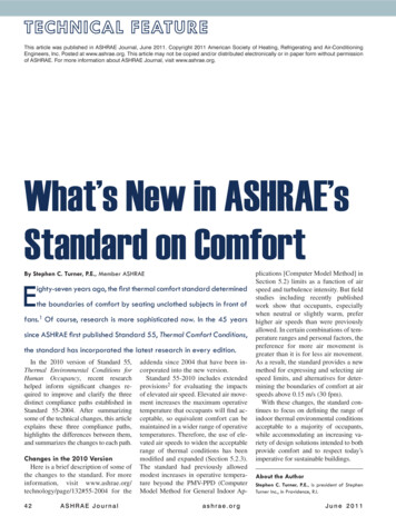
This article was published in ASHRAE Journal, June 2011. Copyright 2011 American Society of Heating, Refrigerating and Air-ConditioningEngineers, Inc. Posted at www.ashrae.org. This article may not be copied and/or distributed electronically or in paper form without permissionof ASHRAE. For more information about ASHRAE Journal, visit www.ashrae.org.What’s New in ASHRAE’sStandard on ComfortBy Stephen C. Turner, P.E., Member ASHRAEEighty-seven years ago, the first thermal comfort standard determinedthe boundaries of comfort by seating unclothed subjects in front offans.1 Of course, research is more sophisticated now. In the 45 yearssince ASHRAE first published Standard 55, Thermal Comfort Conditions,the standard has incorporated the latest research in every edition.In the 2010 version of Standard 55,Thermal Environmental Conditions forHuman Occupancy, recent researchhelped inform significant changes required to improve and clarify the threedistinct compliance paths established inStandard 55-2004. After summarizingsome of the technical changes, this articleexplains these three compliance paths,highlights the differences between them,and summarizes the changes to each path.Changes in the 2010 VersionHere is a brief description of some ofthe changes to the standard. For moreinformation, visit www.ashrae.org/technology/page/132#55-2004 for the42ASHRAE Journaladdenda since 2004 that have been incorporated into the new version.Standard 55-2010 includes extendedprovisions2 for evaluating the impactsof elevated air speed. Elevated air movement increases the maximum operativetemperature that occupants will find acceptable, so equivalent comfort can bemaintained in a wider range of operativetemperatures. Therefore, the use of elevated air speeds to widen the acceptablerange of thermal conditions has beenmodified and expanded (Section 5.2.3).The standard had previously allowedmodest increases in operative temperature beyond the PMV-PPD (ComputerModel Method for General Indoor Ap-plications [Computer Model Method] inSection 5.2) limits as a function of airspeed and turbulence intensity. But fieldstudies including recently publishedwork show that occupants, especiallywhen neutral or slightly warm, preferhigher air speeds than were previouslyallowed. In certain combinations of temperature ranges and personal factors, thepreference for more air movement isgreater than it is for less air movement.As a result, the standard provides a newmethod for expressing and selecting airspeed limits, and alternatives for determining the boundaries of comfort at airspeeds above 0.15 m/s (30 fpm).With these changes, the standard continues to focus on defining the range ofindoor thermal environmental conditionsacceptable to a majority of occupants,while accommodating an increasing variety of design solutions intended to bothprovide comfort and to respect today’simperative for sustainable buildings.About the AuthorStephen C. Turner, P.E., is president of StephenTurner Inc., in Providence, R.I.a s h r a e . o r gJune 2011
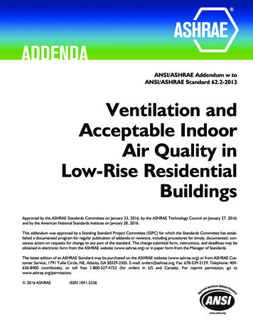
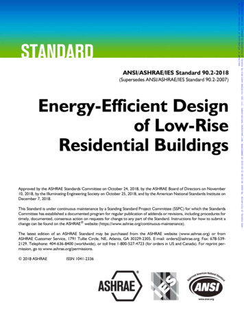
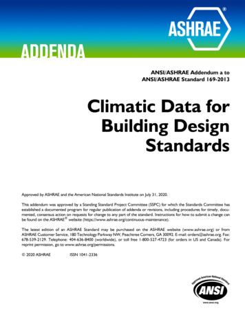
The maximum permissible operative temperature increases dramatically from traditionalstill-air comfort zones. Two important notes: thepermissible air speeds for cooler temperatureswithout local occupant control have not changed,and for a certain elevated air speed the lower limit on temperature increases as well, not just theupper limit.The standard clarifies that the upper humiditylimit shown on the psychrometric chart in thegraphical method only applies to the GraphicComfort Zone Method for Typical Indoor Environments (Graphic Comfort Zone Method).Higher humidity limits are allowed if evaluatedwith the Computer Model Method, and no limitsare imposed on the Adaptive Method.Figure 1: Acceptable range of operative temperature and air speeds for theRevised requirements and calculation meth- comfort zone shown in Figure 2, at humidity ratio 0.010 (Standard 55-2010).ods apply when increased air movement is usedto maintain comfort in warm conditions. Standard Effective tions in Naturally Conditioned Spaces (Adaptive Method).Temperature (SET) is re-introduced into the standard as the The Graphic Comfort Zone Method is the simplest, the timecalculation basis for determining the cooling effect of air honored Graphic Method based on the (in?)famous thermalmovement. This calculation method has been simplified with comfort chart. It is based on the Computer Model Method, butthe removal of turbulence intensity and draft risk calculations minimizes calculations. It includes a “comfort zone” graphicand the personal control limitations have been relaxed based in the standard that applies to projects where the assumptionson the results of new research. This change is expected to give and limitations stated in the method apply.clear requirements for application of ceiling and other inThe second method is the Computer Model Method, whichroom fans for comfort cooling.requires calculations that allow—and require—the use ofSection 6, Compliance, contains new mandatory minimum project specific inputs. This method applies to some projectsrequirements for analysis and documentation of a design to or spaces not suited for the graphic comfort zone method. Theshow that it meets the requirements in the standard. Informa- third method is the Adaptive Method introduced in 2004 totive Appendix G expands on Section 6, Compliance, by pro- extend the applicability of the standard to naturally ventilatedviding a compliance form for documentation of design com- spaces. This approach is for use in naturally ventilated spacespliance. This form is the basis for the U.S. Green Building without mechanical cooling, and applies to times when noCouncil LEED template for documenting compliance with heating system is in use. In such projects and conditions, itthe requirements of the Thermal Comfort design credit in the better describes the range of thermal conditions that provideNew Construction (NC) rating system’s Indoor Environmental comfort as occupants “adapt” to changing outdoor conditions.Quality Credit 7.1.A new general satisfaction survey has been added to Section Graphic Comfort Zone MethodIn the past, I attended many ASHRAE chapter programs7.5.2.1 as a method to evaluate thermal comfort in occupiedspaces. The previous survey in the 2004 version of the stan- that incorporated a scanned version of the tiny chart that apdard was meant for evaluating comfort at a point in time (e.g., peared in earlier versions of the standard. This was invariably“how do you feel right now?”), and the new survey is meant to presented with misinformation or missing information aboutevaluate the overall comfort of a space (e.g., “how do you feel the related requirements of the standard. Unfortunately, anin general?”). Addition of a general satisfaction survey aligns evaluation of compliance documentation examples collectedStandard 55 with current practice for survey based post-occu- and reviewed by the committee in recent years shows similar oversimplification of design for compliance with Standardpancy evaluations (POEs).Editorial changes have been made throughout the standard 55. To help improve compliance with the Graphic Comfortto clarify requirements. Wherever possible, the use of infor- Zone Method and all of its requirements, the committee hasmade significant editorial improvements to the comfort zonemative language in the standard is avoided.graphic.Compliance Paths & Methods in Standard 55-2010Today, the improved and enlarged comfort zone graphicAs with the 2004 standard, there are three primary com- (Figure 1) in the 2010 standard better represents the sevpliance paths in Standard 55-2010: the Graphic Comfort eral conditions and opportunities related to this complianceZone Method, the Computer Model Method, and the Op- method. Foremost, this graphic cannot be applied based ontional Method for Determining Acceptable Thermal Condi- dry-bulb temperature alone! As is true in all three complianceJune 2011ASHRAE Journal43
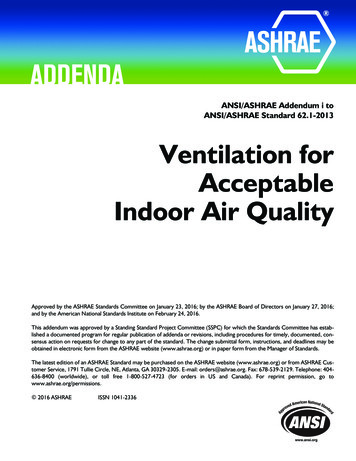
Figure 2: The new Graphic Comfort Zone Method, Figure 5.2.1.1 in Standard 55-2010 (IP version shown).paths, and indeed in much of the standard, the graphic represents operative temperature.The standard in certain cases allows air or space temperature to be used as an approximation for operative temperature, but only in spaces where mean radiant temperature doesnot unduly depart from air temperature. Appendix C of thestandard provides more detail on when this simplifying approximation is justifiable. In today’s architecture with abundant glazing, this simplifying assumption may not always apply. So, the building and its systems must be able to provideoperative temperatures in the ranges shown, at and betweenthe warmer and colder outdoor design conditions applicableto the project.The upper limits for humidity with this simple GraphicComfort Zone Method are more strict than with the othercompliance paths. An upper limit of 0.012 humidity ratio applies, which gives us the “flat top” of the comfort zone in Figure 1. For the “summer” comfort zone based on lightweightclothing towards the right side of the figure, this representsrelative humidities between 67% and 56%. Bear in mind that,44ASHRAE Journalwith respect to humidity, ANSI/ASHRAE Standard 62 is morerestrictive than Standard 55, which does not deal with IAQ northe impact to building materials and envelopes.Additionally, as is now stated in the graphic, the requirements of Sections 5.2.3 through 5.2.5.2 must be met. Thoughpreviously true, these requirements were often ignored in design processes and documentation evaluated by the committee. These sections require that, in addition to being able toachieve operative temperatures within the applicable comfortzone, designs claiming compliance with Standard 55-2010must also address specific limits and provisions for evaluatingthe impacts of elevated air speed (§5.2.3), as well as the following causes of local thermal discomfort: Radiant temperature asymmetry (§5.2.4.1); Draft (§5.2.4.2); Vertical air temperature difference (§5.2.4.3); and Floor surface temperature (§5.2.4.4).Perhaps most often overlooked, are requirements limitingtemperature variations with time: cyclic variations (§5.2.5.1)and drifts or ramps (§5.2.5.2). As stated previously, the elevata s h r a e . o r gJune 2011
Advertisement formerly in this space.
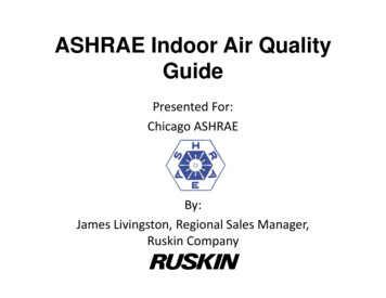
Evaluating Acceptable Thermal Conditions Using Standard 55-2010StepEvaluation QuestionIf YesIf No1Are expected met rates between 1.0 and 1.3 met and are expected clo valuesbetween 0.5 and 1.0 clo, to meet the limitations of the graphical method inSection 5.2.1.1?Proceed to Step 3Proceed to Step 22Are expected met rates between 1.0 and 2.0 met and are expected clo values 1.5or less, to meet the limitations of the computer model method in Section 5.2.1.2?Proceed to Step 4Unless space compliesunder Table 2 method for“Naturally conditionedspaces,” Standard 55-2010does not apply.3Is operative temperature, determined per Section 7 & Appendix C, withinacceptable ranges in Figure 5.2.1.1-1 for expected clo value, per GraphicalMethod Section 5.2.1.1?Proceed to Step 5Same as Above4Are assumed values for clo, met, design, air temperature, mean radiant temperature, relative air velocity, and relative humidity or water vapor pressuresuch that calculated PPD is under 10% (calculated PMV range is between–0.5 and 0.5), per Computer Model Method Section 5.2.1.1?Proceed to Step 6Same as Above5Is humidity ratio controlled to below 0.012, per Humidity Limits, Section 5.2.2?Proceed to Step 6Use computer methodor adaptive method,if applicable.6If any increased air temperature or mean radiant temperature is expected,does elevated air speed offset this, per Elevated Air Speed, Section 5.2.3?Proceed to Step 7Same as Above7Will wall and ceiling temperatures be within limits in Table 5.2.4.1, or is PD lessthan 5% using Figure 5.2.4.1, per Radiant Temperature Asymmetry Section5.2.4.1?Proceed to Step 8Same as Above8Will draft be within limits for air temperature and air speed per Section 5.2.4.2, orare elevated air speed requirements of Section 5.2.3 including local control met?Proceed to Step 9Same as Above9Will temperature difference taken from ankle to head level be less than 3 C(5.4 F), per Vertical Air Temperature Difference Section 5.2.4.3?Proceed to Step 10Same as Above10Will the floor temperature be between 19.0 and 29.0 C (66.2 and 84.2 F), perFloor Surface Temperature Section 5.2.4.4?Proceed to Step 11Same as Above11Are there any expected changes in operative temperature with periods under15 minutes less than 1.1 C (2.0 F), per Cyclic Variations Section 5.2.5.1?Proceed to Step 12Same as Above12Are any components of variations in operative temperature with periods over15 minutes within the respective limits in Table 5.2.5.2, per Drifts or RampsSection 5.2.5.2?Proceed to Step 13Same as Above13Must be completed to meetHave design and documentation compliance requirements in Section 6 beenRecommendations inrequirements of Standardmet (see Appendix G for compliance documentation forms)?Standard 55-2010 are met.55-2010.Table 1: Use this table for evaluating compliance using Section 5.2, the Graphic Comfort Zone Method for Typical Indoor Environmentsand the Computer Model Method for General Indoor Application, for spaces being served by heating and mechanical cooling systems.ed air speed provisions can be applied when using the Graphical Comfort Zone Method.Computer Model MethodThis method is the basis for the comfort zones drawn in theGraphic Comfort Zone Method, derived from the PredictedMean Vote (PMV) and Predicted Percent Dissatisfied (PPD)indices developed by the late Professor Ole Fanger in his seminal doctoral thesis (first published in book form in 1970). Theuse of these indices as the basis for this method makes Standard 55-2010 consistent with ISO Standard 7730. The com46ASHRAE Journalputer code that calculates these indices is in Appendix D ofthe standard, and is widely available from other sources. Thisapproach allows users of the standard to predict the extent towhich comfort will be provided based on a specific set of expected clothing level (clo), activity level (met), air temperature, radiant temperature, air speed, and humidity.The same additional requirements enumerated above for theGraphic Comfort Zone Method also apply to the ComputerModel Method; the only difference is that instead of an absoluteupper limit on humidity ratio, calculated limits pertain that allow, in certain conditions, even higher humidity. As stated previa s h r a e . o r gJune 2011
Evaluating Acceptable Thermal Conditions Using Standard 55-2010StepEvaluation QuestionIf YesIf No1Are thermal conditions of the space regulated primarily by the occupants through opening and closing of the window?Proceed to Step 2Unless space complies under Table 1method, Standard 55-2010 does not apply.2Is space equipped with operable windows that open to the outdoors andProceed to Step 3that can be readily opened and adjusted by the occupants of the space?Same as Above3Will the building be free of mechanical cooling systems (e.g., refrigerated, radiant, or desiccant)? (only mechanical ventilation allowed)Proceed to Step 4Same as Above4Is this method applied only for times when heating systemis not in operation?Proceed to Step 5Same as Above5Are expected met rates between 1.0 and 1.3 met and may occupantsProceed to Step 6freely adapt their clothing to indoor and/or outdoor conditions?Same as Above6Is operative temperature for each occupied space, determined perSection 7 & Appendix C, within acceptable ranges for 80% in Figure5.3-1 for mean monthly outdoor air temperatures, per OptionalMethod for Naturally Conditioned Spaces Section 5.3?Proceed to Step 7Same as Above7Have design and documentation compliance requirements in Section6 been met (see Appendix G for compliance documentation forms)?Recommendationsin Standard55-2010 are met.Must be completed to meetrequirements of Standard 55-2010.Table 2: Use this table for evaluating compliance using Section 5.3, the Optional Method for Determining Acceptable ThermalConditions in Naturally Conditioned Spaces (Adaptive Method), where thermal conditions of the space are regulated primarilyby the occupants through opening and closing of windows.Advertisement formerly in this space.June 2011ASHRAE Journal47
ously, with respect to humidity limits, ANSI/ASHRAE Standard62 is more restrictive than Standard 55, which does not deal withIAQ nor the impact to building materials or envelopes.As stated above, the elevated air speed provisions can beapplied when using the Computer Model Method.The Adaptive MethodWhen Standard 55 added the Optional Method for Determining Acceptable Thermal Conditions in Naturally ConditionedAdvertisement formerly in this space.Spaces method (Adaptive Method) found in section 5.3 in the2004 version, it was the first national or international standardto do so. Subsequently, ISO 7730 and others have likewise offered this important approach to designers. Standard 55-2010brings no changes to this method. Refinements to this methodand its underlying calculation are in progress, and will soon bepublished as an Addendum to Standard 55.As with the 2004 version, this method accommodates thedesign of naturally ventilated buildings. In these buildings,occupants are comfortable over an evenwider range of thermal conditions thancan be predicted by chamber studies orfield studies of occupants of climatecontrolled buildings. This method recognizes the role not only of adaptivity but ofself-mitigating strategies such as openinguser-accessible windows.While the elevated air speed provisionsdo not apply to the Adaptive Method,Standing Standards Project Committee55 has processed forthcoming changes tothe Adaptive Method to introduce theseprovisions within the Adaptive Method.What All This Means for PractitionersUsers of the standard who take the timeto fully understand, appreciate, and properly apply the 2010 changes will be ableto propose dramatically different systemsfrom their competitors. The elevated airspeed provisions include attendant restrictions and requirements. The intentof these requirements is to allow systemsthat can deliver dramatic reductions ingross cooling requirements and associated energy consumption in exchange formodest local fan energy penalties.2Choosing the best of the three availablecompliance paths for the project at handis essential; fluency with the ComputerModel Method is increasingly importanton complex or high performance projects.The changes empower designers and operators alike to implement an importanthigh performance building precept: thereis more than just one way to provide foroccupant comfort, and it need not be as energy intensive as previously required.References1. Spengler, J.D., J.M. Samet, J.F. McCarthy. 2000. Indoor Air Quality Handbook. N.Y.:McGraw-Hill Professional.2. Arens, E., et al. 2009. “Moving air forcomfort.” ASHRAE Journal 51(5).48A S H R A E J o u r n a lJune 2011
Comfort Zone Method are more strict than with the other compliance paths. An upper limit of 0.012 humidity ratio ap-plies, which gives us the "flat top" of the comfort zone in . Fig-ure 1. For the "summer" comfort zone based on lightweight clothing towards the right side of the figure, this represents relative humidities between 67% and .