Transcription
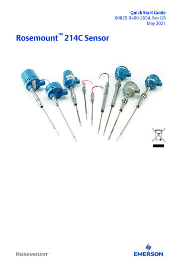
Quick Start Guide00825-0400-2654, Rev DBMay 2021Rosemount 214C Sensor
Quick Start GuideMay 2021ContentsAbout this guide.3Wiring diagram for RTDs. 5Wiring diagram for thermocouples. 6Additional RTD specifications. 7Additional thermocouple specifications. 9Product certifications. 10Declaration of Conformity.23China RoHS. 252Emerson.com/Rosemount
May 20211Quick Start GuideAbout this guideThis guide provides basic guidelines for Rosemount 214C Sensor models. Ifthe sensor was ordered assembled to a temperature thermowell ortransmitter, see the appropriate product literature for information onconfiguration and hazardous locations certifications.1.1Safety messagesNOTICEComplications can arise when the sensors and the transmitters to which theyare assembled are certified to compatible, but each has different approvals.Be aware of the following situations: If an I.S. approved Rosemount 214C Sensor is ordered with a housing, atransmitter enclosed in that housing may have a different I.S. approvalrating. Refer to the transmitter IS certificate if applicable. If a sensor and transmitter have different certifications, or if either hasmore certifications than the other, installation must comply with themost restrictive requirements required by either component. This isespecially (but not exclusively) relevant when combination approvals areordered on either the sensor or transmitter. Review certifications onboth the sensor and transmitter for installation requirements and ensureinstallation of the sensor/transmitter assembly complies with a singlecertification that is shared by both of these components and that meetsthe requirements of the application.WARNINGExplosionExplosions could result in death or serious injury.Installation of sensor in an explosive environment must be in accordancewith appropriate local, national, and international standards, codes, andpractices.Quick Start Guide3
Quick Start GuideMay 2021WARNINGConduit/cable entriesUnless marked, the conduit/cable entries in the housing use a ½–14 NPTthread form. Entries marked “M20” are M20 1.5 thread form. Ondevices with multiple conduit entries, all entries will have the samethread form. Only use plugs, adapters, glands, or conduit with acompatible thread form when closing these entries.When installing in a hazardous location, use only appropriately listed orEx certified plugs, glands, or adapters in cable/conduit entries.Only use plugs, adapters, glands, or conduit with a compatible threadform when closing these entries.Physical accessUnauthorized personnel may potentially cause significant damage to and/ormisconfiguration of end users’ equipment. This could be intentional orunintentional and needs to be protected against.Physical security is an important part of any security program andfundamental to protecting your system. Restrict physical access byunauthorized personnel to protect end users’ assets. This is true for allsystems used within the facility.CAUTIONRefer to Product Certification section of this Quick Start Guidedocumentation.4Emerson.com/Rosemount
May 20212Quick Start GuideWiring diagram for RTDsFigure 2-1: RTD Lead Wire Configuration per IEC 60751 - Single To configure a single element, 4-wire RTD as a 3-wire system, connect onlyone white lead. Insulate or terminate the unused white lead in a manner thatprevents shorting to the ground. To configure a single element, 4-wire RTDas a 2-wire system, connect matching colored wires first and then connectthe paired wires to the terminal.Figure 2-2: RTD Lead Wire Configuration per IEC 60751 - Dual Element3-wireBlackBlackYellowRedRedWhiteQuick Start Guide5
Quick Start Guide3May 2021Wiring diagram for thermocouplesFigure 3-1: Thermocouple Lead Wire ConfigurationSingle thermocouple, 2-wireDual thermocouple, 4-wire(–)(–)( )( )(–)( )Table 3-1: Thermocouple Wire ColorIEC 60584 ThemocoupleTypeASTM E230 ThermocouplePOS ( )NEG (-)POS ( )NEG iteBlueRedNoteDual thermocouple sensors are shipped with one pair of the wires shrinkwrapped together.6Emerson.com/Rosemount
May 20214Quick Start GuideAdditional RTD specificationsNoteAll specifications in this section apply to all RTDs unless noted otherwise. AllRTDs meet and/or exceed type and routine tests for sensors/thermometersper IEC 60751:2008.4.1Insulation resistance1000 MΩ minimum insulation resistance when measured at 500 VDC atroom temperature.4.2Insulation resistance at elevated temperatureInsulation resistance at elevated temperatures for sensor types RT, RH, andRW are tested and meet requirements according to IEC 60751:2008 6.5.1.4.3Time responseSensor response time tested in flowing water according to IEC 60751:20086.5.2.Sensor type RT: T50 average 8.5 seconds; T90 average 22.9 secondsSensor type RH: T50 average 9.15 seconds; T90 average 24.1 secondsSensor type RW: T50 average 9.0 seconds; T90 average 24.4 seconds4.4StabilityStability at upper temperature limit tested and meets requirementsaccording to IEC 60751:2008 6.5.3.4.5Effects of temperature cyclingEffect of temperature cycling tested and meets requirements according toIEC 60751:2008 6.5.5.4.6HysteresisEffect of hysteresis tested and meets requirements according to IEC60751:2008 6.5.6.4.7Self heatingSelf-heating tested and meets requirements according to IEC 60751:20086.5.7.Quick Start Guide7
Quick Start Guide4.8May 2021Process immersionMinimum immersion depth tested according to IEC 60751:2008 6.5.8.Sensor type RT, single: Minimum immersion depth 30 mmSensor type RT, dual: Minimum immersion depth 45 mmSensor type RH, single and dual: Minimum immersion depth 40 mmSensor type RW, single and dual: Minimum immersion depth 50 mm4.9Vibration limitsVibration tested according to IEC 60751:2008 6.6.4.Sensor type RT ordered with VR1: Meets 10 g vibration between 20 and 500Hz for 150 hours.Sensor type RT and RH: Meets 3 g vibration between 20 and 500 Hz for 150hours.Sensor type RW: Meets 1 g vibration between 20 and 500 Hz for 150 hours.4.108Functional specificationsPowerOvervoltage Category IEnvironmentalPollution Degree 4Emerson.com/Rosemount
May 20215Quick Start GuideAdditional thermocouple specificationsNoteAll specifications in this section apply to all thermocouple types unless notedotherwise. All thermocouples meet and/or exceed type and routine tests forsensors/thermometers per IEC 61515:2016.5.1Insulation resistance1000 MΩ minimum insulation resistance when measured at 500 VDC atroom temperature.5.2Time responseSensor response time tested in flowing water according to IEC 61515:20165.3.2.8.Grounded: T50 average 1.9 seconds; T90 average 4.0 secondsUngrounded: T50 average 2.8 seconds; T90 average 7.3 seconds5.3Process immersionMinimum immersion depth tested according to IEC 60751:2008 6.5.8.Grounded thermocouples: Minimum immersion depth 5 mmUngrounded thermocouples: Minimum immersion depth 10 mm5.4ContinuityElectrical continuity and polarity are tested and meet requirementsaccording to IEC 61515:2016 5.3.2.5.5Functional specificationsPowerOvervoltage Category IEnvironmentalPollution Degree 4Quick Start Guide9
Quick Start Guide6May 2021Product certificationsRev 2.7European Directive informationA copy of the EU Declaration of Conformity can be found at the end of theQuick Start Guide. The most recent revision of the EU Declaration ofConformity can be found at Emerson.com/Rosemount.Ordinary Location CertificationThe Rosemount 214C has been examined and tested to determine that thedesign meets the basic electrical, mechanical, and fire protectionrequirements by a nationally recognized test laboratory (NRTL) as accreditedby the Federal Occupational Safety and Health Administration (OSHA).NoteThe terminal strip in the Aluminum with Terminal Strip (AT1 or AT3)connection head requires sensor lead wires to have a wire termination (Ex:Bootlace ferrule or spade lug).North AmericaThe US National Electrical Code (NEC) and the Canadian Electrical Code(CEC) permit the use of Division marked equipment in Zones and Zonemarked equipment in Divisions. The markings must be suitable for the areaclassification, gas, and temperature class. This information is clearly definedin the respective codes.6.1North America6.1.1E5 USA Explosionproof (XP) and Dust-Ignitionproof (DIP)Certificate 70044744Standards FM 3600:2011, FM 3615:2006, UL 50E:2007, UL61010-1:2010, ANSI/ISA 60529:2004MarkingsXP CL I, DIV 1, GP B, C, D; DIP CL II, DIV 1, GP E, F, G; CL III; T6(-50 C Ta 80 C), T5 (-50 C Ta 95 C); Seal notrequired; installed per Rosemount drawing 00214-1030; Type4X† and IP 66/67; Vmax 35 VDC, 750 mWmaxSpecial Conditions for Safe Use (X):1. Flameproof joints are not intended for repair.2. Cable entries must be used which maintain the ingress protection ofthe enclosure. Unused cable entries must be filled with suitableblanking plugs.10Emerson.com/Rosemount
May 20216.1.2Quick Start GuideN5 USA Division 2 (NI)Certificate 70044744Standards FM 3600:2011, FM 3611:2004, UL 50E:2007, UL61010-1:2010, ANSI/ISA 60529:2004Markings6.1.3NI CL I, DIV 2, GP A, B, C, D; T6 (-50 C Ta 80 C), T5 (-50 C Ta 95 C); installed per Rosemount drawing 00214-1030;Type 4X† and IP 66/67; Vmax 35 VDC, 750 mWmaxE6 Canada Explosionproof (XP) and Dust-Ignitionproof (DIP)Certificate 70044744Standards CAN/CSA C22.2 No. 0:2010, CAN/CSA No. 25-1966 (R2000),CAN/CSA C22.2 No. 30-M1986 (R2012), CAN/CSA C22.2 No.94-M1991 (R2011), CAN/CSA C22.2 No. 61010-1:2012MarkingsXP CL I, DIV 1, GP B*, C, D; DIP CL II, DIV 1, GP E, F, G; CL III; T6(-50 C Ta 80 C), T5 (-50 C Ta 95 C); Seal notrequired; installed per Rosemount drawing 00214-1030; Type4X† and IP 66/67; Vmax 35 VDC, 750 mWmaxSpecial Conditions for Safe Use (X):1. Flameproof joints are not intended for repair.2. Cable entries must be used which maintain the ingress protection ofthe enclosure. Unused cable entries must be filled with suitableblanking plugs.6.1.4N6 Canada Division 2Certificate 70044744Standards CAN/CSA C22.2 No. 0:2010, CAN/CSA C22.2 No. 94-M1991(R2011), CAN/CSA No. 213-M1987 (R2013), CAN/CSA C22.2No. 61010-1:2012MarkingsCL I, DIV 2, GP A, B, C, D; T6; (–50 C Ta 80 C), T5 (–50 C Ta 95 C); installed per Rosemount drawing 00214-1030;Type 4X† and IP 66/67; Vmax 35 VDC, 750 mWmax†Spring loaded indicator has reduced ingress and dust ratings. Spring loadedsensors must be installed in a thermowell to maintain dust and ingressratings. Un-painted aluminum enclosures are Type 4 rated. *Assembly is notCanada Explosionproof (E6) rated to Group B if the AT1 (Aluminum withTerminal Strip) connection head is used.Quick Start Guide11
Quick Start GuideMay 20216.2Europe6.2.1E1 ATEX FlameproofCertificateDEKRA 19ATEX0076 XStandardsEN IEC 60079-0: 2018, EN 60079-1: 2014MarkingsII 2 G Ex db IIC T6 T1 Gb, (-60 C Ta 80 C)Special Conditions for Safe Use (X):1. Flameproof joints are not intended for repair.2. Non-Standard Paint options may cause risk from electrostaticdischarge. Avoid installations that cause electrostatic build-up onpainted surfaces, and only clean the painted surfaces with a dampcloth. If paint is ordered through a special option code, contact themanufacturer for more information.3. When provided on their own, the adapter style sensors must beassembled to a suitable Ex db enclosure with a free internal volumeno greater than 550 cm3.4. Guard DIN sensors against impacts greater than 4J.Process temperaturerange ( C)(1)Ambient temperaturerange ( C)(1)Temperature class-60 C to 80 C-60 C to 80 CT6-60 C to 95 C-60 C to 80 CT5-60 C to 130 C-60 C to 80 CT4-60 C to 195 C-60 C to 80 CT3-60 C to 290 C-60 C to 80 CT2-60 C to 440 C-60 C to 80 CT1(1) Min. process temperature and min. ambient temperature is limited to-50 C for models with enclosure designation “AD1” or “SD1”6.2.2I1 ATEX Intrinsic SafetyCertificate Baseefa16ATEX0101XStandards EN 60079-0:2012 A11:2013, EN 60079-11:2012MarkingsII 1 G Ex ia IIC T5/T6 Ga (SEE CERTIFICATE FOR SCHEDULE)Thermocouples; Pi 500 mW12T6 -60 C Ta 70 CEmerson.com/Rosemount
May 2021Quick Start GuideRTDs; Pi 192 mWT6 -60 C Ta 70 CRTDs; Pi 290 mWT6 -60 C Ta 60 CT5 -60 C Ta 70 CSpecial Conditions for Safe Use (X):The equipment must be installed in an enclosure which affords it a degree ofingress protection of at least IP20.6.2.3N1 ATEX Zone 2CertificateBAS00ATEX3145StandardsEN 60079-0:2012 A11:2013, EN 60079-15:2010Markings6.2.4II 3 G Ex nA IIC T5 Gc (-40 C Ta 70 C)ND ATEX Dust IgnitionproofCertificateDEKRA 19ATEX0076 XStandardsEN IEC 60079-0:2018, EN 60079-31:2014MarkingsII 2 D Ex tb IIIC T130 C Db, (-60 C Ta 80 C)Special Conditions for Safe Use (X):1. Non-Standard Paint options may cause risk from electrostaticdischarge. Avoid installations that cause electrostatic build-up onpainted surfaces, and only clean the painted surfaces with a dampcloth. If paint is ordered through a special option code, contact themanufacturer for more information.2. When provid
Quick Start Guide 00825-0400-2654, Rev DB May 2021 Rosemount 214C Sensor