Transcription
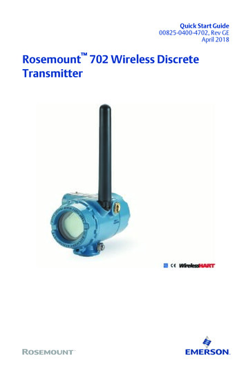
Quick Start Guide00825-0400-4702, Rev GEApril 2018Rosemount 702 Wireless DiscreteTransmitter
Quick Start GuideApril 2018About this guideThis manual supplement provides information on installing, operating, and maintaining theRosemount 702 Wireless Discrete Transmitter for plunger arrival detection. The table below liststhe variants of the Rosemount 702 transmitter; refer to the table if looking for documentation onvariants. Refer to the Rosemount 702 Reference Manual for more instruction. This guide and themanual are available electronically on l702DX22/32/42Two channel discrete I/ORosemount 702 Wireless Discrete Transmitter Refer‐ence Manual702DX61One channel for Tyco TraceTekliquid hydrocarbon leak detectionRosemount 702 Wireless Discrete Transmitter Refer‐ence Manual702DX52Discrete Transmitter for Plunger Arrival DetectionRosemount 702 Wireless Desicrete TransmitterReference Manual SupplementProduct descriptionThe Roseount 702 for plunger arrival detection is designe dto work with the ETC Cyclops plungerarrival sensor (ET-11000). The transmitter provides power to the plunger arrival sensor, reads andcommunication the sensor state via wirelessHART. Features of the Rosemount 702 Transmitterinclude:2 Simple and easy installations proctices currently being used for robust installations Flexibility to meet your most demanding applications Sensor state latching for host system compatibility Provides poiwer to external plunger arrival sensor The integral LCD display conveniently displays the latched plunger sensor state,power output state, and diagnostics of the transmitterRosemount 702 Wireless Discrete Transmitter
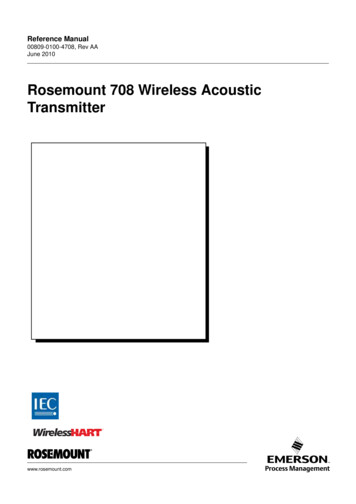
Quick Start GuideApril 2018Figure A-: Rosemount 702 Transmitter for Plunger ArrivalAPlunger Arrival Sensor (ETC Cyclops)GLower Lubricator OutletB702 Plunger ArrivalHWell CasingCLubricatorIProduction gasDPlungerJWell casing/production tubeEWastewaterKWell casingFUpper Lubricator OutletContentsWireless considerations . 4Verify operation .16Physical installation . 7Reference information: wiring switch inputs,output circuits, and leak sensors . 20Device network configuration .14Safety shower and eye washmonitoring . 39Product Certifications . 423Rosemount 702 Wireless Discrete Transmitter
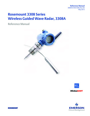
Quick Start GuideApril 20181Wireless considerations1.1Power up sequenceThe Smart Wireless Gateway should be installed and functioning properlybefore any wireless field devices are powered. Install the Black Power Module,SmartPower Solutions model number 701PBKKF (part number00753-9220-0001) into the Rosemount 702 Transmitter to power thedevice. Wireless devices should be powered up in order of proximity from theGateway, beginning with the closest device, then working outward from theGateway. This results in a simpler and faster network installation. EnableActive Advertising on the Gateway to ensure new devices are able to join thenetwork faster. For more information see the Emerson Wireless 1420Gateway Reference Manual.1.2Antenna positionThe antenna should be positioned vertically, either straight up or straightdown, and it should be approximately 3 ft. (1 m) from any large structure,building, or conductive surface to allow for clear communication to otherdevices.Figure 1-1: Antenna Position4Rosemount 702 Wireless Discrete Transmitter
April 20181.3Quick Start GuideConduit entryUpon installation, ensure each conduit entry is either sealed with a conduitplug using approved thread sealant, or has an installed conduit fitting orcable gland with appropriate threaded sealant. Note the conduit entries onthe Rosemount 702 Transmitter are threaded ½–14 NPT.Figure 1-2: Conduit Entry A. Conduit entry1.4Field Communicator connectionsThe power module needs to be installed before the Field Communicator caninterface with the Rosemount 702 Transmitter. This transmitter uses theBlack Power Module; Order model number 701PBKKF or part number00753-9220-0001.Quick Start Guide5
Quick Start GuideApril 2018Figure 1-3: Connection DiagramCH Input Mode:Dry Contact OnlyCH1 CH Output Mode:26VDC Max100mA MaxCMN2P/N 00753-9200-0020N CM2CH134COMMThe Rosemount 702 Transmitter and all other wireless devices should not beset up until after the Smart Wireless Gateway has been installed and isfunctioning properly.6Rosemount 702 Wireless Discrete Transmitter
April 20182Quick Start GuidePhysical installationThe Rosemount 702 Transmitter can be installed in one of twoconfigurations: Direct mount, where the switch is connected directly to the Rosemount702 Transmitter housing’s conduit entry. Remote mount, where the switch is mounted separate from theRosemount 702 Transmitter housing, then connected to the Rosemount702 Transmitter via conduit.Select the installation sequence that corresponds to the mountingconfiguration.2.1Direct mountNoteDirect mount installation should not be employed when using tubing andconnectors such as Swagelok fittings.Figure 2-1: Direct MountA. Rosemount 702 TransmitterB. Float switchQuick Start Guide7
Quick Start GuideApril 2018Procedure1. Install the switch according to standard installation practices making sureto use thread sealant on all connections.2. Attach the Rosemount 702 Transmitter housing to the switch using thethreaded conduit entry.3. Attach the switch wiring to the terminals as indicated on the wiringdiagram (see Chapter 5).4. Connect the Black Power Module.NoteWireless devices should be powered up in order of proximity from theSmart Wireless Gateway, beginning with the closest device to theGateway. This will result in a simpler and faster network installation.5. Close the housing cover and tighten to safety specification. Alwaysensure a proper seal so the metal touches metal, but do not over tighten.6. Position antenna vertically, either straight up or straight down. Theantenna should be approximately 3 ft. (0.91 m) from any large structuresor buildings, to allow clear communication to other devices.8Rosemount 702 Wireless Discrete Transmitter
April 20182.2Quick Start GuideRemote mountFigure 2-2: Remote MountA. Rosemount 702 TransmitterB. Float switchProcedure1. Install the switch according to standard installation practices making sureto use thread sealant on all connections.2. Run wiring (and conduit if necessary) from the switch to the Rosemount702 Transmitter.3. Pull the wiring through the threaded conduit entry of the Rosemount 702Transmitter.4. Attach the switch wiring to the terminals as indicated on the wiringdiagram (see Chapter 5).5. Connect the black power module.Quick Start Guide9
Quick Start GuideApril 2018NoteWireless devices should be powered up in order of proximity from theSmart Wireless Gateway, beginning with the closest device to thegateway. This will result in a simpler and faster network installation.6. Close the housing cover and tighten to safety specification. Alwaysensure a proper seal so the metal touches metal, but do not over tighten.7. Position antenna vertically, either straight up or straight down. Theantenna should be approximately 3 ft. (0.91 m) from any large structuresor buildings, to allow clear communication to other devices.2.3High gain, remote antenna (optional)The high gain, remote antenna options provide flexibility for mounting theRosemount 702 Transmitter based on wireless connectivity, lightningprotection, and current work practices.10Rosemount 702 Wireless Discrete Transmitter
April 2018Quick Start GuideFigure 2-3: Rosemount 702 Transmitter with High Gain, RemoteAntenna2.3.1Install the high gain, remote antenna (WN option)PrerequisitesFind a location where the remote antenna has optimal wireless performance.Ideally this will be 15–25 ft. (4.6–7.6 m) above the ground or 6 ft. (2 m)above obstructions or major infrastructure.Quick Start Guide11
Quick Start GuideApril 2018WARNING!When installing remote mount antennas for the Rosemount 702 Transmitter,always use established safety procedures to avoid falling or contact withhigh-power electrical lines.Install remote antenna components for the Rosemount 702 Transmitter incompliance with local and national electrical codes and use best practices forlightning protection.Before installing, consult with the local area electrical inspector, electricalofficer, and work area supervisor.The Rosemount 702 Transmitter remote antenna option is specificallyengineered to provide installation flexibility while optimizing wirelessperformance and local spectrum approvals. To maintain wirelessperformance and avoid non-compliance with spectrum regulations, do notchange the length of cable or the antenna type.If the supplied remote mount antenna kit is not installed per theseinstructions, Emerson is not responsible for wireless performance or noncompliance with spectrum regulations.Procedure1. Mount the antenna on a 1.5 to 2-in. pipe mast using the suppliedmounting equipment.2. Connect the lightning arrestor directly to the top of the Rosemount 702Transmitter.3. Install the grounding lug, lock washer, and nut on top of lightningarrestor.4. Connect the antenna to the lightning arrestor using the suppliedLMR-400 coaxial cable ensuring the drip loop is not closer than 1 ft. (0.3m) from the lightning arrestor.5. Use the coaxial sealant to seal each connection between the wireless fielddevice, lightning arrestor, cable, and antenna.NoteThe remote mount antenna kit includes coaxial sealant forweatherproofing the cable connections for the lightning arrestor,antenna, and Rosemount 702 Transmitter. Coaxial sealant must beapplied to guarantee performance of the wireless field network. SeeFigure 2‐4 for details on how to apply coaxial sealant.12Rosemount 702 Wireless Discrete Transmitter
April 2018Quick Start GuideFigure 2-4: Applying Coaxial Sealant to Cable Connections6. Ensure the mounting mast and lightning arrestor are grounded accordingto local/national electrical code.Any spare lengths of coaxial cable should be placed in 12-in. (0.3 m) coils.Quick Start Guide13
Quick Start Guide3April 2018Device network configurationIn order to communicate with the Smart Wireless Gateway, and ultimatelythe host system, the transmitter must be configured to communicate withthe wireless network. This step is the wireless equivalent of connecting wiresfrom a transmitter to the information system. Using a Field Communicator orAMS Wireless Configurator, enter the Network ID and Join Key so they matchthe Network ID and Join Key of the Gateway and other devices in thenetwork. If the Network ID and Join Key do not match that of the Gateway,the Rosemount 702 Transmitter will not communicate with the network. TheNetwork ID and Join Key may be obtained from the Smart Wireless Gatewayon the Setup Network Settings page on the web interface, shown inFigure 3‐1.Figure 3-1: Gateway Network Settings3.1AMS Wireless Configurator1. Right click on the Rosemount 702 Transmitter.2. Select Configure.3. When the menu opens, select Join Device to Network.4. Follow the method to enter the Network ID and Join Key.14Rosemount 702 Wireless Discrete Transmitter
April 20183.2Quick Start GuideField CommunicatorThe Network ID and Join Key may be changed in the wireless device by usingthe following Fast Key sequence. Set both Network ID and Join Key.FunctionFast Key sequenceMenu itemsWireless setup2,2,1Network ID, Join Device to NetworkQuick Start Guide15
Quick Start Guide4April 2018Verify operationThere are four ways to verify operation: using the optional local display (LCD),using the Field Communicator, using the Smart Wireless Gateway’sintegrated web interface, or by using AMS Suite Wireless Configurator. If theRosemount 702 Transmitter was configured with the Network ID and JoinKey, and sufficient time has passed, the transmitter will be connected to thenetwork.4.1Local display4.1.1Start-up sequenceWhen the Rosemount 702 Transmitter is first powered up, the LCD displaywill display a sequence of screens: All Segments On, Device Identification,Device Tag, and then the user chosen variables of the periodic display.During steady state operation, the LCD display gives a periodic display of userchosen variables at the configured wireless update rate. These variables canbe selected from a list of six: Channel 1 State Channel 1 Count Channel 2 State Channel 2 Count Electronics Temperature Supply VoltageRefer to the Rosemount 702 Reference Manual for error codes and other LCDdisplay messages. The chevron-shaped status bar at the top of the screenindicates the progress of the network join process. When the status bar isfilled, the device is successfully connected to the wireless network.Searching for network16Joining networkConnected with GNEGOTLIM-OPOKRosemount 702 Wireless Discrete Transmitter
April 20184.2Quick Start GuideField CommunicatorFor HART Wireless transmitter communication, a Rosemount 702Transmitter DD is required.To obtain the latest DD, visit the Emerson EasyUpgrade site at: Emerson.com/Device‐Install‐Kits.4.3FunctionKey sequenceMenu itemsCommunications3, 3Join Status, Wireless Mode, Join Mode, Number of AvailableNeighbors, Number of Advertisements Heard, Number ofJoin AttemptsSmart Wireless GatewayIn the Gateway’s integrated web server, navigate to the Explorer page. Thispage shows whether the device has joined the network and iscommunicating properly.NoteIt may take several minutes for the device to join the network.NoteIf the device joins the network and immediately has an alarm present, it islikely caused by the sensor configuration. Check the sensor wiring (seeFigure 5‐1) and the sensor configuration (see Table 5‐6).Quick Start Guide17
Quick Start GuideApril 2018Figure 4-1: Smart Wireless Gateway Explorer Page4.4AMS Wireless ConfiguratorWhen the device has joined the network, it will appear in AMS WirelessConfigurator as illustrated below.Figure 4-2: AMS Wireless Configurator, Device Explorer Screen18Rosemount 702 Wireless Discrete Transmitter
April 20184.5Quick Start GuideTroubleshootingIf the device is not joined to the network after power up, verify the correctconfiguration of the Network ID and Join Key, and that Active Advertising hasbeen enabled on the Smart Wireless Gateway. The Network ID and Join Key inthe device must match the Network ID and Join Key of the Gateway.Procedure1. From the Gateway's integrated web interface, select Setup NetworkSettings to obtain the Network ID and Join Key (see Figure 4‐3).Figure 4-3: Gateway Network Settings2. To change the Network ID and Join Key in the wireless device, use a FieldCommunicator and enter the following Fast Key sequence.FunctionFast Key sequenceMenu itemsWireless2, 1, 1Join Device to Network3. Follow the on screen prompts.Quick Start Guide19
Quick Start GuideApril 20185Reference information: wiring switch inputs,output circuits, and leak sensors5.1Dry contact switch inputsThe Rosemount 702 Transmitter has a pair of screw terminals for each of twochannels, and a pair of communication terminals. These terminals are labeledas follows:CH1 :Channel one positiveCMN:CommonCH2 :Channel two positiveCMN:CommonCOMM:CommunicationFigure 5-1: Rosemount 702 Transmitter Terminal5.2Wireless output specifications5.2.1Dual inputThe Rosemount 702 Transmitter will accept the input from one or two singlepole single throw switches on inputs CH1 and CH2. The wireless output ofthe transmitter will be both a primary variable (PV) and a secondary variable20Rosemount 702 Wireless Discrete Transmitter
April 2018Quick Start Guide(SV). The PV is determined by the CH1 input. The SV is determined by theCH2 input. A closed switch drives a TRUE output. An Open switch drives aFALSE output.NoteAny dry contact input may optionally be inverted by the device, so changethe discrete logic state. This is useful, for instance, if a normally open switchis used to replace a normally closed switch.Figure 5-2: Single and Dual InputA. Single InputB. Dual InputTable 5-1: Single or Dual Input5.2.2Switch inputWireless outputSwitch inputWireless outputCH1PVCH2SVClosedTRUE (1.0)ClosedTRUE (1.0)OpenFALSE (0.0)OpenFALSE (0.0)Dual input, limit contact logicWhen configured for Limit Contact Logic, the Rosemount 702 Transmitterwill accept the input from two single pole single throw switch on inputs CH1and CH2, and will use limit contact logic for the determination of the wirelessoutputs.Quick Start Guide21
Quick Start GuideApril 2018Figure 5-3: Dual Input, Limit ContactsA. TRUEB. FALSETable 5-2: Dual Input, Limit Contact LogicSwitch input5.2.3Wireless outputCH1CH2PVSVOpenOpenTRAVEL (0.5)TRAVEL (0.5)OpenClosedFALSE (0.0)FALSE (0.0)ClosedOpenTRUE (1.0)TRUE (1.0)ClosedClosedFAULT(NaN)FAULT(NaN)Dual input, opposing contact logicWhen configured for Opposing Contact Logic, the Rosemount 702Transmitter will accept the input from a double pole single throw switch oninputs CH1 and CH2, and will use opposing contact logic for thedetermination of the wireless outputs.22Rosemount 702 Wireless Discrete Transmitter
April 2018Quick Start GuideFigure 5-4: Dual Input, Opposing ContactA. TRUEB. FALSETable 5-3: Dual input, Opposing Contact LogicSwitch inputs5.3Wireless losedFALSE (0.0)FALSE (0.0)ClosedOpenTRUE (1.0)TRUE (1.0)ClosedClosedFAULT(NaN)FAULT(NaN)Momentary discrete inputs, measurement option code 32and 42The Rosemount 702 Transmitter is capable of detecting momentary discreteinputs of 10 milliseconds or more in duration, regardless of the wirelessupdate rate. At each wireless update, the device reports current discreteinput state along with an accumulating count of close-open cycles for eachinput channel.Quick Start Guide23
Quick Start GuideApril 2018Figure 5-5: Momentary Inputs and Accumulating CountA.B.C.D.E.F.Input Switch StateClosedOpenStateCountWireless UpdatesFigure 5-6: Reporting of Current Discrete State and Count in AMS DeviceManagerA. Current StateB. Count24Rosemount 702 Wireless Discrete Transmitter
April 20185.3.1Quick Start GuideSetting variable reportingThe Rosemount 702 Transmitter has two choices for variable reporting:Classic - Discrete State Only, or Enhanced – Discrete State and Count.1. In AMS Device Manager, select Configure Manual Setup HART.2. Set Variable Reporting as desired.OptionDescriptionClassic - Discrete StateOnlyThe Rosemount 702 Transmitter will report variables exactly likethe previous version of the device (measurement option code22).Enhanced – DiscreteState with CountThe Rosemount 702 Transmitter will provide both current stateof the discrete channels, and a count of the discrete statechange cycles.Table 5‐4 shows the variable mapping for both cases.Table 5-4: Variable Mapping5.4Variable reportingPVSVTVQVClassic – Discrete State OnlyCH1 StateCH2 StateElectronics temperatureSupply voltageEnhanced – Discrete Statewith CountCH1 StateCH2 StateCH1 CountCH2 CountDiscrete output circuits, measurement option code 42The Rosemount 702 Transmitter has two channels that can each beconfigured for discrete input or output. Inputs must be dry contact switchinputs and these were described in a preceding section of this document.Outputs are a simple switch closure to activate an output circuit. TheRosemount 702 Transmitter output does not provide any voltage or current,the output circuit must have power of its own. The Rosemount 702Transmitter output has maximum switch capacity per channel of 26 volts DCand 100 milliamps.NoteIt is very important that the polarity of the output circuit is as shown in thewiring diagrams, with the positive ( ) side of the circuit wired to the terminal of each channel, and the negative (-) side of the circuit wired to theCMN terminal. If the output
the wireless network. This step is the wireless equivalent of connecting wires from a transmitter to the information system. Using a Field Communicator or AMS Wireless Configurator, enter the Network ID and Join Key so they match the Network ID and


![Tier 1 Chiropractic Directory [as of April 2018]](/img/8/chiropractic-tier1.jpg)