Transcription
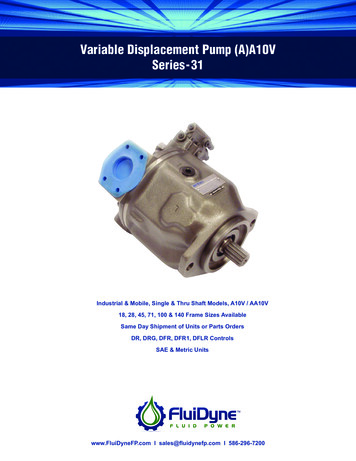
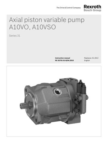
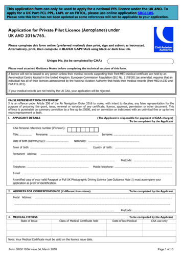
Axial piston variable pumpA10V(S)O Series 31RE-A 92701Edition: 02.2017AmericasReplaces: 03.2012 Size 18 (A10VSO) Sizes 28 to 140 (A10VO) Nominal pressure 4100 psi (280 bar) Maximum pressure 5100 psi (350 bar) Open circuitFeaturesContents Variable pump with axial piston rotary group in swash-Type code2Hydraulic fluids4Working pressure range6Technical data, standard unit7plate design for hydrostatic drives in open circuit. The flow is proportional to the drive speed anddisplacement. The flow can be infinitely varied by adjusting the swashplate angle.Technical data, high-speed version8DG – Two-point control, direct operated12 2 drain portsDR – Pressure controller13 Excellent suction performanceDRG – Pressure controller, remote controlled14 Low noise levelDFR / DFR1 / DRSC – Pressure and flow controller15 Long service lifeDFLR – Pressure, flow and power control17 Favorable power/weight ratioED – Electro-hydraulic pressure control18 Versatile controller rangeER – Electro-hydraulic pressure control19 Short control timeDimensions, size 1820 The through drive is suitable for adding gear pumps and Dimensions, size 2823axial piston pumps up to the same size, i.e., 100%Dimensions, size 4527through drive.Dimensions sizes 71 and 8831Dimensions, size 10035Dimensions, size 14039Dimensions, through drive44Overview of mounting options48Combination pumps A10VO A10VO49Connector for solenoids50Electronic controls50Installation instructions51Project planning notes54Safety instructions55RE-A 92701/02.2017, Bosch Rexroth AG
A10V(S)O Series 31 Axial piston variable pumpType code2Type 213V1828457188Standard version (without code) 100 140 High-speed version (external dimensions are the same as the standard version)–– – H ––––––A10VS– A10VAxial piston unit02Swashplate design, variable, nominal pressure 4100 psi (280 bar),maximum pressure 5100 psi (350 bar)Operating mode03OPump, open circuitSize (NG)041828457188Two-point control, direct operated Pressure controller DRX-T open DFRX-T plugged with flushing function DFR1X-T plugged without flushing function DRSC EF1)Geometric displacement, see table of values on pages 7 and 8100 140Control device05with flow controllerhydraulichydraulicwith flow and differential pressure control, electrically variablewith pressure cut-offhydraulicremote controlledelectricalnegative controlelectricalpositive controlDG DRGU 12 V ED71U 24 V ED72U 12 V ER71U 24 VPressure-flow power control ER72– DFLRSeries0631Series 3, index 1Direction of rotation07Viewed on drive shaftclockwiseRcounter-clockwiseLSealing material08VFKM (fluoroelastomer)Drive shaft09Splined shaftANSI B92.1a1828457188standard shaft 100 140 Ssimilar to shaft “S” however for higher input torque ––Rreduced diameter, limited suitability for through drive(see table of values, page 10) Usame as “U”, higher torque; limited suitability for throughdrive (see table of values, page 10)– W2-hole C4-hole–––––– DMounting flange101)ISO 3019-1 (SAE)See data sheet 92709Bosch Rexroth AG, RE-A 92701/02.2017
Axial piston variable pump A10V(S)O Series 31 3Type code 010203A10V(S)O040506/073108–Working port11SAE flange ports accordingto J518Fastening threadUNF; rearnot for through driveFastening threadUNF; lateral top bottomfor through drive0910111213V1828457188– ––100 140 61––– ––91 –– 62––– ––921828457188 N00 K01Through drive (for mounting options, see page 48)12Flange ISO 3019-1Hub for splined shaft2)DiameterDiameterwithout through drive82-2 (A)5/8 in3/4 in11T 16/32DP K52101-2 (B)7/8 in13T 16/32DP– K681 in15T 16/32DP–– K04127-2 (C)1 1/4 in14T 12/24DP––– K071 1/2 in17T 12/24DP––––– K241 3/4 in13T 8/16DP–––––– K174)Without connector (without solenoid, with hydraulic control only, without code) DEUTSCH - molded connector, 2-pin, without suppressor diode 152-4 (D)9T 16/32DP100 140Connectors for solenoids3)13 Available On requestP– Not availableNotice Note the project planning notes on page 54. In addition to the type code, please specify the relevant technical data when placing your order.2)3)4) Hub for splined shaft according to ANSI B92.1aConnectors for other electric components can deviate.Only with mounting flange DRE-A 92701/02.2017, Bosch Rexroth AG
4A10V(S)O Series 31 Axial piston variable pumpHydraulic fluidsHydraulic fluidsThe A10V(S)O variable pump is designed for operation withNotes on selection of hydraulic fluidHLP mineral oil according to DIN 51524.The hydraulic fluid should be selected such that the operat-Application instructions and requirements for hydraulicing viscosity in the operating temperature range is withinfluids should be taken from the following data sheetsthe optimum range (νopt see selection diagram).before the start of project planning:Notice 90220: Hydraulic fluids based on mineral oils andAt no point of the component may the temperature berelated hydrocarbons 90221: Environmentally acceptable hydraulic fluidshigher than 240 F (115 C). The temperature difference 90222: HFD hydraulic fluids (for permissible technicalspecified in the table is to be taken into account whendetermining the viscosity in the bearing.data, see data sheet 90225)If the above conditions cannot be maintained due toextreme operating parameters, please contact the responsible member of staff at Bosch Rexroth.Viscosity and temperature of hydraulic fluidsCold startViscosityTemperatureCommentνmax 7400 SUS(1600 mm2/s)θSt -40 F (-40 C)t 1 min, without load (p 435 psi (30 bar)), n 1000 rpmΔT 45 F (25 K)between axial piston unit and hydraulic fluidθ -40 F to -13 F(-40 C to -25 C)Note the detailed information on operation with low temperatures, see data sheet 90300-03-BPermissible temperature differenceWarm-up phaseν 7400 to 1850 SUS(1600 to 400 mm2/s)this corresponds, for VG 46 for example, to a temperature rangeof 41 F to 185 F ( 5 C to 85 C) (see selection diagram)Continuous operation ν 1850 to 60 SUS(400 to 10 mm2/s)measured at port L, L1observe the permissible temperature range of the shaft seal(ΔT approx. (9 F) K between the bearing/shaft seal and port L, L1)θ -13 F to 230 F(-25 C to 110 C)Short-term operationνopt 170 to 74 SUS(36 to 16 mm2/s)Range of optimum operating viscosity and efficiencyνmin 50 SUS (7 mm2/s)t 1 min, p 0.3 pnom Selection diagram1004606028040361901702016100821060Minimum permissible viscosity for short-term operation749Optimum operating viscosity range voptOptimum efficiencyMinimum permissible temperature for cold startBosch Rexroth AG, RE-A 92701/02.2017-40-40-13-2514-1032 500 1086122158305070Temperature θ [ C]Viscosity v [mm2/s]930Continuousoperation200Warm-up phase010VG 68VG 46VG 32VG 22[SUS]7400460028001850VG2Maximum permissible viscosity for cold start [mm /s]1600100060040019490239 [ F]115 [ C]
Axial piston variable pump A10V(S)O Series 31 5Hydraulic fluidsFiltration of the hydraulic fluidFiner filtration improves the cleanliness level of the hydraulic fluid, which increases the service life of the axial pistonunit.A cleanliness level of at least 20/18/15 is to be maintainedaccording to ISO 4406.At very high hydraulic fluid temperatures (194 F (90 C) tomaximum 240 F (115 C)), cleanliness level 19/17/14according to at least ISO 4406 is necessary.Please contact us if the above classes cannot be observed. RE-A 92701/02.2017, Bosch Rexroth AG
6A10V(S)O Series 31 Axial piston variable pumpWorking pressure rangeWorking pressure rangePressure at working port BDefinitionNominal pressure pnom4100 psi (280 bar)The nominal pressure corresponds to the maximum design pressure.Maximum pressure pmax5100 psi (350 bar)The maximum pressure corresponds to the maximum working pressure within thesingle operating period. The sum of the single operating periods must not exceedthe total operating period.Single operating period2 msTotal operating period300 hMinimum pressure pB(high-pressure side)absRate of pressure change RA max145 psi (10 bar)1)Minimum pressure on the high-pressure side (B) which is required in order toprevent damage to the axial piston unit.232060 psi/s(16000 bar/s)Maximum permissible speed of pressure build-up and reduction during a pressure change across the entire pressure range.12 psi (0.8 bar)absoluteMinimum pressure at suction port S (inlet) that is required in order to avoid damage to the axial piston unit. The minimum pressure depends on the rotationalspeed and displacement of the axial piston unit.Pressure at suction port S (inlet)Minimum pressurepS minStandard145 psi (10 bar)absolute2)Maximum pressure pS maxLeakage pressure at port L, L1Maximum 7.5 psi (0.5 bar) higher than inlet pressure at port S, but not higherthan pL max. A case drain line to the reservoir is required.30 psi (2 bar)absolute2)Maximum pressure pL max Rate of pressure change RA maxNoticeWorking pressure range valid when using hydraulic fluidspnombased on mineral oils. Please contact us for values forPressure p tother hydraulic fluids.Minimum permissible inlet pressure at suction port S pwith speed increaseIn order to avoid damage to the pump (cavitation), a minimum inlet pressure must be guaranteed at suction port S.The minimum inlet pressure level depends on the rotationalPressure pMaximum pressure pmaxNominal pressure pnomMinimum pressure (high-pressure side)Time tTotal operating period t1 t2 . tn1)2)Lower pressure is time-dependent, please contact usOther values on requestBosch Rexroth AG, RE-A 92701/02.201724 (1.6)20 (1.4)1.117 (1.2)15 (1.0)1.013 (0.9)0.90.70.80.9Standard versiontnHigh speed versiont2Rotational speed n/nnomSingle operating period t112 (0.8)1.0abs1.2Inlet pressure pS Pressure definitionpsi [psi (bar)]speed and the displacement of the variable pump.Time tDisplacement Vg/ Vg maxDuring continuous operation in overspeed over nnom, areduction in operational service life is to be expected dueto cavitation erosion.
Axial piston variable pump A10V(S)O Series 31 7Technical data, standard unit Technical data, standard unitSizeNGDisplacement, geometric, per revolutionVg 0020001800qv maxat nE 1800 rpmqvE maxand Vg maxTorqueΔp 4100 psi (280 bar)at Vg max andRotary stiffnessof drive shaftΔp 1450 psi (100 bar)SPE maxT maxTc8.544.33(45)nmax perm rpmat nE 1800 rpm1402.75at nnom and Vg max(280 bar)100(28)Flowat Δp 4100 psi881.71nnomP max71(18)at Vg maxat nnom, Vg max451.10at Vg Vg max2)and Vg max28inRotational 989350(Nm/rad) (11087)(22317)(37500)(71884)(71884)(121142) (169437)19442302585645756457–Rclb-ft/rad(Nm/rad) ad1231422184389283892867187–(Nm/rad) t/rad1467625419423804238075118122136(Nm/rad) –(19898)(34463)(57460)(57460)(101847) )(0.00093) (0.0017) (0.0033) (0.0083) (0.0083) (0.0167)Moment of inertia for rotary groupMaximum angular ²6800550040002900260024002000Case .4)(0.7)(1.0)(1.6)(1.6)(2.2)(3.0)Weight without through drive (approx.)mlbs28405278781091443)Weight with through drive 8)(55.4)(74.4)More important informations see page 91)2) The values are applicable:‒ At absolute pressure pabs 15 psi (1 bar) at suction port S‒ For the optimal viscosity range of νopt 170 to 80 SUS(36 to 16 mm2/s)‒ For hydraulic fluid based on mineral oilsFor a speed increase up to nmax perm, please observe the diagram onpage 6.3)The data are valid for values between the minimum required andmaximum permissible rotational speed. It applies for externalstimuli (e. g. diesel engine 2 to 8 times rotary frequency, Cardanshaft twice the rotary frequency). The limit value is only valid fora single pump. The load capacity of the connecting parts must beconsidered.RE-A 92701/02.2017, Bosch Rexroth AG
A10V(S)O Series 31 Axial piston variable pumpTechnical data, high-speed version8Technical data, high-speed versionSizeNGDisplacement, geometric, per revolutionVg 140)30002550230020503Rotational speed maximum1)at Vg maxnnomrpmat Vg Vg max2)nmax permrpm3300280025002200Flowat nnom and Vg maxqv erat nnom, Vg max and Δp P 28460(Nm)(200)(316)(445)(623)and Δp 4100 psi (280 bar)Torque at Vg max andΔp 4100 psi (280 bar)Δp 1450 psi (100 bar)Rotary stiffness of driveshaftSRT t20.0780.1070.3960.574(kgm 002000Moment of inertia for rotary groupJTW2)Maximum angular acceleration3)αCase volumeVWeight without through drive (approx.)mWeight with through drive 584122164(kg)(25.1)(38)(55.4)(74.4)More important informations see page 91)2)The values are applicable:‒ At absolute pressure pabs 15 psi (1 bar) at suction port S‒ For the optimal viscosity range of νopt 170 to 80 SUS(36 to 16 mm2/s)‒ For hydraulic fluid based on mineral oilsFor a speed increase up to nmax perm, please observe the diagram onpage 6.Bosch Rexroth AG, RE-A 92701/02.20173)The data are valid for values between the minimum required andmaximum permissible rotational speed. It applies for externalstimuli (e. g. diesel engine 2 to 8 times rotary frequency, Cardanshaft twice the rotary frequency). The limit value is only valid fora single pump. The load capacity of the connecting parts must beconsidered.
Axial piston variable pump A10V(S)O Series 31 9Technical data, high-speed version NoticeDetermining the operating characteristicsFlowTorquePowerqv T P Vg n ηv[gpm (l/min)]231 (1000)Vg Δp[lb-ft (Nm)]24 (20) π ηmh2π T n33000 (60000) qv Δp1714 (600) ηt[HP (kW)] Theoretical values, without efficiency and tolerances;values rounded Operation above the maximum values or below theminimum values may result in a loss of function,a reduced service life or in the destruction of the axialpiston unit. Bosch Rexroth recommends checking theKeyload by means of test or calculation / simulation andVg Displacement per revolution [in3 (cm3)]comparison with the permissible values.Δp Differential pressure [psi (bar)]nRotational speed [rpm]ηvVolumetric efficiencyηhm Hydraulic-mechanical efficiencyηt Total efficiency (ηt ηv ηhm)RE-A 92701/02.2017, Bosch Rexroth AG
A10V(S)O Series 31 Axial piston variable pumpTechnical data, high-speed version10Permissible radial and axial forces of the drive shaftsSizeNGFqMaximum radial force at a/21828457188100140Fq 0)517(2300)629(2800) Fax 00)899(4000)1079(4800)a/2 a/2aMaximum axial forceFax –Notice The values given are maximum values and do not applyto continuous operation.For drives with radial loading (pinion, V-belt drives),please contact us!Permissible input and through-drive (1620)DIAin3/47/811 1/41 1/41 1/21 3/4TE 44)(644)––DIAin3/47/811 1/41 1/4––TE (300)(595)–DIAin5/83/47/8111 1/4–TE )(394)(636)(1220)DIAin–3/47/8111 1/41 1/2STD 2)(492)(778)(1266)RTD 8)(548)––UTD (300)(595)–WTD )(394)(636)(1220)Torque at Vg max and Δp 4100 psi (280 bar)1)T maxMaximum input torque at drive shaft2)SRUWTE maxMaximum through-drive torque1)2)Efficiency not consideredFor drive shafts with no radial forceBosch Rexroth AG, RE-A 92701/02.2017
Axial piston variable pump A10V(S)O Series 31 11Technical data, high-speed version Distribution of torquesT1T2TE1st pump2nd pumpT3TDTorque at 1st pumpT1Torque at 2nd pumpT2Torque at 3rd pumpT3Input torqueThrough-drive torque TE T1 T2 T3TE TE maxTD T2 T3TD TD maxRE-A 92701/02.2017, Bosch Rexroth AG
12A10V(S)O Series 31 Axial piston variable pumpDG – Two-point control, direct operatedDG – Two-point control, direct operatedThe variable pump can be set to a minimum swivel angle by Circuit diagramconnecting an external control pressure to port X.MH1)This will supply control fluid directly to the stroking piston;Xa minimum control pressure of pst 725 psi (50 bar) isrequired.The variable pump can only be switched between Vg maxLBor Vg min.Please note that the required control pressure at port X isdirectly dependent on the actual working pressure pB inport B. (See control pressure characteristic).The maximum permissible control pressure is 280 bar.Control pressure pst in X 0 psi (0 bar)Vg maxControl pressure pst in X 725 psi (50 bar)Vg minRec. control pressure pst [psi (bar)] Control pressure characteristic curve1)L11750 (120)1450 (100)725 (50)0725(50)1450(100)2200(150)2900(200)working pressure pB [psi (bar)]Only size 140Bosch Rexroth AG, RE-A 92701/02.20173600 4100(250) (280)S
Axial piston variable pump A10V(S)O Series 31 13DR – Pressure controller DR – Pressure controllerThe pressure controller limits the maximum pressure at the Circuit diagram, sizes 18 to 100pump outlet within the control range of the variable pump.The variable pump only supplies as much hydraulic fluid asis required by the consumers. If the working pressureexceeds the pressure command value at the pressure valve,the pump will regulate to a smaller displacement to reduceLthe control differential.B Initial position in depressurized state: Vg max. Setting range1) for pressure control steplessly 290 to4100 psi (20 to 280 bar).Standard is 4100 psi (280 bar). Characteristic curveCharacteristic curve valid at n1 1500 rpmand θfluid 120 F (50 C).SHysteresis/pressure rise ΔpmaxL1Working pressure pB [psi (bar)]4100(280) Circuit diagram, size 140Controller data290(20)NGqv minFlow qVqv maxΔp [psi(bar)]Hysteresis andrepeatabilityΔp [psi(bar)]Control fluidconsumption1) 18Pressureincrease[gpm(l/min)]28457160 60 87 115(4) (4) (6) (8)88100130(9)145 175(10) (12)140maximum 45 (3)maximum approx. 0.8 (3)In order to prevent damage to the pump and the system,the permissible setting range must not be exceeded.The range of possible settings at the valve is higher.RE-A 92701/02.2017, Bosch Rexroth AG
14A10V(S)O Series 31 Axial piston variable pumpDRG – Pressure controller, remote controlledDRG – Pressure controller, remote controlledFor the remote controlled pressure controller, the LS pres- Circuit diagram DRG nominal size 18 to 100sure limitation is performed using a separately arranged1pressure relief valve. Therefore any pressure control valueunder the pressure set on the pressure controller can beXregulated. Pressure controller DR see page 13.2A pressure relief valve is externally piped up to port X forremote control. This relief valve is not included in the scopeof delivery of the DRG control.3When there is differential pressure Δp at the control valveand with the standard setting on the remote controlledpressure cut-off of 290 psi (20 bar), the amount of controlLfluid at the port is X approx. 0.4 gpm (1.5 l/min). If a differ-Bent setting (range 145 to 320 psi (10 to 22 bar)) isrequired, please state in plain text.As a separate pressure relief valve (1) we recommend: a direct operated hydraulic or electric proportional one,suitable for the control fluid mentioned above.The max. length of piping should not exceed 6.6 ft (2 m). Basic position in depressurized state:Vg max. Setting range1) for pressure control 290 to 4100 psi(20 to 280 bar) (3).Standard is 4100 psi (280 bar). Setting range for differential pressure 145 to 320 psiL1(10 to 22 bar)(2). Standard is 290 psi (20 bar).SUnloading port X to the reservoir results in a zero stroke(standby) pressure which is approx. 15 to 30 psi(1 to 2 bar) higher than the defined differential pressure p, however system influences are not taken into account.maxHysteresis/repeatability ΔpWorking pressure pB [psi (bar)]4100(280) Circuit diagram, size 14013XNGFlow qVqv maxCharacteristic curve valid at n1 1500 rpmand θfluid 120 F (50 C).2)2 Remote controlled pressure cut-off (G).Controller data DRGStandby2)1)included in the scope of delivery.3 Pressure controller (DR) Characteristic curve DRGqv min1 The separate pressure relief valve and the line are notIn order to prevent damage to the pump and the system,the permissible setting range must not be exceeded.The range of possible settings at the valve is higher.Zero stroke from pressure setting p on controller (2)Bosch Rexroth AG, RE-A 92701/02.2017Hysteresis andrepeatabilityControl fluidconsumptionDR and DRG18Δp [psi(bar)][gpm(l/min)]28457188100maximum 45 (3)maximum approx. 1.2 (4.5)140
Axial piston variable pump A10V(S)O Series 31 15DFR / DFR1 / DRSC – Pressure and flow controller DFR / DFR1 / DRSC – Pressure and flow controller Circuit diagram DFR size 18 to 100In addition to the pressure controller function (seepage 13), a variable orifice (e.g. directional valve) is usedto adjust the differential pressure upstream and down-Plugged with DFR1 / DRSCstream of the orifice. This is used to control the pump flow.The pump flow is equal to the actual hydraulic fluid quantityrequired by the consumer. With all controller combinations,X2the Vg reduction has priority.1 Basic position in depressurized state:Vg max. Setting range1) to 4100 psi (280 bar)3standard is 4100 psi (280 bar). DR pressure controller data see page 13LNoticeB The DFR1 and DRSC versions have no unloading betweenX and the reservoir. Unloading the LS-pilot line must bepossible in the valve system. Because of the flushingfunction of the flow controller in the DRS control valve,sufficient unloading of the X-line must also be provided.If this unloading of the X line does not have to be guaranteed, the DRSC control valve must be used.Hysteresis/pressure rise ΔpWorking pressure pB [psi (bar)]max Characteristic curve4100(280)L1S Circuit diagram, size 140Plugged with DFR1 / DRSCX21Stand by2)0qv minFlow qV3qv maxBFlow qVqV maxqV minn0Rotational speed nCharacteristic curve valid at n1 1500 rpmand θfluid 120 F (50 C). nmaxHysteresis / pressure increase ΔqVmax Characteristic curve at variable rotational speed1 The metering orifice (control block) and the line is notincluded in the scope of delivery.2 Pressure and flow controller (FR).3 Pressure controller (DR)For further information see page 161)2)In order to prevent damage to the pump and the system, thepermissible setting range must not be exceeded.The range of possible settings at the valve is higher.Zero stroke from pressure setting p on controller (2)RE-A 92701/02.2017, Bosch Rexroth AG
A10V(S)O Series 31 Axial piston variable pumpDFR / DFR1 / DRSC – Pressure and flow controller16Differential pressure p: Standard setting: 200 psi (14 bar)If another setting is required, please state in plain text. Setting range: 200 to 320 psi (14 bar to 22 bar)Unloading port X to the reservoir results in azero stroke (standby) pressure which is approx. 15 to 30 psi(1 to 2 bar)higher than the defined differential pressure Δp, however,system influences are not taken into account.Controller dataDR pressure controller data see page 13.Maximum flow deviation measured at drive speedn 1500 rpm.NGFlow deviationΔqV max [gpm (l/min)]Hysteresis and repeatability Δp[psi (bar)]Control fluid consumption[gpm (l/min)]Bosch Rexroth AG, RE-A 0(1.8)0.70(2.8)0.90(3.4)1.10(4.0)1.60(6.0)maximum 60 (4)maximum approx. 0.8 to 1.2 (3 to 4.5) (DFR)maximum approx. 0.8 (3) (DFR1/DRSC)
Axial piston variable pump A10V(S)O Series 31 17DFLR – Pressure, flow and power control DFLR – Pressure, flow and power controlPressure controller equipped like DR(G), see page 13 (14). Circuit diagram, sizes 28 to 100Flow controller equipped like DFR1, see page 15.XIn order to achieve a constant drive torque with varyingworking pressures, the swivel angle and with it the outputflow from the axial piston pump is varied so that the prod-1uct of flow and pressure remains constant.Flow controller is possible below the power control curve.LWorking pressure pB [psi (bar)] Characteristic curve and torque characteristic4350 (300)4100 (280)BMaximumpower curve3600 (250)2900 (200)2200 (150)1450 (100)725 (50)Maximumpower curveSL10 Circuit diagram, size 140X1 qVTorque T [Nm](see table onpage 16)L0Flow qV [%]100Please contact us regarding beginning of controlat 725 psi (50 bar)When ordering please state the power characteristics to beset at the factory in plain text, e.g. 27 HP (20 kW) at1500 rpm.BSL11 The metering orifice (control block) and the line is notincluded in the scope of delivery.Controller data For technical data of pressure controller DR see page 13. For technical data of flow controller FR see page 16. Control fluid consumption approx. 1.5 gpm (5.5 l/min)max. RE-A 92701/02.2017, Bosch Rexroth AG
A10V(S)O Series 31 Axial piston variable pumpED – Electro-hydraulic pressure control18ED – Electro-hydraulic pressure controlThe ED valve is set to a certain pressure by a specifiedvariable solenoid current. Influence of the pressure setting on standby(maximally energized)495 (34)an increase or decrease in the pump swivel angle (flow) in465 (32)order to maintain the electrically set pressure level.435 (30)The pump thus only delivers as much hydraulic fluid as theconsumers can take. The desired pressure level can be setsteplessly by varying the solenoid current.As the solenoid current signal drops towards zero, thepressure will be limited to pmax by an adjustable hydraulicpressure cut-off (secure fail safe function in case of powerfailure, e.g. for fan speed control). The response timecharacteristic curve of the ED control was optimized for theuse as a fan drive system.Standby [psi (bar)]With changes on the consumer (load pressure), this causes405 (28)375 (26)350 (24)320 (22)290 (20)260 (18)230 (16)200 (14)2050 2300 2600 2900 3200 3500 3800 4100(140) (160) (180) (200) (220) (240) (260) (280)Maximum pressure setting [psi (bar)]When ordering, specify the type of application in plain text. Static current-pressure characteristic curve ED(negative characteristic curve measured with pump in zero stroke)Working pressure [psi (bar)]4100(280)XED deactivation ofcontrolMaximum adjustable control pressure2050(140)0 Circuit diagram ED71/ED72Minimum adjustable control pressure0Current I/ImaxL1BHysteresis static 45 psi (3 bar).Maximum working pressure P [psi (bar)](deenergized)Setting range Flow-pressure characteristic curveHysteresis/pressure riseΔp max 60 psi (4 bar)4100(280)2050(140)qv minFlow qVqv maxCharacteristic curves valid at n1 1500 rpm andtfluid 122 F (50 C).Control fluid consumption: 0.8 to 1.2 gpm (3 to 4.5 l/min).For standby standard setting, see diagram on right,other values on request.Bosch Rexroth AG, RE-A 92701/02.2017SL1Technical data, solenoidED71ED72Voltage12 V ( 20%)24 V ( 20%)Start of control at p max0 mA0 mAStart of control at p min1200 mA600 mACurrent limit1.54 A0.77 ANominal resistance (at 68 F (20 C))5.5 Ω22.7 ΩDither frequency100 to200 Hz100 to200 HzDuty cycle100%100%Control currentElectronic controls and type of protection, see page 50Operating temperature range at valve -4 F to 239 F(-20 C to 115 C)
Axial piston variable pump A10V(S)O Series 31 19ER – Electro-hydraulic pressure control ER – Electro-hydraulic pressure controlThe ER valve is set to a certain pressure by a specified Circuit diagramvariable solenoid current. When a change is made at theconsumer (load pressure), the position of the control spoolwill shift.This causes an increase or decrease in the pump swivelangle (flow) in order to maintain the electrically setpressure level.The pump thus only delivers as much hydraulic fluid as theconsumers can take. The desired pressure level can be setLBsteplessly by varying the solenoid current.As the solenoid current signal drops towards zero, thepressure will be limited to pmin (stand by).Working pressure [psi (bar)] Current-pressure characteristic curve(positive characteristic curve measured with pump in zero stroke)4350 (300)4100 (280)3600 (250)2200 (150)SL1Maximumadjustablecontrol pressureTechnical data, solenoidER71ER72Voltage12 V ( 20%)24 V ( 20%)Start of control at p min100 mA50 mAEnd of control at p max1200 mA600 mACurrent limit1.54 A0.77 ANominal resistance (at 68 F (20 C))5.5 Ω22.7 ΩDither frequency100 to200 Hz100 to200 HzDuty cycle100%100%Control currentMinimumadjustableco
Bosch Rexroth AG, RE-A 92701/02.2017 4 A10V(S)O Series 31 Axial piston variable pump Hydraulic fluids Hydraulic fluids The A10V(S)O variable pump is designed for operation with HLP mineral oil according to DIN 51524. Application instructions and requirements for hydraulic fluids should be taken from the following data sheets