Transcription
RE 10 515/07.02Replaces: 05.00Variable vane pumps,pilot operated, type PV7H/A 1790Nominal sizes 14 to 150Series 1XMaximum operating pressure 160 barMaximum flow 270 L/minOverview of contentsPage1233 and 456 to 11121314 to 171819H/A/D 5641/97ContentsFeaturesOrdering details, preferred typesSymbolsFunction, sectionTechnical dataCharacteristic curvesUnit dimensions, single pump with controllerDynamic behaviour of the pressure controlController programme:Symbols, characteristic curves, unit dimensionsLockEngineering guidelines for multiple pumpsCombination possibilities, multiple pumpordering detailsCombination pump - unit dimensionsMotor-pump-drive unit, multiple pumpordering details, E-motor selection tableE-motor technical data and unit dimensionsSpare parts, seal kits, connection flangesEngineering and commissioning guidelinesInstallation guidelinesType PV7/16 C 2021 to 26Type P2V7/ GF1/ 2728293031FeaturesPV7– Variable displacement– Low operating noise– Long bearing life due to hydro-dynamically lubricated plainbearings– Control facility for pressure and flow– Low hysteresis– Very short control times for an and off stroke– Installation and connection dimensions to VDMA 24 560 part 1 ISO 3019/2– Suitable for use with HETG and HEES fluids– The standard PV7 pumps can be combined into numerousvariations of combination pumps– The PV7 pumps can also be combined with internal andexternal gear pumps, axial piston and radial piston pumpsMPU– Is supplied as a completely assembled unit– Drive coupling and pump mounting bracket are not required– Low operating noise due to the compact design 2002by Bosch Rexroth AG, Industrial Hydraulics, D-97813 Lohr am MainAll rights reserved. No part of this document may be reproduced or stored, processed, duplicated or circulated usingelectronic systems, in any form or by any means, without the prior written authorisation of Bosch Rexroth AG.In the event of contravention of the above provisions, the contravening party is obliged to pay compensation.This document was prepared with the greatest of care, and all statements have been examined for correctness.This document is subject to alterations for reason of the continuing further developments of products.No liability can be accepted for any incorrect or incomplete statements.PV71/32RE 10 515/05.00
Ordering detailsBuild and nominal sizesBS 10-NS 14 cm3 10-143BS 10-NS 20 cm 10-20BS 16-NS 20 cm3 16-203BS 16-NS 30 cm 16-303BS 25-NS 30 cm 25-30BS 25-NS 45 cm3 25-453BS 40-NS 45 cm 40-453BS 40-NS 71 cm 40-713BS 63-NS 71 cm 63-71BS 63-NS 94 cm3 63-943BS 100-NS 118 cm 100-1183BS 100-NS 150 cm 100-150PV7–1X /RPipe connection 01 01 01 01 01 01 37 37 07 07 07 07Zero stroke pressure range16 up to 160 bar10 up to 100 bar16 up to 160 bar08 up to 80 bar16 up to 160 bar08 up to 80 bar16 up to 160 bar08 up to 80 bar16 up to 160 bar08 up to 80 bar16 up to 160 bar08 up to 80 barE–SeriesSeries 10 to 19 1X(10 to 19: unchanged installationand connection dimensions)Direction of rotationClockwise RShaft endCylindrical drive shaft with through drive EPipe connectionsStandard versionBS 10, 16, 25:Suction, pressure connection: pipe thread 01BS 40:Suction connection: SAE flange connection,Pressure connection: pipe thread 37BS 63, 100:Suction, pressure connection: SAE flange connection 07C D E N W M K Ordering examples: PV7-1X/16 20RE01MC5-16PV7-1X/40-45RE37KD0-16For pumps with settings to the customer‘s requirements:On the order please state the required setting data in clear text (e.g.qVmax 20 L/min; pzero stroke 70 bar). The pump will be set to therequired values and the operating noise optimised respectively.Directional valve 1)WG Normally closedWH Normally openController option0 Standard3 Lockable5 With K-plate6 With Q-plate7 Lockable with K-plate8 Lockable with Q-plateController typePressure controllerPressure controller for hydraulic remote pressure controlPressure controller with electrical remote pressure control(on request)Flow controllerPressure controller with electrical 2-stage pressure adjustmentSealsNBR sealsFKM shaft seal ring(other seals NBR)Without any clear text information the flow and the zero strokepressure will be set to the relevant maximum values and the operatingnoise will be adjusted accordingly.1)Only for C5, D5 and W controllers (optional)Preferred types (readily MC0-08RD 1010 515/05.00515/07.02REMaterial aterial V7
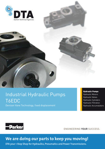
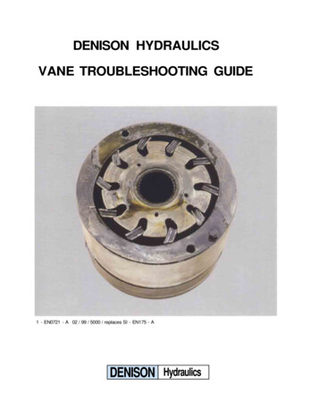
SymbolPPPPS LS LS LS LMSingle pumpDouble pumpMotor-pump-drive unitFunction, sectionDesignThe PV7 hydraulic pumps are variable displacement vane pumps.They mainly consist of the housing (1), rotor (2), vanes (3), stator ring(4), pressure controller (5) and adjustment screw (6).The circular stator ring (4) is retained between the small control piston(10) and the large control piston (11). The third contact point of thering is the height adjustment screw (7).The driven rotor (2) rotates inside the stator ring (4). The vanescontained within the rotor are pressed against the stator ring (4) bycentrifugal force.AdjustmentAt the same time as the system pressure builds up, the rear surfaceof the small control piston (10) is connected to the system via achannel and is, therefore always subjected to the system pressure.When the pump is in its displacement position, the rear surface ofthe large control piston (11) is also subjected to the system pressurevia a drilling in the control piston (14). The control piston (11) withthe larger surface area holds the stator ring (4) in its eccentric position.The pumps displaces fluid at a pressure that is lower than the zerostroke pressure set on the pressure controller (5).The control piston (14) is held in a certain position by a spring (13).X–X19X2961087341112PLSXSuction and displacement processThe chambers (8) which are required for the transport of the fluid areformed by the vanes (3), the rotor (2), the stator ring (4) and thecontrol plates (9).In order to ensure the pump function during commissioning, the statorring (4) is held in the eccentric position (displacement position) bythe spring (12) which is behind the large control piston (11).PV7Due to the rotation of the rotor (2), the chambers (8) increase in sizeand at the same time, fill with fluid via the suction channel (S). Whenthe maximum chamber volume is reached, the chambers (8) aredisconnected from the suction side. As the rotor (2) continues torotate, they are connected to the pressure side and become smallerand press the pressure fluid into the system via the pressure channel(P).3/32RE 10 515/05.00
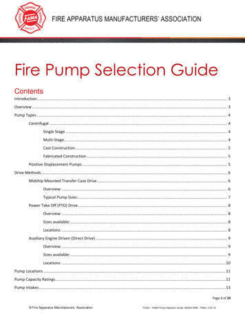
FunctionOff-strokeIf force FP, resulting from the product of pressure x area, exceeds thecounter force FF of the spring, the controller piston (14) is movedagainst the spring (13). In this way, the chamber behind the largecontrol spool (11) is connected to tank and is thus unloaded.The small control piston (10), which is constantly under systempressure, moves the stator ring (4) towards the centre position, virtuallythe zero position. The pump maintains the pressure, the flow decreasesto zero, leakages are compensated for.Power loss and heating of the fluid are kept at a low level.The qV-p-characteristic curve runs vertically and shifts in parallel ashigher pressures are set.FP14513FFPTankSystem pressurePilot pressure104S11FPOn-strokeWhen the pressure in the system falls below the set zerostroke pressure, the spring (13) moves the contol piston(14) back to its inital position.The large control piston (11) is subjected to pressure andmoves the stator ring (4) into the eccentric position. Thepump is in its displacement position.14513FFPTankSystem pressure10RE 10 515/05.004S114/32PV7
Technical data (for applications outside these parameters, please consult us!)ModelPilot operated variable displacement vane pump. adjustableTypePV7Mounting style4-hole flange (to VDMA 24 560 part 1 and ISO 3019/2)Pipe connectionsThreaded or SAE flange connection (dependent on build size)InstallationOptional, preferably horizontal (see page 21)Shaft loadingRadial and axial forces cannot be taken upDirection of rotationClockwise (viewed on the shaft end)nDrive speedmin-1Build size900 to 1800BSNominal sizeDrive power1)Permissible drive torque2)1016kW6.3 5.8 8.5 6.8 13.7 10.2 20.5 16.5 33 20.9 51.5 33TmaxNm30140L/min2.7 1.9– Leakage outlet2090Leakage flow at zero strokeqVL(with operating pressure at outlet pmax)– Outlet100Pmax20213)6314L/minOperating pressure, absolute– Inlet40VgqVMax. flow25cm3293018029 43.5 43.5 6644571barpmaxbar 160 100 160 80 160pmaxbar7128094 118 15044068066 104 108 136 171 2182.5 5.3 3.2 6.5pmin-maxPressure fluidfor use up to 160 bar (nominal pressure)45485.3 117.380 160 80 160800.8 to 2.580 1602HLP mineral oil to DIN 51 524 part 24)Special pressure fluids(only with ordering detail „ K “)– Up to operating pressure pmax 100 barHETG and HEES pressure fluids to VDMA 24 568HLP mineral oil to DIN 51 524 part 2 (from 10 mm2/s)HL mineral oil DIN 51 524 part 1– Up to operating pressure pmax 80 barPressure fluid temperature rangeϑ CViscosity rangeνmm2/sDegree of contaminationmkgChange of flow(with one turn of theadjustment screw and n 1450 min-1)qVL/min2)3)4)16 to 160 at operating temperatureMax. 800 when starting under displacement conditionsMax. 200 when starting under zero stroke conditionsMax. permissible degree of contamination of the pressure fluid isto NAS 1638 class 9. We, therefore recommend a filter with aminimum retention rate of β10 100.Weight (with pressure controller)1)– 10 to 70, take the permitted viscosity range into account!12.51721303756101418253446Measured at n 1450 min-1; p pmax; ν 41 mm2/sThe flow, due to manufacturing tolerances, can exceed thestated values by approx. 6 %(measured at n 1450 min-1; p 10 bar; ν 41 mm2/s).The minimum settable pressure is approx. 20 bar, as standard30 bar is pre-set by the factory.Further special pressure fluids on request (e.g. for systems inthe food processing industry or for fire resistant fluids)!PV75/32RDRE 10 515/07.02515/05.00
Characteristic curves (measured at n 1450 min-1, ν 41 mm2/s and ϑ 50 C)PV7/10-1424Flow in L/min 6165124entcem83P displa2P zero stroke40Drive power in kW 7201020406080100120140160Operating pressure (output) in bar PV7/10-2038732Flow in L/min 245204entcemP displa1631228P zero stroke4001020304050Drive power in kW 628160708090100Operating pressure (output) in bar PV7/10-14PV7/10-206462605856545250484644Noise pressure in dB(A) It is, therefore vital that the required zero stroke pressure is stated onan order when this differs from the nominal pressure.Please take into account the engineering notes on page 30.Noise pressure level in dB(A) Noise pressure level measured in an anechoic chamber toDIN 45 635 part 26. Distance of microphone – pump 1 m.When ordering please take into account!The pump adjustment is so carried out that the most favourable noisepressure level is relation to the largest zero stroke pressure is achieved.tP displacemenkeP zero nP displace02040rokeP zero st6080100120140160Operating pressure (output) in bar Operating pressure (output) in bar n 1450 min-1Drive RPM:n 1000 min-1RE 10 515/05.006/32PV7
Characteristic curves (measured at n 1450 min-1, ν 41 mm2/s and ϑ 50 C)PV7/16-202810248Drive power in kW Flow in L/min 3220616ntmeacelpP dis1284P zero stroke240020406080100120140160Operating pressure (output) in bar PV7/16-30487632Drive power in kW Flow in L/min 4054entcemalP disp241632Pzero stroke810203040506070Operating pressure (output) in bar 80Noise pressure level measured in an anechoic chamber toDIN 45 635 part 26. Distance of microphone – pump 1 m.When ordering please take into account!The pump adjustment is so carried out that the most favourable noisepressure level in relation to the largest zero stroke pressure is achieved.It is, therefore vital that the required zero stroke pressure is stated onan order when this differs from the nominal pressure.Please take into account the engineering guidelines on page 30.PV7/16-20PV7/16-30Nosie pressure level in dB(A) 10Noise pressure level in dB(A) 064626058P displacement56P zero stroke54525048020406080100120140160646260tmenP displace58rokeP zero st5654525048020406080100120140160Operating pressure (output) in bar Operating pressure (output) in bar n 1450 min-1Drive RPM:n 1000 min-1PV77/32RE 10 515/05.00
Characteristic curves (measured at n 1450 min-1, ν 41 mm2/s and ϑ 50 C)PV7/25-304216361412301082418entcem6P displa12604P zero strokeDrive power in kW Flow in L/min 482020406080100120140160Operating pressure (output) in bar PV7/25-457264Flow in L/min 488406entemlacpsiPd3224416Pzero stroke82Drive power in kW 10560203040506070Operating pressure (output) in bar 80Noise pressure level measured in an anechoic chamber toDIN 45 635 part 26. Distance of microphone – pump 1 m.When order please take into account!The pump adjustment is so carried out that the most favourable noisepressure level in relation to the largest zero stroke pressure is achieved.It is, therefore vital that the required zero stroke pressure is stated onan order when this differs from the nominal pressure.Please take into account the engineering guidelines on page 30.PV7/25-30PV7/25-45Nosie pressure level in dB(A) 10Noise pressure level in dB(A) 064626058P displacement565452okeP zero str5048020406080100120140160646260ntP 0160Operating pressure (output) in bar Operating pressure (output) in bar n 1450 min-1Drive RPM:n 1000 min-1RE 10 515/05.008/32PV7
Characteristic curves (measured at n 1450 min-1, ν 41 mm2/s and ϑ 50 C)80287024Flow in L/min 602050Drive power in kW PV7/40-4516401230entcem8P displa20P zero stroke1040020406080100120140160Operating pressure (output) in bar 1201101009080706050403020100201612entcemalP disp84P zero stroke010203040506070Drive power in kW Flow in L/min PV7/40-7180Noise pressure level measured in an anechoic chamber toDIN 45 635 part 26. Distance of microphone – pump 1 m.When ordering please take into account!The pump adjustment is so carried out that the most favourable noisepressure level in relation to the largest zero stroke pressure is achieved.It is, therefore vital that the required zero stroke pressure is stated onan order when this differs from the nominal pressure.Please take into account the engineering guidelines on page 30.PV7/40-45PV7/40-71Nosie pressure level in dB(A) Noise pressure level in dB(A) Operating pressure (output) in bar 706866P displacement64626058P zero 6866Pzero stroke64626058020406080100120140160Operating pressure (output) in bar Operating pressure (output) in bar n 1450 min-1Drive RPM:n 1000 min-1PV79/32RE 10 515/05.00
Characteristic curves (measured at n 1450 min-1, ν 41 mm2/s and ϑ 50 C)PV7/63-711204030Drive power in kW Flow in L/min 96722048entcemP displa1024P zero stroke0020406080100120140160Operating pressure (output) in bar PV7/63-9415020Drive power in kW Flow in L/min 120169012entcemalP disp608304Pzero stroke001020304050607080Noise pressure level measured in an anechoic chamber toDIN 45 635 part 26. Distance of microphone – pump 1 m.When ordering please take into account!The pump adjustment is so carried out that the most favourable noisepressure level in relation to the largest zero stroke pressure is achieved.It is, therefore vital that the required zero stroke pressure is stated onan order when this differs from the nominal pressure.Please take into account the engineering guidelines on page 30.PV7/63-71PV7/63-94Noise pressure level in dB(A) Noise pressure level in dB(A) Operating pressure (output) in bar 6866P displacement64626058P zero nt6866Pzero stroke64626058020406080100120140160Operating pressure (output) in bar Operating pressure (output) in bar n 1450 min-1Drive RPM:n 1000 min-1RE 10 515/05.0010/32PV7
Characteristic curves (measured at n 1450 min-1, ν 41 mm2/s and ϑ 50 C)PV7/100-11820016050120403080entcemP displa20400P zero stroke02040608010012014010Drive power in kW Flow in L/min 60160Operating pressure (output) in bar 240401803012020ntmeacelpP dis1060Drive power in kW Flow in L/min PV7/100-150P zero stroke001020304050607080Operating pressure (output) in bar PV7/100-118PV7/100-150767472 Pdisplacement706866646260Pzero stroke020406080100120140Schalldruckpegel in dB(A) It is, therefore vital that the required zero stroke pressure is stated onan order when this differs from the nominal pressure.Please take into account the engineering guidelines on page 30.Noise pressure level in dB(A) Noise pressure level measured in an anechoic chamber toDIN 45 635 part 26. Distance of microphone – pump 1 m.When ordering please take into account!The pump adjustment is so carried out that the most favourable noisepressure level in relation to the largest zero stroke pressure is achieved.160767472Pdisplacement70Pzero stroke6866646260020406080100120140160Operating pressure (output) in bar Operating pressure (output) in bar n 1450 min-1Drive RPM:n 1000 min-1PV711/32RE 10 515/05.00
Unit dimensions(Dimensions in mm)Single pump with C-, D- and N-controllerD16 71B11B2B4B617L3L43 D347(L9)L2D1H2H4H1D3 0,2H13H3D4H6Ø D5 h8H7Ø D6H5B5 h9L6L8D7L10L5L7B7B3Pressure port 1)Suction port 2)Leak-oil portFor controller with hydraulic remote controlOrdering detail D and flow controllerOrdering detail N , plug G 1/4, 12 deep5 Flow adjustmentAdjustment guidelines:– Flow decreases when turned in a clockwise direction– and increases when turned in an anti-clockwise direction(see page 5)– The set flow should not be less than 50 % of the maximumvalueL1L2L310193 78.5 2616217 863725229 863440 254,6 86 26.563279 9939100 334 111 124291010121316130134.5140.7157.8163.7191.7B4B5 h9B6B712596131 120137 120161 141.2165 141.2184.5 15.5121150H1H2H3H4H5H6H7D1 1)D2 2)D310117745864372522.5G 1/2G1G 1/410316118.581.568724026.528G 3/4G 1 1/4G 3/825118.591.592804026.528G1G 1 1/240118105.58994452635G163118111.5105100472635SAE 1 1/4“100118123.5126111522643SAE 1 1/2“ SAE 2 1/2“Build sizes 10, 16, 25 and 40Pipe thread „G “ to ISO 228/1Build sizes 63 and 100 flange connection to SAERE 10 515/05.004B3BS1)26 Pressure controllerAdjustment guidelines:– The operating pressure increases when turned in a clockwise direction– and decreases when turned in an anti-clockwise directionNote: The zero stroke pressure changes by approx. 19 barfor 1 turn of the adjustment screw.7 The space required to remove the lock cover (the pressure canonly be adjusted when the lock cover is removed)8 Test point G 1/4, 12 deep1234BSD25 8L12)12/32Ø D6D7 H138020 j6912510025 j611G 3/812510025 j611SAE 1 1/2“G 1/216012532 k614SAE 2“G 1/216012532 k614G 3/420016040 k618D4 0,2 Ø D5 h8Build sizes 10, 16 and 25Pipe thread „G “ to ISO 228/1Build sizes 40, 63 and 100 flange connection to SAEPV7
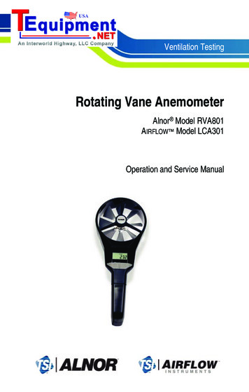
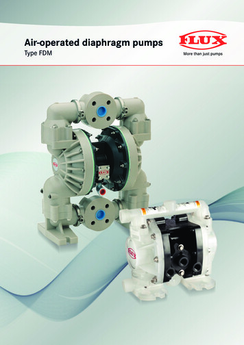
Dynamic charateristics of the pressure controlTest set-up12347001Directional valve (switching time 30 ms)Throttle for adjusting the pressure when the pump is displacingHydraulic pumpPressure measurement point300243Off-strokeqV displacement qV zero stroke10 barOperating pressure p Pressure peakOperating pressure p On-strokeqV zero stroke qV displacementTime t Time t t abt1 on(approx. 90 % flow)t2 onBuild and nominal sizesControl 8014063-71150220 2)––15018080120––10014063-94––200150 2)220150––120150130210100-118200220 180280–Permissible pressure peaksPV7On-stroke in ms (average values)qV zero stroke qV displacement160 130 bar80 60 bar40 30 bart1 ont2 ont1 ont2 ont1 ont2 on10-14100-1501)Off-stroke in ms (average values)qV displacement qV zero stroke20 160 bar20 80 bar20 40 bartoffpmax 1)toffpmaxtoffpmax–2501502)2)Pressure relief valve is required to limit pressure peaks13/32RE 10 515/05.00
Controller programmeC-controllerPressure controllerWith mechanical pressure adjustment, ordering detail C0- (for the lockable version the ordering detail is C3- )SymbolqVPp1LOrdering example:1 Pump: ontrollerPressure controllerWith hydraulic remote pressure adjustment, ordering detail D0- (for the lockable version the ordering detail is D3- )Symbol2qV1PpTRE 10 515/07.02515/05.00LOrdering example:1 Pump: PV7-1X/25-45RE01MD0-082 Optional pressure relief valve; must be orderedseparatelyThe remote control line between the controller andpressure relief valve (2) should not be longer than 2 m.Note: The zero stroke pressure results from the pressureset at the pump and pressure relief valve. The remotecontrol port must not be plugged as the pump will notde-stroke!S14/32PV7
Controller programmeN-controllerFlow controllerWith mechanical flow adjustment, ordering detail N0- (for the lockable version the ordering code is N3- )SymbolqVP231pXTLSE-controller (on request)Pressure controllerWith electrical remote pressure adjustment, ordering detail E0- Symbol2Ordering example:1 Pump: PV7-1X/16-20RE01MN0-16orPV7-1X/63-94RE07MN3-082 Optional orifice (e.g. throttle to RE 27 219)3 Optional pressure relief valve(this valve is necessary as, in this case, there is nocontrol to zero stroke)Items 2 and 3 must be ordered separately.The control lines between the controller connection„X“ and the measurement orifice should not be longerthan 1.5 m.Pressure differential: approx. 13 barqV1PpOrdering example:1 Pump: PV7-1X/16-20RE01ME0-162 Pressure relief valveTLPV7S15/32RE 10 515/05.00515/07.02
Controller programmeW-controllerPressure controllerWith an electrically switchable 2-stage pressure controlOrdering detail W0- Symbol21PTLOrdering example:1 Pump: PV7-1X/16-20RE01MW0-162.1 3/2-way cartridge valve to RE 23 140, optionally normallyopen or normally closed2.2 Pressure relief valve to RE 25 710SqVpUnit dimensions(Dimensions in mm)W-controllerFor further unit dimensions see page 12.Build TSRE 10 515/05.0016/32PV7
Controller programmeHydraulic start-up assistance (K-plate)Sandwich plateWith an unloading valve for start-up at the lowest zero strokepressure.Zero stroke pressure is approx. 20 bar (application dependent)Ordering detail 5- (for the lockable version the ordering detail is 7- )Note: Not suitable for a 2-stage control!Symbol32qVpOrdering example:1 Pump: PV7-1X/40-71RE37MC5-082 3/2-cartridge valve to RE 23 140optionallyNormally closed:Ordering detail: WG orNormally open:Ordering detail: WH or separateShown is type WG3 Optionally C-, D- or N-controller1PLSUnit dimensions(Dimensions in mm)K-plateFor further unit dimensions see page 12.B7H1PBuild RE 10 515/05.00515/07.02
Controller programmeFlow-pressure controller (Q-plate)Sandwich plateFor connecting a flow controller to a pressure compensated pump.Fitted with a standard flow controllerOrdering detail 6- (for the lockable version the ordering detail is 8- )SymbolqVp3Ordering example:1 Pump: PV7-1X/63-712RE07MC6-162 Sandwich plate for connecting the pressurecontroller and flow controller functions3 Flow controller as described on page 144 Pressure controller optionally types C, D, E orW as described on pages 14 and 155 Optional measurement orifice (e.g. throttle toRE 27 219), must be ordered separatelyThe control line between the controller connection„Y“ and the measurement orifice should not belonger than 1.5 m.PY514L2SUnit dimensions(Dimensions in mm)Q-plateFor further unit dimensions see page 12.B2PRE 10 18.5118118118H1Build size1016254063100S18/32PV7
LockMaterial No.: 00844598This lock is fitted to all pumps which have the controller option 3 , 7 or 8 .Functional descriptionAfter unlocking (by turning the key clockwise) the enire lock covercan be removed from the control. The control adjuster is thenaccessible.To lock, the lock cover is placed over the control adjuster and thenpressed home, the lock cylinder is pressed down and the key turnedin an anti-clockwise direction.A lock can be fitted to a standard pump by,– Unscrewing the domed nut from the control adjuster.– Fitting the nut which contains the lock.– Fitting the lock cover as described in the functional description.Engineering guidelines for combination pumps– The PV7 pumps are, as standard, capable of being combined.Each pump is fitted with a splined second shaft end.– When operating the PV7 pump, as a fixed displacement unit,the fixed displacement unit must be the rear pump.– The general technical data is the same as with the single pumps(see page 5).– The pump with the higher load (pressure x flow) should be thefirst pump stage.– When combining several pumps, the torques produced canreach excessively high values.The sum of the torques must not exceed the permissible values(see table)– Combination parts have to be a separate item on an order.– The necessary seals and screws are included in the combinationkit.Single pumpCombination pumpT1TmaxTmaxTabmaxfrommaxPV7Build size1016254063100Max. permissibleDrive torque TmaxOutput torque Tfrom max90140180280440680457090140220340T2Tab1from 11st pumpCombination pump:Required max. pressure:T T12nd pumpTab2from 2P2V7/25-30 V7/25-30 pn 160 bar p V 0.0159(Nm)ηhydr.-mech.T1.2 160 30 0.0159(Nm)0.85T1.2 90 Nm Tfrom maxCalculation exaple:V Displacement in in cm3ηhydr.-mech. Hydraulic-mechanical efficiencyT Torque in Nm p Pressure in barPV7T T1 T2 180 Nm TmaxThe combination pump can be operated on the basis of thecalculated data.19/32RE 10 515/05.00
Combination pump possiblitiesAll of the type PV7 pumps are capable of being combined. Pumpswith an E-shaft have a through drive.Rear pumpPV7-1X/06- RA01M PV7-1X/10- RE01M PV7-1X/16- RE01M PV7-2X/20- RA01M PV7-1X/25- RE01M PV7-1X/40- RE37M PV7-1X/63- RE07M PV7-1X/100- RE07M PGF1-2X/ RH01VU2PGF2-2X/ RJ VU2PGF3-3X/ RJ VU2PGP2-2X/ RJ20VU2PGP3-3X/ RJ VU2PGH2-2X/ RR VU2PGH3-2X/ RR VU2PGH4-2X/ RR VU2PVV/Q1/2-1X/ RJ15 PVV/Q4/5-1X/ RJ15 1PF2G2-4X/ RR20MR1PF1R4-1X/0,40 2,00- WG 1PF1R4-1X/1,60 20,00- RG 1PF1R4-1X/1,60 20,00- RA A10VSO10 UA10VSO18 UA10VO28 SA10VO45 e possible pump combinations, the Material Nos. and the requiredcombination kits are contained within the following table.Front 00544959005449590088062400875983Ordering details for combination pumpsP2 V7 / 100-150 C0 V7 / 100-150 C0 RDouble P2First pumpseriesFirst pump nominal sizeFirst pump controllerSecond pump seriesSecond pump nominal sizeSecond pump controllerE 07 07 E4First pumpmountingflangeSecond pumpconnection portSecond pumpshaft version(if required) 1)First pump connection portFirst pump shaft versionDirection of rotation1) For PGF2 and PGF3Triple and quadruple pumps are coded analogue!RE 10 515/07.02515/05.0020/32PV7
Pump combinations P2V7 V7/ (Dimensions in mm)L6 (L1 L9)L4L1L2L3B1JS9Ø D3D2H1ØØ D1P4 x D4SL51st pump BS 2nd pump 45258242.1247.6266.6254.6267.62
The PV7 hydraulic pumps are variable displacement vane pumps. They mainly consist of the housing (1), rotor (2), vanes (3), stator ring (4), pressure controller (5) and adjustment screw (6). The circular stator ring (4) is retained between the small control piston (10) and the large control piston (11). The third contact point of the