Transcription
2016 AISC StandardsSpecification for Structural Steel Buildings&Code of Standard Practice for Steel Buildingsand BridgesEric BolinStaff EngineerJune 1, 2017
2016 AISC Standards2018 INTERNATIONAL BUILDING CODE2
2016 AISC Standards3
2016 AISC StandardsAISC Committee on Code of Standard Practice Code of Standard Practice for Steel Buildings and Bridges(ANSI/AISC 303-16)AISC Committee on Specifications Specification for Structural Steel Buildings (ANSI/AISC 360-16) Seismic Provisions for Structural Steel Buildings (ANSI/AISC 341-16) Specification for Safety Related Steel Structures for NuclearFacilities (ANSI/AISC N690-17) New standard for Evaluation and Retrofit for Seismic Applications4
2016 AISC Standards: AISC 360-16AISC Committee on SpecificationsTASK COMMITTEESTC 1 – CoordinationTC 7 – Evaluation & RepairTC2 - Editorial/Economy/Efficiency/Practical UseAISI/AISC Fire Committee--Designfor Fire ConditionsTC 3 – Loads, Analysis & StabilityTC 9 – Seismic SystemsTC 4 – Member DesignTC 10 – Materials, Fabrication,Erection & InspectionTC 5 – Composite DesignTC 11 – Nuclear Facilities DesignTC 6 – Connection DesignTC 12 – Quality Certification andQuality Assurance5
2016 AISC Standards: AISC 360-16AISC Committee on SpecificationsMission Statement:Develop the practice-oriented specification for structuralsteel buildings that provides for: Life safety Economical building systems Predictable behavior and response Efficient use6
2016 AISC Standards: AISC 360-16AISC Committee on SpecificationsGoals for 2016 Specification: Implement only essential changesCoordinate with other standardsReflect new researchMore efficient designsBroaden scope or fix omissionsImprove usability/transparencyImprove editorial content7
2016 AISC Standards: AISC 360-162016 Specification for Structural Steel BuildingsChapter A - General ProvisionsChapter B - Design RequirementsChapter C - Design for StabilityChapter D - Design of Members for TensionChapter E - Design of Members for CompressionChapter F - Design of Members for FlexureChapter G - Design of Members for ShearChapter H - Design of Members for Combined Forcesand Torsion8
2016 AISC Standards:AISC 360-162016 Specification for Structural Steel BuildingsChapter I - Design of Composite MembersChapter J - Design of ConnectionsChapter K - Design of HSS and Box Member ConnectionsAdditional Requirements for HSS and BoxSection ConnectionsChapter L - Design for ServiceabilityChapter M - Fabrication and ErectionChapter N - Quality Control and Quality Assurance9
2016 AISC Standards: AISC 360-162016 Specification for Structural Steel BuildingsAppendix 1. Design by Inelastic Advanced AnalysisAppendix 2. Design for PondingAppendix 3. Design for FatigueAppendix 4. Structural Design for Fire ConditionsAppendix 5. Evaluation of Existing StructuresAppendix 6. Member Stability Bracing for Columns and BeamsAppendix 7. Alternative Methods of Design for StabilityAppendix 8. Approximate Second-Order Analysis10
2016 AISC Standards: AISC 360-16Chapter A – General ProvisionsSection A.2 Referenced Specifications, Codes andStandardsUpdated references: ASCE 7 (2016) AWS D1.1 (2015) RCSC Specification (2014) ACI 318 (2014)11
2016 AISC Standards: AISC 360-16Chapter A – General ProvisionsSection A.2 Referenced Specifications, Codes andStandardsNew HSS standards ASTM A1065 and A1085: Round and rectangular HSS shapes with 50 ksiyield strength Design wall thickness Nominal wall thickness12
2016 AISC Standards: AISC 360-16Chapter A – General ProvisionsSection A.2 Referenced Specifications, Codes andStandardsASTM F3125 - New “umbrella” bolt standard Incorporates A325, A325M, A490, A490M, F1825and F2280 Increased bolt pretension values for 1-1/8” diameterand larger A325 bolts. New designation:ASTM A325ASTM F3125 Grade A32513
2016 AISC Standards: AISC 360-16Chapter A – General ProvisionsSection A.2 Referenced Specifications, Codes andStandardsNew “extra” high strength bolts: ASTM F3043: Twist-off “TC” style bolt ASTM F3111: Heavy hex head bolt14
2016 AISC Standards: AISC 360-16Chapter A – General ProvisionsSection A.2 Referenced Specifications, Codes andStandardsNew filler metal standard AWS A5.36: Flux and metal cored electrodes Will supersede AWS A5.20 and A5.2915
2016 AISC Standards:AISC 360-16Chapter B – Design RequirementsSection B3.9 Design for Structural IntegrityProvisions for structural integrity were added for caseswhen required by applicable building code.Included cases: Column splices Beam/girder end connections End connections for members bracing columns16
2016 AISC Standards:AISC 360-16Chapter B – Design RequirementsSection B3.9 Design for Structural IntegrityColumn splices:Tn (D L) for area tributary to column below17
2016 AISC Standards:AISC 360-16Chapter B – Design RequirementsSection B3.9 Design for Structural IntegrityBeam/girder end connections:Tn,min (2/3) Vu 10 kips (LRFD)Tn, min Va 10 kips (ASD)Vu orVaTn18
2016 AISC Standards:AISC 360-16Chapter B – Design RequirementsSection B3.9 Design for Structural IntegrityEnd connections of members bracing columns:Pu or PaTn 0.01(2/3)Pu (LRFD)Tn 0.01Pa (ASD)Tn19
2016 AISC Standards: AISC 360-16Chapter B – Design RequirementsSection B3.10 Design for PondingThe roof system shall be investigated throughstructural analysis to ensure strength and stabilityunder ponding conditions, unless the roof surfaceis provided with a slope of ¼ in. per ft or greatertoward points of free drainage or an adequatesystem of drainage is provided configured toprevent the accumulation of water.20
2016 AISC Standards: AISC 360-16Chapter D – Design of Members forTensionTable D3.1, Revised Shear Lag Factor, UTensile yieldingPn Fy Ag(Eq. D2-1)Tensile rupturePn Fu Ae(Eq. D2-2)Ae AnU(Eq. D3-1)21
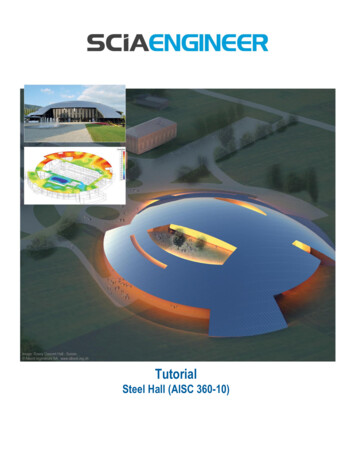
2016 AISC Standards:AISC 360-16Chapter D – Design of Members forTensionTable D3.1, Revised Shear Lag Factor, UCase 4:2010201622
2016 AISC Standards:AISC 360-16Chapter D – Design of Members forTensionTable D3.1, Revised Shear Lag Factor, UCase 4:23
2016 AISC Standards:AISC 360-16Chapter E – Design of Members forCompression Revised effective length term:KL LcSlender element procedure, no longer usesthe Q factors24
2016 AISC Standards:AISC 360-16Chapter E – Design of Members forCompressionSection E7 Members with Slender ElementsFor r2010:Pn Fcr AgFcr based on a Q factor given in Section E72016:Pn FcrAeAe (effective areas of cross-section elementsbased on reduced effective widths, be .)25
2016 AISC Standards:AISC 360-16Chapter E – Design of Members forCompressionSection E7 Members with Slender ElementsMARKETINGEffective Width, bPUBLICATIONS FREDESIGNb For reyr rFcrFyFcr Fel Felb 1 c1 Fcr Fcr 26
2016 AISC Standards:AISC 360-16Section E7 Members with Slender ElementsFor r2 r Fel c2 Fy MARKETINGTable E7.1Effective WidthImperfection Adjustment FactorsPUBLICATIONSc and cSlenderElementccREDESIGN121Stiffened elements except walls of 0.18square and rectangular HSSWalls of square and rectangular 0.20HSSAll other elements0.2221.311.381.4927
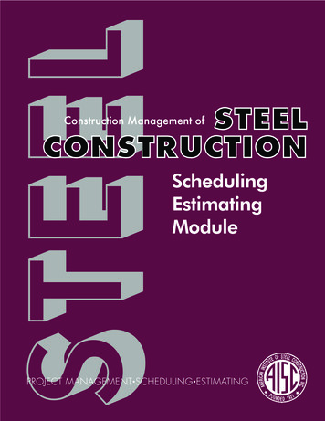
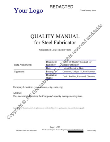
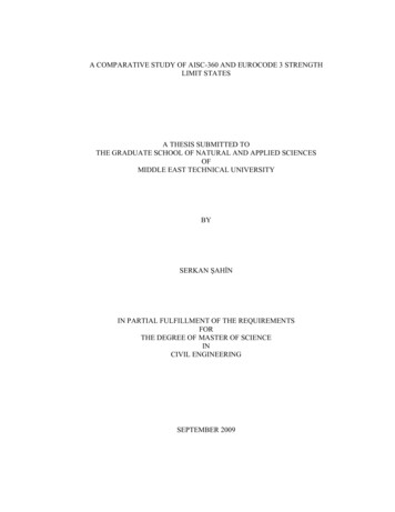
2016 AISC Standards:AISC 360-162016 vs. 2010 Compressive Strength ComparisonWT15x45 (slender stem) - Fy 50 n, kipsw/o Slender Elements2001501005000510152025Effective Length, Lc, (KL)30354028
2016 AISC Standards:AISC 360-16Chapter F – Design of Members for FlexureSection F7 Square and Rectangular HSS and BoxSectionsWeb local buckling - compact webs(1) Compression flange yieldingMn RpgFyS(2) Compression flange local bucklingMn RpgFcrSxcWhere Rpg is the bending strength reduction factordefined in Section F5.229
2016 AISC Standards: AISC 360-16Chapter F – Design of Members for FlexureSection F7 Square and Rectangular HSS and BoxSectionsLateral-torsional buckling Rectangular section bent aboutmajor axis only Typically deflection will control forHSS shapes30
2016 AISC Standards: AISC 360-16Chapter F – Design of Members for FlexureSection F9 Tees and Double Angles Loaded in thePlane of SymmetryStem or angle leg intensionStem or angle leg incompression31
2016 AISC Standards: AISC 360-16Chapter F – Design of Members for FlexureSection F9 Tees and Double Angles Loaded in thePlane of SymmetryFlexural strength, Mn, is the minimum of:1. Yielding—2016 includes case for 2L2. Lateral-torsional buckling (LTB) of tee stems and2L legs—Revised3. Flange local buckling—2016 includes 2L4. Local buckling of tee stems and 2L legs—Revised & 2016 includes 2L32
2016 AISC Standards: AISC 360-16Chapter F – Design of Members for FlexureSection F9 Tees and Double Angles Loaded in thePlane of Symmetry1. Yielding:Mn Mp(a) Tee stems and web legs in tensionMp FyZx 1.6My(F9-2)(b) Tee stems in compressionMp My(F9-4)(c) 2Ls with web legs in compressionMp 1.5My(F9-5)33
2016 AISC Standards: AISC 360-16Chapter F – Design of Members for FlexureSection F9 Tees and Double Angles Loaded in thePlane of SymmetryMARKETINGPUBLICATIONSREDESIGN2. Lateral-Torsional Buckling(a) Stem/legs in tensionFor Lp Lb Lr34
2016 AISC Standards: AISC 360-16Chapter F – Design of Members for FlexureSection F9 Tees and Double Angles Loaded in thePlane of Symmetry2. Lateral-Torsional Buckling(a) Stem/legs in tensionFor Lb Lr:(2016)SameEqn.(2010)35
2016 AISC Standards: AISC 360-16Chapter F – Design of Members for FlexureSection F9 Tees and Double Angles Loaded in thePlane of Symmetry4. Local Buckling—tee stems in flexural compressionMn FcrSxTable B4.1b—Case 14: r (2016) r (2010)36
2016 AISC Standards: AISC 360-16Chapter F – Design of Members for FlexureSection F9 Tees and Double Angles Loaded in thePlane of Symmetry4. Local Buckling—tee stems in flexural compressionMn FcrSxWhen p r(2016)(2010)37
2016 AISC Standards:AISC 360-16Chapter F – Design of Members for FlexureSection F9 Tees and Double Angles Loaded in thePlane of Symmetry4. Local Buckling—tee stems in flexural compressionMn FcrSxWhen r (2016)(2010)38
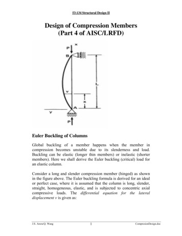
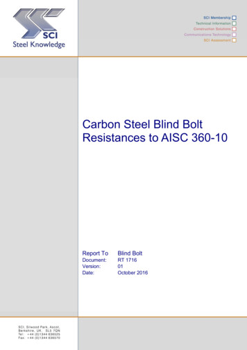
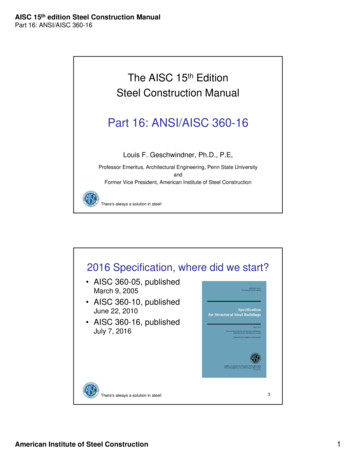
2016 AISC Standards:AISC 360-162016 vs. 2010 ComparisonLocal Buckling—tee stems in flexural compressiond / tw39
2016 AISC Standards: AISC 360-16Chapter G – Design of Members for ShearSection G2.1 I‐Shaped Members without Tension Field Action Increased strength by accounting for some post-bucklingstrength of web Accordingly increased requirements for stiffenersSection G2.1 I‐Shaped Members with Tension Field Action Expanded tension field action beyond the limits found in201040
2016 AISC Standards:AISC 360-16Chapter I – Design of Composite MembersMaterial limitations (Sect. I1.3) Increased maximum reinforcing steel strength to80 ksiConcrete filled axially loaded members Clarifies that longitudinal reinforcement is notrequired (Sect. I2.2a) If longitudinal reinforcement is provided,transverse reinforcement is not required forstrength Updated direct bond interaction provisions(Sect. I6.3c)41
2016 AISC Standards:AISC 360-16Chapter I – Design of Composite MembersStiffness for calculation of req’d strengths (Sect. I1.5) Provides criteria to apply the direct analysis method tocomposite members Research by M.D. Denavit, J.F. Hajjar, T. Perea, andR.T. LeonEffect of ductility at beam/slab interface must be considered(Sect. I3.2d)- see Commentary42
2016 AISC Standards:AISC 360-16Chapter J – Design of ConnectionsSection J1 General ProvisionsBolts in combination with welds at shear connections:2010 – Not permitted except with bolts sharing load withlongitudinally loaded fillet welds. Bolt strength may notexceed 50% of available bearing strength.2016 – Permitted where strain compatibility considered.Bolts must be installed to slip critical and follow otherrequirements of Section J1.8.43
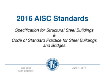
2016 AISC Standards:AISC 360-16Chapter J – Design of ConnectionsSection J3 Bolts and Threaded PartsNew ASTM F3125 bolt standard Group A: A325, A325M, F1852and ASTM A354 Grade BC Group B: A490, A490M, F2280and ASTM A354 Grade BDNew extra high-strength bolts Group C: F3043 and F311144
2016 AISC Standards:AISC 360-16Chapter J – Design of ConnectionsSection J3 Bolts and Threaded Parts64819711845
2016 AISC Standards: AISC 360-16Chapter J – Design of ConnectionsSection J3 Bolts and Threaded PartsChange in minimum bolt hole size (Sect. J3) Standard holes for 1” diameter bolts and largerdh db 1/16” (2010)dh db 1/8”(2016)46
2016 AISC Standards: AISC 360-16Chapter J – Design of ConnectionsSection J3 Bolts and Threaded PartsNew clear distance between bolts in Section J3.3:The distance between centers of standard, oversized orslotted holes shall not be less than 2-2/3 times the nominaldiameter, d, of the fasteners. However, the clear distancebetween bolt holes or slots shall not be less than d.47
2016 AISC Standards: AISC 360-16Chapter J – Design of ConnectionsSection J3 Bolts and Threaded PartsRevised presentation for bolt bearing/tearout2010:Bearing:Rn 1.2lctFu 2.4dtFu2016:(1) Bearing:Rn 1.2lctFu(2) Tearout:Rn 2.4dtFu48
2016 AISC Standards: AISC 360-16Chapter J – Design of ConnectionsSection J10 Flanges and Webs with ConcentratedForcesHSS limit states relocated from Chapter K. The Qf factor added to web crippling and webcompression buckling equations49
2016 AISC StandardsWhat’s NewIn the AISCCode ofStandard Practice for SteelBuildings and Bridges(ANSI/AISC 303-16)50
2016 AISC Standards:AISC 303-16Code of Standard PracticeANSI/AISC 303-16Balanced committee Fabricators - 7 Engineers - 7 Others – 9 General Contractor Code Official Quality Consultant Erector Detailer Architect AttorneyRigorous public review process51
2016 AISC Standards:AISC 303-16Code of Standard Practicefor Steel Buildings and Bridges1. General Provisions2. Classification of Materials3. Design DocumentsDrawings and Specifications4. Approval DocumentsShop and Erection Drawings5. Mater
2016 AISC Standards: AISC 360-16 20 Section B3.10 Design for Ponding The roof system shall be investigated through structural analysis to ensure strength and stability under ponding conditions, unless the roof surface is provided with a slope of ¼ in. per ft or greater toward points of free drainage or an adequate system of drainage is provided configured to prevent the accumulation of water .