Transcription
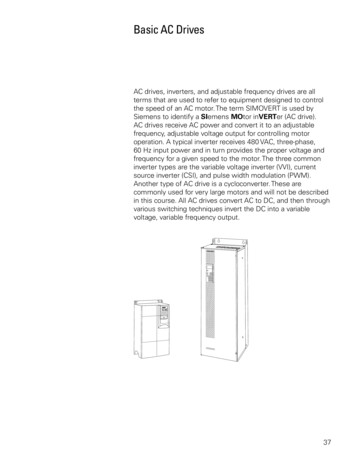
Basic AC DrivesAC drives, inverters, and adjustable frequency drives are allterms that are used to refer to equipment designed to controlthe speed of an AC motor. The term SIMOVERT is used bySiemens to identify a SIemens MOtor inVERTer (AC drive).AC drives receive AC power and convert it to an adjustablefrequency, adjustable voltage output for controlling motoroperation. A typical inverter receives 480 VAC, three-phase,60 Hz input power and in turn provides the proper voltage andfrequency for a given speed to the motor. The three commoninverter types are the variable voltage inverter (VVI), currentsource inverter (CSI), and pulse width modulation (PWM).Another type of AC drive is a cycloconverter. These arecommonly used for very large motors and will not be describedin this course. All AC drives convert AC to DC, and then throughvarious switching techniques invert the DC into a variablevoltage, variable frequency output.37
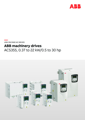
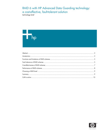
Variable VoltageInverter (VVI)The variable voltage inverter (VVI) uses an SCR converterbridge to convert the incoming AC voltage into DC. The SCRsprovide a means of controlling the value of the rectified DCvoltage from 0 to approximately 600 VDC. The L1 choke andC1 capacitor(s) make up the DC link section and smooththe converted DC voltage. The inverter section consists ofsix switching devices. Various devices can be used such asthyristors, bipolar transistors, MOSFETS, and IGBTs. Thefollowing schematic shows an inverter that utilizes bipolartransistors. Control logic (not shown) uses a microprocessorto switch the transistors on and off providing a variable voltageand frequency to the motor.This type of switching is often referred to as six-step becauseit takes six 60 steps to complete one 360 cycle. Although themotor prefers a smooth sine wave, a six-step output can besatisfactorily used. The main disadvantage is torque pulsationwhich occurs each time a switching device, such as a bipolartransistor, is switched. The pulsations can be noticeable at lowspeeds as speed variations in the motor. These speed variationsare sometimes referred to as cogging. The non-sinusoidalcurrent waveform causes extra heating in the motor requiring amotor derating.38
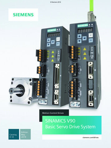
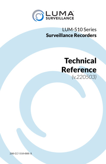
Current Source InverterThe current source inverter (CSI) uses an SCR input to producea variable voltage DC link. The inverter section also uses SCRsfor switching the output to the motor. The current sourceinverter controls the current in the motor. The motor must becarefully matched to the drive.Current spikes, caused by switching, can be seen in the output.At low speeds current pulses can causes the motor to cog.39
Pulse Width ModulationPulse width modulation (PWM) drives, like the SiemensMICROMASTER and MASTERDRIVE VC, provide a moresinusoidal current output to control frequency and voltagesupplied to an AC motor. PWM drives are more efficient andtypically provide higher levels of performance. A basic PWMdrive consists of a converter, DC link, control logic, and aninverter.Converter and DC LinkThe converter section consists of a fixed diode bridge rectifierwhich converts the three-phase power supply to a DC voltage.The L1 choke and C1 capacitor(s) smooth the converted DCvoltage. The rectified DC value is approximately 1.35 times theline-to-line value of the supply voltage. The rectified DC value isapproximately 650 VDC for a 480 VAC supply.40
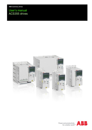
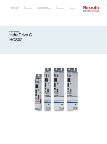
Control Logic and InverterOutput voltage and frequency to the motor are controlled by thecontrol logic and inverter section. The inverter section consistsof six switching devices. Various devices can be used suchas thyristors, bipolar transistors, MOSFETS and IGBTs. Thefollowing schematic shows an inverter that utilizes IGBTs. Thecontrol logic uses a microprocessor to switch the IGBTs on andoff providing a variable voltage and frequency to the motor.IGBTsIGBTs (insulated gate bipolar transistor) provide a highswitching speed necessary for PWM inverter operation. IGBTsare capable of switching on and off several thousand times asecond. An IGBT can turn on in less than 400 nanosecondsand off in approximately 500 nanoseconds. An IGBT consistsof a gate, collector and an emitter. When a positive voltage(typically 15 VDC) is applied to the gate the IGBT will turn on.This is similar to closing a switch. Current will flow betweenthe collector and emitter. An IGBT is turned off by removing thepositive voltage from the gate. During the off state the IGBTgate voltage is normally held at a small negative voltage (-15VDC) to prevent the device from turning on.41
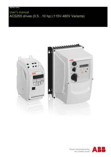
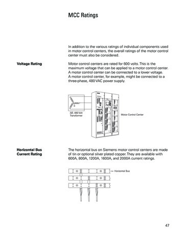
Using Switching Devicesto Develop AC Output42In the following example, one phase of a three-phase output isused to show how an AC voltage can be developed. Switchesreplace the IGBTs. A voltage that alternates between positiveand negative is developed by opening and closing switches ina specific sequence. For example, during steps one and twoA and B- are closed. The output voltage between A and B ispositive. During step three A and B are closed. The differenceof potential from A to B is zero. The output voltage is zero.During step four A- and B are closed. The output voltage fromA to B is negative. The voltage is dependent on the value of theDC voltage and the frequency is dependent on the speed of theswitching. An AC sine wave has been added to the output (A-B)to show how AC is simulated.
PWM OutputThere are several PWM modulation techniques. It is beyondthe scope of this book to describe them all in detail. Thefollowing text and illustrations describe a typical pulse widthmodulation method. An IGBT (or other type switching device)can be switched on connecting the motor to the positive valueof DC voltage (650 VDC from the converter). Current flows inthe motor. The IGBT is switched on for a short period of time,allowing only a small amount of current to build up in the motorand then switched off. The IGBT is switched on and left on forprogressively longer periods of time, allowing current to buildup to higher levels until current in the motor reaches a peak.The IGBT is then switched on for progressively shorter periodsof time, decreasing current build up in the motor. The negativehalf of the sine wave is generated by switching an IGBTconnected to the negative value of the converted DC voltage.43
PWM Voltage and CurrentThe more sinusoidal current output produced by the PWMreduces the torque pulsations, low speed motor cogging, andmotor losses noticeable when using a six-step output.The voltage and frequency is controlled electronically bycircuitry within the AC drive. The fixed DC voltage (650 VDC)is modulated or clipped with this method to provide a variablevoltage and frequency. At low output frequencies a low outputvoltage is required. The switching devices are turned on forshorter periods of time. Voltage and current build up in themotor is low. At high output frequencies a high voltage isrequired. The switching devices are turned on for longer periodsof time, allowing voltage and current to build up to higher levelsin the motor.44
Review 31.The volts per hertz ratio of a 460 volt, 60 Hz motor is.2.An increase in voltage will cause flux (Φ) to, and torque (T) capability to.3.A motor operated within a speed range that allowsa constant volts per hertz ratio is said to be constant.a.horsepowerb.torque4.If torque decreases proportional to speed (RPM)increasing, then is constant.5.Siemens uses the term to identify aSiemens inverter (AC drive).6.On a PWM drive with a 480 VAC supply, theapproximate voltage after being converted to DC isVDC.7.IGBTs are capable of being switched severala second.a.c.8.timesthousand timesb.d.hundred timesmillion timesA PWM output is preferred to a six-step output becausea.b.c.d.PWM provides a more sinusoidal outputCogging is more noticeable on a six-stepThe non-sinusoidal waveform of asix-step increases motor heata, b, and c45
Siemens MICROMASTERSiemens offers a broad range of AC drives. In the past, ACdrives required expert set-up and commissioning to achievedesired operation. The Siemens MICROMASTER offers “out ofthe box” commissioning with auto tuning for motor calibration,flux current control, vector control, and PID (ProportionalIntegral-Derivative) regulator loops. The MICROMASTER iscontrolled by a programmable digital microprocessor and ischaracterized by ease of setup and use.46
FeaturesThe MICROMASTER is suitable for a variety of variable-speedapplications, such as pumps, fans, and conveyor systems. TheMICROMASTER is compact and its range of voltages enablethe MICROMASTER to be used all over the world.MICROMASTER 410The MICROMASTER 410 is available in two frame sizes(AA and AB) and covers the lower end of the performancerange. It has a power rating of 1/6 HP to 1 HP. TheMICROMASTER 410 features a compact design, fanlesscooling, simple connections, an integrated RS485communications interface, and easy startup.47
MICROMASTER 420The MICROMASTER 420 is available in three frame sizes (A,B, and C) with power ratings from 1/6 HP to 15 HP. Among thefeatures of the MICROMASTER 420 are the following: 48Flux Current Control (FCC)Linear V/Hz ControlQuadratic V/Hz ControlFlying RestartSlip CompensationAutomatic RestartPI Feedback for Process ControlProgrammable Acceleration/DecelerationRamp SmoothingFast Current Limit (FCL)Compound Braking
MICROMASTER 440The MICROMASTER 440 is available in six frame sizes(A - F) and offers higher power ranges than the 420, with acorresponding increase in functionality. For example, the 440has three output relays, two analog inputs, and six isolateddigital inputs. The two analog inputs can also be programmedfor use as digital inputs. The 440 also features Sensorless VectorControl, built-in braking chopper, 4-point ramp smoothing, andswitchable parameter sets.49
Design50In order to understand the MICROMASTER’s capabilities andsome of the functions of an AC drive we will look at the 440.It is important to note; however, that some features of theMICROMASTER 440 are not available on the 410 and 420.The MICROMASTER has a modular design that allows theuser configuration flexibility. The optional operator panelsand PROFIBUS module can be user installed. There are sixprogrammable digital inputs, two analog inputs that can alsobe used as additional digital inputs, two programmable analogoutput, and three programmable relay output.
Operator PanelsThere are two operator panels, the Basic Operator Panel (BOP)and Advanced Operator Panel (AOP). Operator panels areused for programming and drive operation (start, stop, jog, andreverse).BOPIndividual parameter settings can be made with the BasicOperator Panel. Parameter values and units are shown on a5-digit display. One BOP can be used for several units.AOPThe Advanced Operator Panel enables parameter sets to beread out or written (upload/download) to the MICROMASTER.Up to ten different parameter sets can be stored in the AOP.The AOP features a multi-line, plain text display. Severallanguage sets are available. One AOP can control up to 31drives.Changing Operator PanelsChanging operator panels is easy. A release button above thepanel allows operator panels to be interchanged, even underpower.51
ParametersA parameter is a variable that is given a constant value.Standard application parameters come preloaded, which aregood for many applications. These parameters can easily bemodified to meet specific needs of an application. Parameterssuch as ramp times, minimum and maximum frequencies, andoperation modes are easily set using either the BOP or AOP.The “P” key toggles the display between a parameter numberand the value of the parameter. The up and down pushbuttonsscroll through parameters and are used to set a parametervalue. In the event of a failure the inverter switches off and afault code appears in the display.Ramp FunctionA feature of AC drives is the ability to increase or decrease thevoltage and frequency to a motor gradually. This accelerates themotor smoothly with less stress on the motor and connectedload. Parameters P002, P003 and P004 are used to set aramp function. Acceleration and deceleration are separatelyprogrammable from 0 to 650 seconds. Acceleration, forexample, could be set for 10 seconds and deceleration could beset for 60 seconds.Smoothing is a feature that can be added to the acceleration/deceleration curve. This feature smooths the transition betweenstarting and finishing a ramp. Minimum and maximum speedare set by parameters P012 and P013.52
Analog InputsThe MICROMASTER 440 has two analog inputs (AIN1 andAIN2), allowing for a PID control loop function. PID control loopsare used in process control to trim the speed. Examples aretemperature and pressure control. Switches S1 and S2 are usedto select a 0 mA to 20 mA or a 0 V to 10 V reference signal. Inaddition, AIN1 and AIN2 can be configured as digital inputs.In the following example AIN1 is set up as an analog referencethat controls the speed of a motor from 0 to 100%. Terminalone (1) is a 10 VDC power supply that is internal to the drive.Terminal two (2) is the return path, or ground, for the 10 Voltsupply. An adjustable resistor is connected between terminalsone and two. Terminal three (3) is the positive ( ) analoginput to the drive. Note that a jumper has been connectedbetween terminals two (2) and four (4). An analog input cannotbe left floating (open). If an analog input will not be used itmust be connected to terminal two (2). The drive can alsobe programmed to accept 0 to 20 mA, or 4 to 20 mA speedreference signal. These signals are typically supplied to the driveby other equipment such as a programmable logic controller(PLC).53
Digital InputsThe MICROMASTER 440 has six digital inputs (DIN1 - DIN6).In addition AIN1 (DIN7) and AIN2 (DIN8) can be configured asdigital inputs. Switches or contacts can be connected betweenthe 24 VDC on terminal 9 and a digital input. Standard factoryprogramming uses DIN1 as a Start/Stop function. DIN 2 is usedfor reverse, while DIN3 is a fault reset terminal. Other functions,such as preset speed and jog, can be programmed as well.ThermistorSome motors have a built in thermistor. If a motor becomesoverheated the thermistor acts to interrupt the power supplyto the motor. A thermistor can be connected to terminals 14and 15. If the motor gets to a preset temperature as measuredby the thermistor, the driver will interrupt power to the motor.The motor will coast to a stop. The display will indicate a faulthas occurred. Virtually any standard thermistor as installed instandard catalog motors will work. Snap-action thermostatswitches will also work.54
Analog OutputsAnalog outputs can be used to monitor output frequency,frequency setpoint, DC-link voltage, motor current, motortorque, and motor RPM. The MICROMASTER 440 has twoanalog outputs (AOUT1 and AOUT2).Relay OutputThere are three programmable relay outputs (RL1, RL2, andRL3) on the MASTERDRIVE 440. Relays can be programmed toindicate various conditions such as the drive is running, a failurehas occurred, converter frequency is at 0 or converter frequencyis at minimum.55
Serial CommunicationThe MICROMASTER 440 has an RS485 serial interface thatallows communication with computers (PCs) or programmablelogic controllers (PLCs). The standard RS485 protocol is calledUSS protocol and is programmable up to 57.6 K baud. SiemensPROFIBUS protocol is also available. It is programmable upto 12 M baud. Contact your Siemens sales representative forinformation on USS and PROFIBUS protocol.Current LimitThe MICROMASTER 440 is capable of delivering up to 150%of drive rated current for 60 seconds within a period of 300seconds or 200% of drive rated current for a period of 3seconds within a period of 60 seconds. Sophisticated speed/time/current dependent overload functions are used to protectthe motor. The monitoring and protection functions includea drive overcurrent fault, a motor overload fault, a calculatedmotor over temperature warning, and a measured motor overtemperature fault (requires a device inside the motor).Low Speed BoostWe learned in a previous lesson that a relationship existsbetween voltage (E), frequency (F), and magnetising flux (Φ).We also learned that torque (T) is dependent on magnetisingflux. An increase in voltage, for example, would cause anincrease in torque.Some applications, such as a conveyor, require more torque tostart and accelerate the load at low speed. Low speed boost isa feature that allows the voltage to be adjusted at low speeds.This will increase/decrease the torque. Low speed boost canbe adjusted high for applications requiring high torque at lowspeeds. Some applications, such as a fan, don’t require asmuch starting torque. Low speed boost can be adjusted low forsmooth, cool, and quiet operation at low speed. An additionalstarting boost is available for applications requiring high startingtorque.56
the speed of an AC motor. The term SIMOVERT is used by Siemens to identify a SIemens MOtor inVERTer (AC drive). AC drives receive AC power and convert it to an adjustable frequency, adjustable voltage output for controlling motor operation. A typical inverter receives 480 VAC, three-phase, 60 Hz input power and in turn provides the proper .