Transcription
Siemens STEP 2000 CourseBasics ofElectricityIt's easy to get in STEP!Download any course.Hint: Make sure you download all parts for each course and the test answer form.Complete each chapter and its review sectionPrint the test answer form, take the final exam and fill in the form.Hint: The final exam is always at the end of the last part.Send your test answer form to EandM for grading. If you achieve a score of 70% or better, we'llsend you a certificate of completion! If you have any questions, contact EandM Training at866.693.2636 or fax 707.473.3190 or training@eandm.com.Need more information? Contact EandM at866.693.2636or fax 707.473.3190or sales@eandm.comfor product information, quotes,classroom training courses and more.STEP 2000 Courses distributed bywww.eandm.com
Table of ContentsIntroduction .2Electron Theory .4Conductors, Insulators and Semiconductors .5Electric Charges .7Current.9Voltage . 11Resistance . 13Simple Electric Circuit . 15Ohm’s Law . 16DC Series Circuit . 18DC Parallel Circuit .23Series-Parallel Circuits .30Power.34Magnetism .37Electromagnetism .39Introduction to AC .42AC Generators .44Frequency .47Voltage and Current .48Inductance .51Capacitance .56Inductive and Capacitive Reactance .61Series R-L-C Circuit .67Parallel R-L-C Circuit .69Power and Power Factor in an AC Circuit . 71Transformers .75Three-Phase Transformers .80Review Answers .83Final Exam .841
IntroductionWelcome to the first course in the STEP series,Siemens Technical Education Program designed to prepareour distributors to sell Siemens Energy & Automation productsmore effectively. This course covers Basics of Electricity and isdesigned to prepare you for subsequent courses on SiemensEnergy & Automation products.Upon completion of Basics of Electricity you will be able to:2 Explain the difference between conductors and insulators Use Ohm’s Law to calculate current, voltage, andresistance Calculate equivalent resistance for series, parallel, orseries-parallel circuits Calculate voltage drop across a resistor Calculate power given other basic values Identify factors that determine the strength and polarity ofa current-carrying coil’s magnetic field Determine peak, instantaneous, and effective values of anAC sine wave Identify factors that effect inductive reactance andcapacitive reactance in an AC circuit Calculate total impedance of an AC circuit Explain the difference between real power and apparentpower in an AC circuit Calculate primary and secondary voltages of single-phaseand three-phase transformers Calculate kVA of a transformer
The objectives listed above may sound strange to you. You mayalso wonder why you would need to know these things to sellSiemens Energy & Automation products. Developing a basicknowledge of electrical concepts, however, will help you tobetter understand customer applications. In addition, you will bebetter able to describe products to customers and determineimportant differences between products.If you are an employee of a Siemens Energy & Automationauthorized distributor, fill out the final exam tear-out card andmail in the card. We will mail you a certificate of completion ifyou score a passing grade. Good luck with your efforts.3
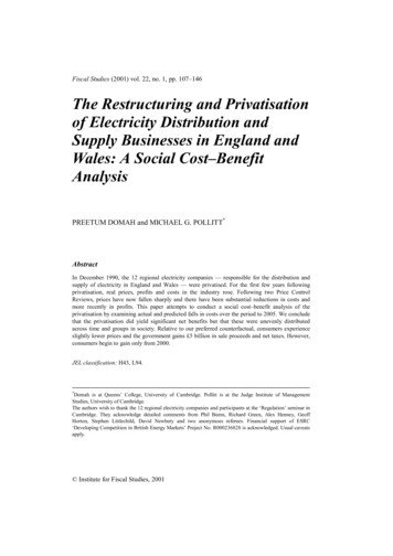
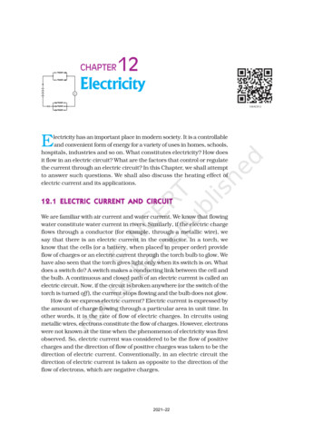
Electron TheoryElements of an AtomAll matter is composed of molecules which are made up of acombination of atoms. Atoms have a nucleus with electronsorbiting around it. The nucleus is composed of protons andneutrons (not shown). Most atoms have an equal number ofelectrons and protons. Electrons have a negative charge (-).Protons have a positive charge ( ). Neutrons are neutral. Thenegative charge of the electrons is balanced by the positivecharge of the protons. Electrons are bound in their orbit bythe attraction of the protons. These are referred to as boundelectrons.ElectronProtonNucleusFree Electrons4Electrons in the outer band can become free of their orbitby the application of some external force such as movementthrough a magnetic field, friction, or chemical action. These arereferred to as free electrons. A free electron leaves a void whichcan be filled by an electron forced out of orbit from anotheratom. As free electrons move from one atom to the next anelectron flow is produced. This is the basis of electricity.
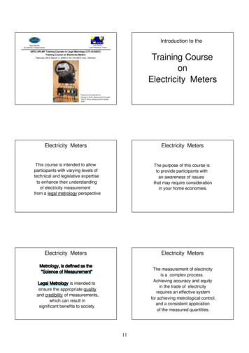
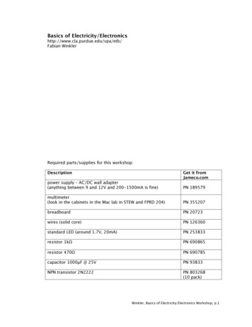
Conductors, Insulators and SemiconductorsConductorsAn electric current is produced when free electrons move fromone atom to the next. Materials that permit many electrons tomove freely are called conductors. Copper, silver, aluminum,zinc, brass, and iron are considered good contors. Copper is themost common maal used for contors and is relatively insive.InsulatorsMaterials that allow few free electrons are called insulators.Materials such as plastic, rubber, glass, mica, and ceramic aregood insulators.An electric cable is one example of how conductors andinsulators are used. Electrons flow along a copper conductor toprovide energy to an electric device such as a radio, lamp, or amotor. An insulator around the outside of the copper conductoris provided to keep electrons in the conductor.Rubber InsulatorCopper Conductor5
SemiconductorsSemiconductor materials, such as silicon, can be usedto manufacture devices that have characteristics of bothconductors and insulators. Many semiconductor devices willact like a conductor when an external force is applied in onedirection. When the external force is applied in the oppositedirection, the semiconductor device will act like an insulator.This principle is the basis for transitors, diodes, and other solidstate electronic devices.TransistorDiodeReview 11.List the three basic elements of an atom and state thecharge of each (positive, negative, or neutral).ElementCharge2.An electron forced out of orbit by an external force iscalled a .3.Conductors allow free electrons to flowwhen an external electric force is applied.4.Which of the following materials are good conductors?a. copperb. plasticc. silverd. r devices can be manufactured to allowelectrons to flow in one direction andelectrons to flow in the opposite direction.
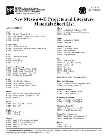
Electric ChargesNeutral State of an AtomElements are often identified by the number of electrons inorbit around the nucleus of the atoms making up the elementand by the number of protons in the nucleus. A hydrogenatom, for example, has only one electron and one proton. Analuminum atom (illustrated) has 13 electrons and 13 protons. Anatom with an equal number of electrons and protons is said tobe electrically neutral.Outer BandPositive andNegative ChargesElectrons in the outer band of an atom are easily displaced bythe application of some external force. Electrons which areforced out of their orbits can result in a lack of electrons wherethey leave and an excess of electrons where they come to rest.The lack of electrons is called a positive charge because thereare more protons than electrons. The excess of electrons has anegative charge. A positive or negative charge is caused by anabsence or excess of electrons. The number of protons remainsconstant.Neutral ChargeNegative ChargePositive Charge7
Attraction and Repulsion ofElectric ChargesThe old saying, “opposites attract,” is true when dealing withelectric charges. Charged bodies have an invisible electricfield around them. When two like-charged bodies are broughttogether, their electric field will work to repel them. When twounlike-charged bodies are brought together, their electric fieldwill work to attract them. The electric field around a chargedbody is represented by invisible lines of force. The invisiblelines of force represent an invisible electrical field that causesthe attraction and repulsion. Lines of force are shown leaving abody with a positive charge and entering a body with a negativecharge.Unlike Charges AttractCoulomb’s Law8Like Charges RepelDuring the 18th century a French scientist, Charles A. Coulomb,studied fields of force that surround charged bodies. Coulombdiscovered that charged bodies attract or repel each otherwith a force that is directly proportional to the product of thecharges, and inversely proportional to the square of the distancebetween them. Today we call this Coulomb’s Law of Charges.Simply put, the force of attraction or repulsion depends onthe strength of the charged bodies, and the distance betweenthem.
CurrentElectricity is the flow of free electrons in a conductor fromone atom to the next atom in the same general direction. Thisflow of electrons is referred to as current and is designatedby the symbol “I”. Electrons move through a conductor atdifferent rates and electric current has different values. Currentis determined by the number of electrons that pass througha cross-section of a conductor in one second. We mustremember that atoms are very small. It takes about1,000,000,000,000,000,000,000,000 atoms to fill one cubiccentimeter of a copper conductor. This number can be simplifiedusing mathematical exponents. Instead of writing 24 zeros afterthe number 1, write 1024. Trying to measure even small valuesof current would result in unimaginably large numbers. For thisreason current is measured in amperes which is abbreviated“amps”. The letter “A” is the symbol for amps. A current of oneamp means that in one second about 6.24 x 10¹⁸ electronsmove through a cross-section of conductor. These numbers aregiven for information only and you do not need to be concernedwith them. It is important, however, that the concept of currentflow be unstood.Units of MeasurementThe following chart reflects special prefixes that are used whendealing with very small or large values of current:PrefixSymbolDecimal1 kiloampere1 milliampere1 microampere1 kA1 mA1 mA1000 A1/1000 A1/1,000,000 A9
Direction of Current FlowSome authorities distinguish between electron flow andcurrent flow. Conventional current flow theory ignores theflow of electrons and states that current flows from positiveto negative. To avoid confusion, this book will use the electronflow concept which states that electrons flow from negative topositive. Electron Flow10 ConventionalCurrent Flow
VoltageElectricity can be compared with water flowing through a pipe.A force is required to get water to flow through a pipe. Thisforce comes from either a water pump or gravity. Voltage is theforce that is applied to a conductor that causes electric currentto flow.Water Flow Through a PipeCurrent Flow Through a ConductorElectrons are negative and are attracted by positive charges.They will always be attracted from a source having an excessof electrons, thus having a negative charge, to a source havinga deficiency of electrons which has a positive charge. The forcerequired to make electicity flow through a conductor is calleda difference in potential, electromotive force (emf), or moresimply referred to as voltage. voltage is designated by the letter“E”, or the letter “V”. The unit of measurement for voltage isvolts which is also designated by the letter “V”.11
Voltage SourcesAn electrical voltage can be generated in various ways. Abattery uses an electrochemical process. A car’s alternator anda power plant generator utilizes a magnetic induction process.All voltage sources share the characteristic of an excess ofelectrons at one terminal and a shortage at the other terminal.This results in a difference of potential between the twoterminals.Shortage of ElectronsExcess of Electrons Batter yVoltage Circuit SymbolThe terminals of a battery are indicated symbolically on anelectrical drawing by two lines. The longer line indicates thepositive terminal. The shorter line indicates the negativeterminal. Units of Measurement12The following chart reflects special prefixes that are used whendealing with very small or large values of voltage:PrefixSymbolDecimal1 kilovolt1 millivolt1 microvolt1 kV1 mV1 mV1000 V1/1000 V1/1,000,000 V
ResistanceA third factor that plays a role in an electrical circuit isresistance. All material impedes the flow of electrical currentto some extent. The amount of resistance depends uponcomposition, length, cross-section and temperature of theresistive material. As a rule of thumb, resistance of a conductorincreases with an increase of length or a decrease of crosssection. Resistance is designated by the symbol “R”. The unit ofmeasurement for resistance is ohms (Ω).Resistance Circuit SymbolsResistance is usually indicated symbolically on an electricaldrawing by one of two ways. An unfilled rectangle is commonlyused. A zigzag line may also be used.Resistance can be in the form of various components. Aresistor may be placed in the circuit, or the circuit might containother devices that have resistance.Units of MeasurementThe following chart reflects special prefixes that are commonlyused when dealing with values of resistance:PrefixSymbolDecimal1 kilohm1 megohm1 kΩ1 MΩ1000 Ω1,000,000 Ω13
Review 21.Elements are identified by the number ofin orbit around the nucleus.2.A material that has an excess of electrons is said tohave a charge.3.A material that has a deficiency of electrons is said tohave a charge.4.Like charges and unlike charges.5.The force that is applied to a conductor to cause currentflow is .6.Electrons move from .a. positive to negativeb. negative to positive7.With an increase of length or a decrease of crosssection of a conductor, resistance will .a. increaseb. decrease14
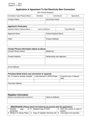
Simple Electric CircuitAn Electric CircuitA fundamental relationship exists between current, voltage, andresistance. A simple electric circuit consists of a voltage source,some type of load, and a conductor to allow electrons to flowbetween the voltage source and the load. In the followingcircuit a battery provides the voltage source, electrical wire isused for the conductor, and a light provides the resistance. Anadditional component has been added to this circuit, a switch.There must be a complete path for current to flow. If the switchis open, the path is incomplete and the light will not illuminate.Closing the switch completes the path, allowing electrons toleave the negative terminal and flow through the light to thepositive terminal. An Electrical CircuitSchematicSwitch The following schematic is a representation of an electricalcircuit, consisting of a battery, a resistor, a voltmeter and anammeter. The ammeter, connected in series with the circuit,will show how much current flows in the circuit. The voltmeter,connected across the voltage source, will show the value ofvoltage supplied from the battery. Before an analysis can bemade of a circuit, we need to understand Ohm’s Law. A VR15
Ohm’s LawGeorge Simon Ohmand Ohm’s LawThe relationship between current, voltage and resistance wasstudied by the 19th century German mathematician, GeorgeSimon Ohm. Ohm formulated a law which states that currentvaries directly with voltage and inversely with resistance. Fromthis law the following formula is derived:I ERor Current VoltageResistanceOhm’s Law is the basic formula used in all electrical circuits.Electrical designers must decide how much voltage is neededfor a given load, such as computers, clocks, lamps and motors.Decisions must be made concerning the relationship of current,voltage and resistance. All electrical design and analysis beginswith Ohm’s Law. There are three mathematical ways to expressOhm’s Law. Which of the formulas is used depends on whatfacts are known before starting and what facts need to beknown.I Ohm’s Law Triangle16ERE IxRR EIThere is an easy way to remember which formula to use. Byarranging current, voltage and resistance in a triangle, one canquickly determine the correct formula.
Using the TriangleTo use the triangle, cover the value you want to calculate. Theremaining letters make up the formula.I ERE IxRR EIOhm’s Law can only give the correct answer when the correctvalues are used. Remember the following three rules: Examples of SolvingOhm’s LawCurrent is always expressed in amperes or ampsVoltage is always expressed in voltsResistance is always expressed in ohmsUsing the simple circuit below, assume that the voltagesupplied by the battery is 10 volts, and the resistance is 5 Ω. A VRTo find how much current is flowing through the circuit, coverthe “I” in the triangle and use the resulting equation.I ERI 10 Volts5ΩI 2 AmpsUsing the same circuit, assume the ammeter reads 200 mAand the resistance is known to be 10 Ω. To solve for voltage,cover the “E” in the triangle and use the resulting equation.E IxRE 0.2 x 10E 2 VoltsRemember to use the correct decimal equivalent when dealingwith numbers that are preceded with milli (m), micro (µ) or kilo(k). In this example had 200 been used instead of convertingthe value to 0.2, the wrong answer of 2000 volts would havebeen calculated.17
DC Series CircuitResistance in aSeries CircuitA series circuit is formed when any number of resistors areconnected end-to-end so that there is only one path for currentto flow. The resistors can be actual resistors or other devicesthat have resistance. The following illustration shows fourresistors connected end-to-end. There is one path of currentflow from the negative terminal of the battery through R4, R3,R2, R1 returning to the positive terminal.R1R3R2R4 Formula for SeriesResistanceThe values of resistance add in a series circuit. If a 4 Ωresistor is placed in series with a 6 Ω resistor, the total valuewill be 10 Ω. This is true when other types of resistive devicesare placed in series. The mathematical formula for resistance inseries is:Rt R1 R2 R3 R4 R511 KΩ2 KΩ2 KΩ100 Ω1 KΩR1R2R3R4R5 Rt R1 R2 R3 R4 R5Rt 11,000 2,000 2,000 100 1,000Rt 16,100 Ω18
Current in a Series CircuitThe equation for total resistance in a series circuit allows us tosimplify a circuit. Using Ohm’s Law, the value of current can becalculated. Current is the same anywhere it is measured in aseries circuit.ER12I 10I I 1.2 Amps 5Ω1Ω2Ω2Ω10 ΩR1R2R3R4Rt 12 VoltsEquivalentCircuitOriginal CircuitVoltage in a Series Circuit12 VoltsVoltage can be measured across each of the resistors in acircuit. The voltage across a resistor is referred to as a voltage drop. A German physicist, Kirchhoff, formulated a law whichstates the sum of the voltage drops across the resistances ofa closed circuit equals the total voltage applied to the circuit. Inthe following illustration, four equal value resistors of 1.5 Ω eachhave been placed in series with a 12 volt battery. Ohm’s Lawcan be applied to show that each resistor will “drop” an equalamount of voltage.12 V3V3V3V3V1.5 Ω1.5 Ω1.5 Ω1.5 ΩR1R2R3R412 Volt Battery 19
First, solve for total resistance:Rt R1 R2 R3 R4Rt 1.5 1.5 1.5 1.5Rt 6 ΩSecond, solve for current:I ERI 126I 2 AmpsThird, solve for voltage across any resistor:E IxRE 2 x 1.5E 3 VoltsIf voltage were measured across any single resistor, themeter would read three volts. If voltage were read across acombination of R3 and R4 the meter would read six volts. Ifvoltage were read across a combination of R2, R3, and R4 themeter would read nine volts. If the voltage drops of all fourresistors were added together the sum would be 12 volts, theoriginal supply voltage of the battery.Voltage Division in aSeries CircuitIt is often desirable to use a voltage potential that is lower thanthe supply voltage. To do this, a voltage divider, similar to theone illustrated, can be used. The battery represents Ein which inthis case is 50 volts. The desired voltage is represented by Eout,which mathematically works out to be 40 volts. To calculate thisvoltage, first solve for total resistance.Rt R1 R2Rt 5 20Rt 25 Ω20
Second, solve for current:EinRt50I 25I I 2 AmpsFinally, solve for voltage:Eout I x R2Eout 2 x 20Eout 40 Volts EinR15ΩR220 ΩEout40 Volts21
Review 31.The basic Ohm’s Law formula is .2.When solving circuit problems; current must always beexpressed in , voltage must always beexpressed in and resistance must alwaysbe expressed in .3.The total current of a simple circuit with a voltagesupply of 12 volts and a resistance of 24 Ω isamps.4.What is the total resistance of a series circuit with thefollowing values: R1 10 Ω, R2 15 Ω, and R3 20 Ω?Ω.5.What is total current of a series circuit that has a 120volt supply and 60 Ω resistance?6.In the following circuit the voltage dropped across R1 isvolts and R2 is volts. 7.1.5 ΩR1R212 VoltsIn the following circuit voltage dropped across R1 isvolts, and R2 is volts. 221.5 Ω5Ω20 ΩR1R2100 Volts
DC Parallel CircuitResistance in aParallel CircuitA parallel circuit is formed when two or more resistances areplaced in a circuit side-by-side so that current can flow throughmore than one path. The illustration shows two resistors placedside-by-side. There are two paths of current flow. One path isfrom the negative terminal of the battery through R1 returningto the positive terminal. The second path is from the negativeterminal of the battery through R2 returning to the positiveterminal of the battery. Formula for EqualValue Resistors in aParallel CircuitR1R2To determine the total resistance when resistors are of equalvalue in a parallel circuit, use the following formula:Rt Value of any one ResistorNumber of ResistorsIn the following illustration there are three 15 Ω resistors. Thetotal resistance is:Rt Value of any one ResistorNumber of Resistor15Rt 3Rt 5 Ω R1R1R115 Ω15 Ω15 Ω23
Formula for UnequalThere are two formulas to determine total resistance forResistors in a Parallel Circuit unequal value resistors in a parallel circuit. The first formula isused when there are three or more resistors. The formula canbe extended for any number of resistors.1 1 1 1RtR1R2R3In the following illustration there are three resistors, each ofdifferent value. The total resistance is:1 1 1 1RtR1R2R31 RtInsert Value of the Resistors1 4 2 1Rt202020Find Lowest Common Denominator1 7Rt20Add the NumeratorsRt 2017Invert Both Sides of the EquationRt 2.86 ΩDivide 241 1 151020R1R2R35Ω10 Ω20 Ω
The second formula is used when there are only two resistors.R1 x R2Rt R1 R2In the following illustration there are two resistors, each ofdifferent value. The total resistance is:R1 x R2Rt R1 R25 x 105 10Rt 50Rt 15Rt 3.33 Ω Voltage in aParallel CircuitR15ΩR210 ΩWhen resistors are placed in parallel across a voltage source,the voltage is the same across each resistor. In the followingillustration three resistors are placed in parallel across a 12 voltbattery. Each resistor has 12 volts available to it.12 VoltBattery R112 VR212 VR312 V25
Current in aParallel CircuitCurrent flowing through a parallel circuit divides and flowsthrough each branch of the circuit.It R1R2I1I2R3I3ItTotal current in a parallel circuit is equal to the sum of thecurrent in each branch. The following formula applies to currentin a parallel circuit.It I 1 I 2 I 3Current Flow with EqualValue Resistors in aParallel CircuitWhen equal resistances are placed in a parallel circuit,opposition to current flow is the same in each branch. In thefollowing circuit R1 and R2 are of equal value. If total current (It)is 10 amps, then 5 amps would flow through R1 and 5 ampswould flow through R2.It 10 Amps R1I1 5 AmpsR2I2 5 AmpsIt 10 AmpsIt I 1 I 2It 5 Amps 5 AmpsIt 10 Amps26
Current Flow with UnequalValue Resistors in aParallel CircuitWhen unequal value resistors are placed in a parallel circuit,opposition to current flow is not the same in every circuitbranch. Current is greater through the path of least resistance.In the following circuit R1 is 40 Ω and R2 is 20 Ω. Small valuesof resistance means less opposition to current flow. Morecurrent will flow through R2 than R1.12 Volts R140 ΩI1 0.3 AmpsR220 ΩI2 0.6 AmpsIt 0.9 AmpsUsing Ohm’s Law, the total current for each circuit can becalculated.I1 ER1I1 120 Volts40 ΩI1 0.3 AmpsI2 ER2I2 120 Volts20 ΩI2 0.6 AmpsIt I 1 I 2It 0.3 Amps 0.6 AmpsIt 0.9 Amps27
Total current can also be calculated by first calculating totalresistance, then applying the formula for Ohm’s Law.R1 x R2Rt R1 R240 Ω x 20 ΩRt 40 Ω 20 Ω800 ΩRt 60 ΩRt 13.333 ΩIt ERtIt 12 Volts13.333 ΩIt 0.9 Amps28
Review 41.The total resistance of a parallel circuit that has four20 Ω resistors is Ω.2.Rt for the following circuit is Ω. 3.R2R310 Ω20 Ω30 ΩRt for the following circuit is Ω. 4.R1R15ΩR210 ΩVoltage available at R2 in the following circuit isvolts.12 Volts R15ΩR210 Ω5.In a parallel circuit with two resistors of equal value anda total current flow of 12 amps, the value of currentthrough each resistor is amps.6.In the following circuit current flow through R1 isamps, and R2 is amps.24 Volts R110 ΩR210 Ω29
Series-Parallel CircuitsSeries-parallel circuits are also known as compound circuits. Atleast three resistors are required to form a series-parallel circuit.The following illustrations show two ways a series-parallelcombination could be found.Parallel Branches Parallel BranchesDevices in Series Simplifying a Series-ParallelThe formulas required for solving current, voltage and resistanceproblems have already been defined. To solve a series-parallelcircuit, reduce the compound circuits to equivalent simplecircuits. In the following illustration R1 and R2 are parallel witheach other. R3 is in series with the parallel circuit of R1 and R2.R1 10 ΩR3 10 Ω 30R2 10 Ω
First, use the formula to determine total resistance of a parallelcircuit to find the total resistance of R1 and R2. When theresistors in a parallel circuit are equal, the following formula isused:R Value of any One ResistorNumber of ResistorsR 10 Ω2R 5ΩSecond, redraw the circuit showing the equivalent values. Theresult is a simple series circuit which uses already learnedequations and methods of problem solving.R3 10ΩR3 5Ω Simplifying aSeries-Parallel Circuitto a Parallel CircuitIn the following illustration R1 and R2 are in series with eachother. R3 is in parallel with the series circuit of R1 and R2.R1 10Ω R3 20ΩR2 10ΩFirst, use the formula to determine total resistance of a seriescircuit to find the total resistance of R1 and R2. The followingformula is used:R R1 R 2R 10 Ω 10 ΩR 20 Ω31
Second, redraw the circuit showing the equivalent values. Theresult is a simple parallel circuit which uses already learnedequations and methods of problem solving. 32R 20 ΩR3 20 ΩRt 10 Ω
Review 51.Calculate equivalent resistance for R1 and R2 and totalresistance for the entire circuit.R1 20 ΩR3 10 Ω R2 30 ΩR1/R2 equivalent resistance ΩTotal resistance Ω2.Calculate equivalent resistance for R1 and R2 and totalresistance for the entire circuit.R1 30 Ω R3 20 ΩR2 10 ΩR1/R2 equivalent resistance ΩTotal resistance Ω33
PowerWorkWhenever a force of any kind causes motion, work isaccomplished. In the illustration below work is done when amechanical force is used to lift a weight. If a force were exertedwithout causing motion, then no work is done.Electric PowerIn an electrical circuit, voltage applied to a conductor will causeelectrons to flow. Voltage is the force and electron flow is themotion. The rate at which work is done is called power and isrepresented by the symbol “P”. Power is measured in wattsand is represented by the symbol “W”. The watt is defined asthe rate work is done in a circuit when 1 amp flows with 1 voltapplied.Power FormulasPower consumed in a resistor depends on the amount ofcurrent that passes through the resistor for a given voltage. Thisis expressed as voltage times current.P ExIorP EIPower can also be calculated by substituting other componentsof Ohm’s Law.P I2RandP 34E2R
Solving a Power
Electricity It's easy to get in STEP! Download any course. Hint: Make sure you download all parts for each course and the test answer form. Complete each chapter and its review section Print the test answe