Transcription
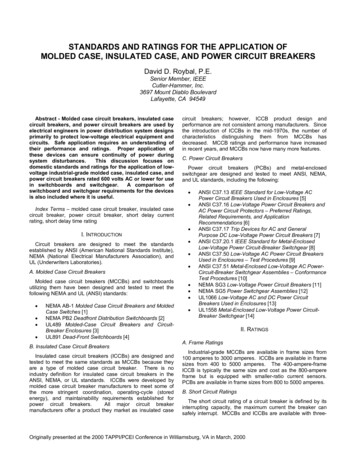
MCC RatingsIn addition to the various ratings of individual components usedin motor control centers, the overall ratings of the motor controlcenter must also be considered.Voltage RatingMotor control centers are rated for 600 volts. This is themaximum voltage that can be applied to a motor control center.A motor control center can be connected to a lower voltage.A motor control center, for example, might be connected to athree-phase, 480 VAC power supply.Horizontal BusCurrent RatingThe horizontal bus on Siemens motor control centers are madeof tin or optional silver plated copper. They are available with600A, 800A, 1200A, 1600A, and 2000A current ratings.47
Vertical BusThe vertical bus on the TIASTAR motor control centers areavailable with 300A and 600A ratings.Bus BracingMotor control centers must be capable of withstanding thelargest potential short-circuit current which can occur in theselected application. The amount of short-circuit currentavailable depends on the amount of power available to a facility.Short-circuit current can be thousands of times higher thannormal current. Bus bars must be braced to withstand thispotential current. Siemens bus bars are braced for 42,000 AIC(ampere interrupting capacity) with optional bracing available to100,000 AIC.48
Temperature RiseThe bus bars are the major current carrying component of themotor control center. Before a motor control center is operated,bus bars are at the temperature of the surrounding air. This isknown as ambient temperature. Temperature rises in the motorcontrol center bus bars during operation. The combination ofambient temperature and allowed temperature rise equals themaximum temperature of the bus bars.NEMA and UL both have standards concerning the maximumtemperature rise of bus bars used in motor control centers.NEMA limits temperature rise to 65 C based on an ambienttemperature of 40 C (104 F), for a maximum operatingtemperature of 105 C. UL limits temperature rise to 50 C basedon an ambient temperature of 40 C (104 F), for a maximumoperating temperature of 90 C. Electrical equipment bearing aUL mark must meet or exceed this standard.Siemens motor control centers meet or exceed NEMA andUL standards. Bus bars in Siemens motor control centers aretested with a maximum temperature rise of 50 C over 40 C(104 F) ambient.49
EnclosuresNEMA defines an enclosure as a surrounding case constructedto provide a degree of protection to personnel against incidentalcontact with the enclosed equipment and to provide a degreeof protection to the enclosed equipment against specifiedenvironmental conditions (NEMA Standard 250 - section 2,definitions).The following brief descriptions cover enclosures available forSiemens motor control centers.Type 1 Enclosure50Type 1 enclosures are intended for indoor use primarily toprovide protection against limited amounts of falling dirt andcontact with the enclosed equipment in locations whereunusual service conditions do not exist.
Type 1 Gasket FrontType 1 gasketed front, general purpose, indoor enclosure hasthe same use as Type 1 except the front of the enclosure isgasketed. In addition the following parts are gasketed:Unit separator anglesRight-hand side of front of unitsBottom horizontal cross tiesLip on top platePilot-device panelHandle mechanismBottom horizontal wireway cover plateSide holes are pluggedType 2, Drip-ProofType 2, drip-proof is an indoor enclosure intended to protectequipment from falling noncorrosive liquids and dirt. Theenclosure prevents the entrance of dripping liquid at a higherlevel than the lowest live part within the enclosure. Thisdesign is a Type 1 gasketed front, or Type 12, with a drip shieldmounted on top of the enclosure.Type 12 EnclosureType 12 enclosures are intended for indoor use primarily toprovide a degree of protection against circulating dust, fallingdirt, and dripping noncorrosive liquids. They are not intendedto provide protection against conditions such as internalcondensation.The Type 12 will provide a greater degree of protection than aType 1 gasketed enclosure. The following additional parts aregasketed:Hinged side of doorsTop platesWireway end-coversRear platesThere is no gap between sections, allowing for much greaterdust resistance. In addition, interconnection holes in the sidesheet assemblies are sealed. Bottom plates are included.51
Type 3R EnclosureType 3R enclosures are intended for outdoor use primarily toprovide a degree of protection against falling rain and sleet andprotection from contact with the enclosed equipment. They arenot dust, snow, or sleet (ice) proof. They will prevent entrance ofrain at a level higher than the lowest live part. The enclosure hasprovisions for locking and drainage.The enclosure entirely surrounds the motor control centerfor outdoor operation. The Type 3R enclosure is designedto accommodate bottom cable entry and exit only. The 3Renclosure is not a walk-in type design.NEMA and IECThe International Electrotechnical Commission (IEC) is anotherorganization that defines the degree of protection provided byenclosures. NEMA is primarily associated with equipment usedin North America. IEC is associated with equipment sold inmany countries including the United States.The IEC designation consists of the letters IP followed by twonumbers. The first number indicates the degree of protectionprovided by the enclosure with respect to persons and solidobjects entering the enclosure. The second number indicatesthe degree of protection against the ingress of water. Thefollowing chart provides an equivalent conversion betweenNEMA and IEC designations.52NEMAIEC123R12IP10IP11IP14IP52
Classification and Types of WiringNEMA has established two classification standards (Class Iand Class II) and three types of wiring (A, B, and C) used in theconstruction of motor control centers. These are specified bythe customer.Class IClass I consists of a grouping of combination motor controlunits in which each starter and motor operates independentlyof the other starters. The factory connects the combinationmotor control units to the vertical bus but does not provideinterconnecting wiring between combination motor controlunits, different vertical units, or remotely connected devices.Diagrams of the individual units only are supplied.Class I, Type A WiringType A wiring is only available on Class I motor controlcenters. The motor control center manufacturer connects thecombination motor control unit to the vertical bus via the stabson the back of the unit. Power is applied to the circuit breakerfrom the vertical bus. The circuit breaker is factory wired tothe motor starter. The customer connects the motor leads andcontrol wiring to the motor starter. There is no interconnectingwiring between combination motor control units.53
Class I, Type B WiringTypically pilot devices, such as indicator lights, pushbuttons, andselector switches, are used with Class I, Type B wiring. Type Bwiring is divided into two designations: B-d (-d for connectionof load wires directly on starter or contactor terminals) and B-t(-t for connection of load wires to unit mounted load terminalblocks).When Type B-d wiring is specified, terminal blocks are furnishednear the wireway for control circuit connections. Motor leadsare connected directly to the overload relay terminals.When Type B-t wiring is specified, terminal blocks are furnishednear the wireway for control circuit connections and for motorstarter leads. Type B-t wiring can be used on starters up tosize 3.54
Class I, Type C WiringWith Type C wiring, a master terminal block is provided in eitherthe top or bottom horizontal wiring gutter. The manufacturerof the motor control center brings the control wires from eachcontrol unit to the master terminal block. The installer is thenable to make his wiring connections at the master terminalblock. With Type C wiring, load wiring for combination motorcontrol units smaller than size 3 (50 HP) are connected tothe master terminal block. Load wiring for combination motorcontrol units larger than size 3 are connected directly to unitdevice terminals.55
Class IIClass II consists of a grouping of combination motor controlunits with interwiring and interlocking between the starters toform a complete control system. Wiring diagrams, includingthe interwiring, is furnished. Class II is generally specifiedwhen a group of motors requires sequencing, interlocking, orinterconnecting.Class II, Type BClass II, Type B wiring is similar to Class I, Type B wiring.Terminal blocks are furnished near the wireway. In addition,Class II, Type B wiring includes interconnecting wiring betweenmotor starters.56
Class II, Type CClass II, Type C wiring is similar to Class I, Type C wiring. Inaddition, Class II, Type C wiring includes interconnecting wiringbetween motor starters and vertical sections.Reference ChartThe following chart provides a handy reference whendetermining the class and type of wiring used in motor controlcenters.57
Cable EntryThere are several ways incoming power can be terminatedin a motor control center. Cable can be routed directly to theincoming power lugs, to main breakers or disconnects, or to aterminal block in a vertical section. In addition, incoming powercables can enter and exit the motor control center from the topor bottom depending on the application.Main Lugs58When using main lugs the amount of vertical space requiredvaries with the amperage rating. When the main lugs arelocated on the top, as in the following illustration, the verticalspace is taken at the top. A motor control center can also havethe lugs located at the bottom of the MCC. In the followingillustration, for example, main lugs rated for 600 amps arelocated on the top of the MCC. In this example 24” of verticalspace is required.
Main Lugs on Top,Top EntryIn the arrangement illustrated below incoming power cablesenter through the top of a vertical section and are connected tomain lugs.Main Lugs on Top,Bottom EntryIncoming cables can also enter from the bottom and connect tomain lugs located in the top section.Main Lugs on Bottom,Bottom Cable EntryLugs can also be supplied on the bottom of the vertical bus forbottom cable entry.59
Disconnect DeviceWhen a main disconnect device, such as a circuit breakeror fusible disconnect, is used, the disconnect is mounted inits own unit. The amount of space required depends on thedisconnect used. The space can vary from 12” to 72”.In the following illustration a main circuit breaker is used. Cableentry can be from the top or bottom of the vertical section.60
Review 51.The maximum current rating for a horizontal bus onSiemens motor control center is amps.2.The maximum bus bracing available for a Siemensmotor control center is AIC.3.The IEC equivalent of a NEMA Type 3R enclosure is.4.Identify the following types of Class I wiring:61
TIASTARTIASTAR is trade name of the motor control centers thatSiemens manufactures. Several mechanisms and features havebeen designed into TIASTAR. Many of these features will bediscussed in this section.62
DimensionsThe nominal height of TIASTAR is 90” high. The overall heightis 91 1/8” including a standard 1 1/8” base channel. There are72” of vertical space available for combination motor controlunits, with 12” at the top and 6” at the bottom for wiring. Thehorizontal power bus is located in the 12” of top space makingit easier to service. Each vertical unit will hold up to six 12” units(6 x 12 72). An optional pull box (top hat) can be suppliedwhen extra wire-bending space is required. Pull boxes can be12”, 18”, or 24” high.Vertical structures are 20” wide. A 30” wide unit is availablefor special units, such as large AC drives or transformers thatrequire more space. The vertical wireway is 4” wide on 20”wide sections. An optional 8”-wide wireway is available on 20”wide sections. Vertical units can be 15” or 20” deep.63
Back-to-Back MountingA feature of TIASTAR motor control centers is the ability tomount combination motor control units back to back. Thispermits mounting 12 combination motor control units in 72” ofvertical space. TIASTAR vertical units designed for back-to-backmounting are 21” deep.Back-to-back combination motor control units use the samestab-on connection as front mounted units.64
Basic ConstructionTIASTAR motor control centers offer two vertical bus designs.Front only structures with 42K or 65K bus bracing are suppliedwith an insulated vertical bus design standard. The vertical busbars are not physically isolated phase-to-phase.An optional isolated and insulated vertical bus assembly isavailable for front only 42K and 65K bus bracing. The isolatedand insulated vertical bus design is standard for 100K busbracing and all back-to-back structures.Combination motor control units can be interchanged and areeasily rearranged on either bus assembly. The unit supportbrackets can be repositioned to accommodate various sizeunits.65
Horizontal BusThe horizontal bus is connected to the vertical bus with atwo-bolt, U-shaped clamp utilizing spring washers to maintaintorque. This allows the bolts to be tightened from the front.Horizontal bus bars are shielded by a clear polycarbonate coverfor safety and easy visibility for inspection.Ground Bus66A horizontal ground bus is mounted in the bottom 6” of space.The horizontal ground bus is standard. An optional verticalground bus can be connected to the horizontal bus. When acombination motor control unit is instered into the MCC thevertical ground bus is the first item engaged. Likewise, whenthe unit is removed the vertical ground bus is the last thing tobe disengaged.
Wire Tie RodsRound wire tie rods are located in each vertical wireway to holdwire harnesses in place.Pilot DevicesPilot devices are mounted on a panel which latches onto theunit door with a simple tab-and-notch mechanism. The pilotdevice panel can be r
Siemens motor control centers. Type 1 Enclosure Type 1 enclosures are intended for indoor use primarily to provide protection against limited amounts of falling dirt and contact with the enclosed equipment in locations where unusual service conditions do not exist. 51 Type 1 Gasket Front Type 1 gasketed front, general purpose, indoor enclosure has the same use as Type 1 except the front of the .