Transcription
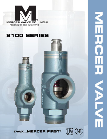
Telescoping Post IndicatorWall PostKENNEDYVALVEISO 9000ISO 14001
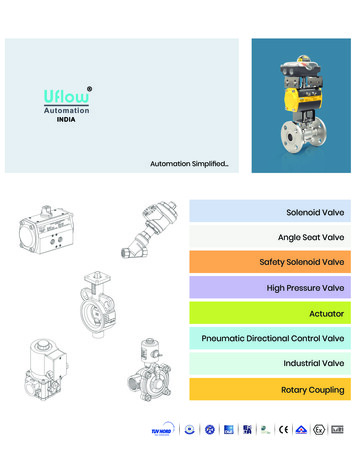
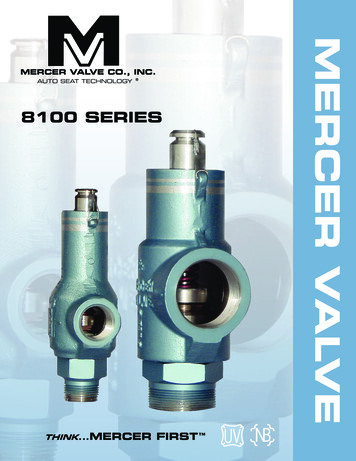
Telescoping Post Indicator2945 A1" SQUARE STEMMAX. 10"MIN. 7"9"FIELD ADJUSTMENT INSTRUCTIONS1. Remove the top section from the Indicator Postassembly.2. Loosen the telescoping barrel screw and adjust barrel tothe ground level.3. Cut the 1” square stem at a distance of 9” above the topof the barrel end.4. Set the “OPEN” and “SHUT” targets for the appropriatevalve size.5. Reattach the top section to the top of the IndicatorPost assembly.TELESCOPING BARREL 2945A TRENCH DEPTH LIMITSB SIZEC SIZED SIZEE �94”114”115”138”Updated 4/4/2014
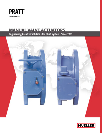
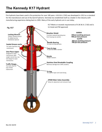
Indicator Post Parts ListPARTS LISTUpdated 4/4/2014DETQTY PART NO.DESCRIPTIONMATERIALP-113361270LOCKING WRENCHP-213024872(4-14”)OPERATING NUTP-31442639PP-413020912RETAINER O-RING226TOP SECTIONCAST IRONASTM A126CLASS BBRONZE ASTMB584 ALLOY864BUNA NP-52441980PWINDOW GLASSP-62443370POPEN TARGETP-72443371PSHUT TARGETP-81-TARGET CARRIERASSEMBLYP-8A13005802(4-12”)TARGET 4442411PTARGET CARRIERPLATECLAMP TARGETRETAINER#10-24X1/2” PANHEAD#10-24 HEX NUTP-91P-10 1P-11A 2”)P-193444355PP-204444357PP-214442484PCAST IRONASTM A126CLASS BLEXAN-UVSTABILIZEDCASTALUMINUMCASTALUMINUMBRONZE ASTMB584 ALLOY8641/16” SHEETMETAL16. GA 302 SSZINC PLATEDSTEELZINC PLATEDSTEEL1/2” NPT PIPE PLUG MALL. IRON3/8” EYEBOLT #23 FORGED STEEL3/8-16X1” HEXZINC PLATEDCAPSCREW (ADJ.STEELPOST)STEM 1” SQUAREAISI M1020HRSCRANE COUPLING CAST IRONASTM A126CLASS BCOTTER PINBRASS3/4” HEX HEADZINC PLATEDSCREWSTEELTELESCOPING5” D.I. Class 52BARRELANSI A21.51LOWER STANDPIPE 4” DI Class 52(ADJ. POST)ANSI A21.51BASE FLANGECAST IRONASTM A126CLASS B5/8”X1” HEX HEAD ZINC PLATEDSCREWSTEEL5/8”X2 1/4” HEXCAPSCREW5/8” HEX NUTZINC PLATEDSTEELZINC PLATEDSTEEL
INDICATOR POSTMODEL 2945A AND 2945 UL/FMINSTALLATION INSTRUCTIONS %.% 9 6!,6%Installation - 4HE VALVE SHOULD BE OPENED TO THE FULLY OPEN POSITION BEFORE PROCEEDING WITH THE)NDICATOR 0OST INSTALLATION 1.Disassembly of the Indicator Post Unit4ELESCOPING "ARREL 5NITSs2EMOVE THE 4OP 3ECTION FROM THE END OF THE BARREL s,OOSEN THE TWO SCREWS ON THE BARREL AND SLIDE OFF THE TOP OF THE STANDPIPE &IXED ,ENGTH 5NITSs2.Base Flange Installation:s3.2EMOVE THE 4OP 3ECTION FROM THE END OF THE STANDPIPE !TTACH THE BASE FLANGE ALONG WITH THE STANDPIPE TO THE VALVE PLATE USING THE FOUR BOLTSAND NUTS PROVIDED Grade Line Adjustments:4ELESCOPING "ARREL 5NITSs,OWER THE BARREL OVER THE STANDPIPE UNTIL THE GRADE LINE MARK ON THE BARREL IS AT GROUND LINEHEIGHT AND THEN TIGHTEN THE TWO SCREWS SECURELY &IXED ,ENGTH 5NITSs4.#UT THE REQUIRED LENGTH OFF THE BOTTOM OF THE STANDPIPE SO THAT THE INDICATED GRADE LINE OFTHE STANDPIPE IS AT THE GROUND LINE HEIGHT AND THEN SECURE TO THE BASE FLANGE BY TIGHTENINGTHE TWO SCREWS Extension Rod Adjustments:,OWER THE STEM INTO THE BARREL STANDPIPE PLACING THE CRANE COUPLING OVER THE VALVE OPERATING NUT )T IS NECESSARY THAT THE STEM ENGAGE THE OPERATING NUT A MINIMUM OF INCHES BUT NOT MORE THAN INCHES 4O CHECK FOR CORRECT ENGAGEMENT THE END OF THE STEM SHOULD BE FROM INCHES TO INCHES ABOVETHE TOP OF THE STANDPIPE &IXED ,ENGTH 5NITS OR THE TOP OF THE TELESCOPING BARREL 5.Target (Open and Shut) Adjustments2EMOVE THE TARGET ASSEMBLY FROM INSIDE THE BODY BY ROTATING THE OPERATING NUT COUNTERCLOCKWISE ,OOSEN THE TARGET RETAINER SCREWS BUT DO NOT REMOVE THEM Updated 05/02/2012Updated4/4/2014Kennedy Valve/Indicator Posts17-7
INDICATOR POSTMODEL 2945A AND 2945 UL/FMINSTALLATION INSTRUCTIONS %.% 9 6!,6%5. Cont’dOpen Left Valves-OVE THE /0%. TARGET TO THE TOP OF THE PLATE .OTE 0OSITION OF THE 3(54 TARGET CAN BE DETERMINED BY THE FOLLOWING CHART 6ALVE3IZE 'ATE6ALVE h!v 276ALVE h!v See Note (1)0OSITION THE 3(54 TARGET AS INDICATED BELOW AND TIGHTEN THE RETAINER SCREWS UNTIL SNUG !VOID OVER TIGHTENING 2EPEAT THE PROCEDURE FOR THE OTHER SIDE Note (1): Resilient Seat Gate Valves 14" and larger, require special targetmechanism threads. Contact Kennedy Valve EngineeringValve size target location markings64519 16Adjustment of target:1. Grasp target at midpoint & pullout slightly.2. Slide up or down to desiredlocation & then release grip.Open Right Valves4HE PROCEDURE IS SIMILAR AS FOR OPEN LEFT BUT WITH TWO DIFFERENCES ! 4HE OPEN TARGET IS PLACED below THE SHUT TARGET " 4HE OPEN TARGET IS PLACED AT THE VERY bottom OF THE PLATE 4HE POSITION OF THE SHUT TARGET ABOVE THE OPEN TARGET IS THEN DETERMINED AND SET AS DESCRIBED ABOVE Maintenance ,UBRICATIONLubricate upper bearing area at least once per year, by applying several drops of light machine oil or food gradegrease to the areas where the Operating Nut (P-2) contacts the Top Section (P-4).Access to this area is gained by removing the Locking Wrench (P-1) and lifting upward on the Operating Nut (P-2). /PERATION4HE TARGET MECHANISM WILL TRAVEL OFF THE THREADS OF THE OPERATING NUT IN BOTH DIRECTIONS SHOULD THE TARGETS ORTARGET MECHANISM BE POSITIONED INCORRECTLY 3HOULD THIS HAPPEN READJUST TARGETS )F THE TARGET MECHANISM FALLSFROM THE OPERATING NUT IT WILL BE STOPPED A SHORT DISTANCE BELOW THE WINDOW 17-8Kennedy Valve/Indicator PostsUpdated 05/02/2012Updated4/4/2014
2945 (A) Vertical Indicator Post - Changing the Lower n (2) 3/4" - UNC Bolts (Items P-15) that retain the Telescoping Barrel (Item P-16)to the lower Standpipe (Item P-17)Working in a safe manner lift off the entire top assembly (Items P-1 through P-16)from the Telescoping Barrel and Base FlangeRemove the Stem (Item P-12) and Crane Coupling (Item P-13) sub-assemblyLoosen the 3/4" -UNC Bolts 19) that retain the Lower Standpipe to the Base FlangeRemove the existing Lower Standpipe and set the new one into the socket in the Base Flange.Securely tighten the bolts that were loosened in Step 4 (50 to 100 ft.-lb)Working safely, slide the entire top assembly over the new Lower StandpipeTighten the (2) 3/4" - UNC Bolts that retain the Telescoping Barrel to the Lower Standpipe(Item P-15) - Tighten them securely enough to safely maneuver the Post in the fieldRemove the Wrench (Item P-1), the 3/8" - UNC Bolt (Item 11A) and the Eyebolt (Item P-10)Lift the assembly of the Top Section (Item P-4), Operating Nut (Item P-2), Target Carrier AssemblyItems P-6 through P-8), etc. from the Telescoping Barrel.If a longer Lower Standpipe has been installed it will be necessary to procure a longer Stem.Slip the Crane Coupling (Item P-13) over one end of the new Stem and cross drill a new,cotter pin hole through the new StemIf the Lower Standpipe just installed is shorter than the one it replaced the Stem will have to be cutBolt the Base Flange of the sub-assembly that includes the Base Flange, Lower Standpipe andTelescoping Barrel to the flange of the valve, using the 3/4" - UNC Bolts & Nuts providedby Kennedy ValvePlace the square socket in the Crane Coupling on the Stem & Coupling sub-assembly over the2" Square Nut at the top of the stem of the valveSee page 17-4 of the Kennedy Valve Product Catalog and follow the directions.NOTE: Kennedy Valve does offer for sale Couplings to extend StemsUpdated4/4/2014Updated 05/02/2012Kennedy Valve/Indicator Posts17-9
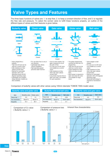
INSTRUCTIONS FOR EXTENDING A 2945A POSTLoosen the two 3/4" screws on top pipe section (near grade line at bottom of pipe). Pullapart the upper section from the lower pipe section. Place new extension coupling with newextension pipe over the existing lower pipe section. Tighten screws provided on the extension pipe and lower pipe (3/4" X 1" square head screw). Take existing stem and place thenew extension stem with coupling on top of original stem. Drill through stem and coupling(pilot holes provided on one side) then pin together with pins provided (1/4" X 3" br. cotterkeys). Place stem down the inside of new extension and lower pipe assembly aligning it onthe 2" square nut on valve. At this time, remove top section (with operating nut assembly)from off the top of indicator post standpipe (two bolts). Place complete upper section overtop of stem and align with the new extension pipe. Push together, adjust to desired height,and retighten the two 3/4" screws in top pipe section. Stem should be cut 7" - 10" abovethe pipe. Adjust open/shut plates per instructions and replace top section with stem nut (canalso be extended at bottom end).5./ 61 2 %3#2)04)/. UCTILE 0IPE AS REQD %XTENDER143 #OUPLING3ET 3CREW 5.#8 LG ,OWER %XTENSION 8417-10Kennedy Valve/Indicator Posts7%XT 3TEM #OUPLING %XISTING Updated05/02/20124/4/2014Updated3TEM3TEM#OTTER 0IN
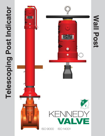
Angle Bracket Kitfor Wall PostWall Post2945 W ! SIZE (inches)4681012Centerline to CouplingA14.751922.5026.5030Minimum DImenison –Centerline of valve toCenterline of Indicator PostB252932.503640.375Minimum Centerlineof Valve to WallC778.3759.37510.50Wall Thickness (Reference)D66666Minimum Stem Lengthfrom WallE10101010102424243636Stem LengthNOTESKENNEDY VALVEAngle Bracket kit includes two equallength stems. Available kit lengthsare 18”, 24”, 36” and 52”. Stems areto be cut to length in field if valvesdon’t conform to table.a division of McWaneMADE INTHE USA %AST 7ATER 3TREET s 0 / "OX s %LMIRA .EW 9ORK s PH s FAX Updated4/4/2014P12013
Wall Post Parts ListWP-1WP-2PARTS LISTWP-3NO.ITEMQTYMATERIALPART NO.WP-1EYEBOLT 1/2-UNC2” LONG1STEEL440253PWP-2NUT 1/2-UNCPLATED1STEEL477495PWP-3WASHER 5/8PLATED1STEEL445834PWP-4HANDWHEEL 14”DIA.1DUCTILE IRON436015P O/L436032PO/RWP-6RETAINER O-RING#2261BUNA442639PWP-7OPERATING STEMNUT1BRONZE ASTM B584ALLOY 8643024872WP-11TOP SECTION1CAST IRON ASTMA126 CLASS B3020942WP-12TARGET CARRIERNUT1BRONZE ASTM B584ALLOY 8643005802WP-13WINDOW2LEXAN-UV STABILIZED441980PWP-16TARGET CARRIERPLATE21/16” SHEET METAL443347PWP17AOPEN TARGETPLATE2CAST ALUMINUM443370PWP17BSHUT TARGETPLATE2CAST ALUMINUM443371PWP-18CLAMP TARGETRETAINER416. GA 302 SS440736PWP-19#10-24 HEX NUT4ZINC PLATED442411PWP-20#10-24X1/2” PANHEAD SCREW8ZINC PLATED444171PWP-21PIPE PLUG-1/2” NPT 1STEEL443476PWP-22STEM 1” SQUARE1AISI M1020 HRS445312LWP-23COTTER PIN1BRASS442190PWP-24CRANE COUPLING1CAST IRON ASTMA126 CLASS B318035&WP-273/8” EYEBOLT #231FORGED STEEL440254PWP-283/8-16X1” HEXCAPSCREW1ZINC PLATED STEEL444306PWP-29BASE FLANGE1CAST IRON ASTMA126 CLASS 24Updated 4/4/2014
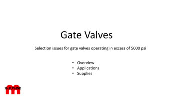
Pit Post2945 P ' &% ' & % LOCKINGWRENCHOPERATINGNUT'& & ;k ' SPACER E # PIPEPLUGBOLTTARGETCARRIER NUTOPENTARGET # NUT %% SHUTTARGETCLAMPTARGETRETAINERPAN HEADSCREW1” SQUARE STEMBOLT & & BASE FLANGECOTTERPINCRANECOUPLINGBOLTNUTUpdated 4/4/2014*SEE PAGE 3 (INDICATOR POST PARTS) FOR REPLACEMENT PARTS
Kennedy Valve# & 8 5 10 1( /E9#0' 0% ' 9CVGT 5VTGGV Ŗ 'NOKTC 0GY ;QTM 2 1 QZ 2*10' Ŗ (#: Updated4/4/2014Updated 05/02/201227 A- 8A
by Kennedy Valve 14. Place the square socket in the Crane Coupling on the Stem & Coupling sub-assembly over the 2" Square Nut at the top of the stem of the valve 15. See page 17-4 of the Kennedy Valve Product Catalog and follow the directions. NOTE: Kennedy Valve does offer for sale Couplings to extend Stems Updated 05/02/2012Updated 4/4/2014