Transcription
Nov.2008No. 02Newsletter for Materials Science & TechnologyresolutionSave Our MemoryA Look Inside the Restoration of Historic PhotosCombined Precision for Non-ContactSurface MetrologyThe First Dual Core Microscope forConfocal and Interferometry ProfilingResearch for the Optimal StructureMagnetic Fields Optimise Metal Alloys
EDITORIALDear Reader,Type the keyword ’nanotechnology’ into Google and you’ll get well over 15 million hits. Early in the 21stc entury people were still talking about the technology of the future. Now nanomaterials are already anintegral part of our everyday life: dirt repellent spectacle lenses, windscreens and textiles, scratchproofpaints, efficient catalytic converters, transparent solar cells, high-speed cell phone chips or LEDs in trafficlights are but a few of the examples of the many applications of nanotechnology. However, we have only justbegun to comprehend and harness the phenomena and laws of nano-science – the fundamental structuresand the processes occurring in materials at atomic and molecular level.Tapping further into the untold potential of new, nanotechnological products calls for new tools capable ofmeasuring and modeling the structures on a scale of one atom to 100 nanometres. The new DCM 3D measuring microscope is just such a tool. Combining confocal and inferometric technology for the first time,it can contactlessly measure surface geometries to a resolution of 0.1 nanometres. And when it comesto preparing specimens for nanometric and microstructural analysis, Leica Microsystems has a range of innovative instruments such as the Leica EM TXP and the Leica EM TIC020.However, this edition of reSOLUTION is not devoted to the future alone. Remember those old family photographs of your grandparents or great-grandparents; fading photographs in danger of being lost to posterity for ever? To keep these memories alive for future generations, the specialists at Fratelli Alinari utilisecutting-edge technology – such as stereoscopy with all its imaging and documentation applications.We hope you enjoy this edition of reSOLUTION. In particular, we look forward to your opinions and comments.To find out how to post your opinions and comments, and how we propose to thank you for your feedback,please turn to page 16.Have fun reading!CONTENTSAnja SchuéDanilo ParlatanoCorporate Communications European Marketing Manager Industry2 reSolutionC U LTU RAL HERITAGEP RO D UCT NEWSSave Our Memory03A Look Inside the Restoration of Historic PhotosFor Different Challenges Every DayNew Routine Stereomicroscopes15TECH N OLOGYLet the System Do the JobAll-In-One Target Surfacing System for SEM,TEM, and LM17Leica DM750 PFor the Future of the Experts19YO U R O P I N IO N CO U N TS !16E V E N TS19I M P RI N T19Combined Precision forNon-Contact Surface MetrologyThe First Dual Core Microscope for Confocaland Interferometry Profiling06RESEARCH & D E V ELOP M EN TResearch for the Optimal StructureMagnetic Fields Optimise Metal Alloys10THEORY & P RACTICEBeware of Pixel Mania13
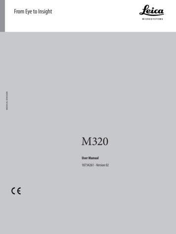
Cu l t u r a l H e r i t a g eA Look Inside the Restoration of Historic PhotosSave Our MemoryIn 1852 Leopoldo Alinari, with his brothers Giuseppe and Romualdo, founded aphotographic workshop in Florence, which is at the heart of the firm that stillbears his name: Fratelli Alinari. It was the beginning of a unique endeavour thatspecialised in photographic portraiture, works of art and historical monuments,achieving national and international recognition. With the help of stereomicroscopy technology from Leica Microsystems Alinari is able to preserve the cultural heritage – our memory – for the future generations of professional restorers.The name of Alinariguarantees morethan 150 years of experience and stateof the art professional technology.Today there areover 2,750,000 b/wand colour negatives in various collections, from plates to colourphotos, and over 900,000 vintage prints, includingsalted paper, albumen, bromide prints, calotypenegatives, daguerreotypes, etc., preserved in thecollection of 6,000 original albums. These are worksby the greatest nineteenth and twentieth centuryphotographers, both Italian and non-Italian, but alsoby many other less-known professional and amateur photographers. In 2001 the digital archive wasinaugurated that continues to grow with images thatcan be viewed on line. Today there are over 450,000pictures available on the web (www.alinari.it).Alinari museum and libraryThe collection of the Fratelli Alinari Museum of theHistory of Photography was established in 1985 andcompleted with a gallery in 1997 in Palazzo Rucellaion Via della Vigna Nuova and now in Santa MariaNovella. The Alinari National Museum of Photo-graphy (MNAF) is currently located in the fifteenthcentury building known as ‘delle Leopoldine’. Theimportance of this museum is also illustrated by itscollection of cameras, advertisements, paper documents, frames and all those objects connected tothe photograph which can be considered an integral part of its history. Another ‘vital’ sector of themuseum is the library specialising in the history ofphotography, with over 20,000 books and journals.The various exhibitions and projects focus on theeducational aspect making the collections accessible to a heterogeneous public. One of the primaryaims of the MNAF is to create a network of scientific and artistic institutions on a regional, nationaland international level.Photographic restoration laboratoryOur restoration laboratory pursues conservationtreatment and restoration from the great publicarchives deposited in museums, libraries, institutes and academies to materials belonging to thearchives of industries and firms as well as privateindividuals. The laboratory is available for consultation and advisory services and various types of conservation treatment.The Alinari laboratory engages in conservationtreatment of many types of materials from the oldestdaguerreotypes to calotypes, photographic prints,rare negatives on paper, collodion and silver glassplate, up to the most recent colour proofs and negatives. We use the latest generation of Leica Micro systems’ stereomicroscopes, Leica M205 C withFusionOptics , video and 3D analysis for acquiring,storing, annotating and displaying high quality images of our heritage which needs restoration. Thanksto the fact that the microscope has an integrateddigital camera, we can work using a large high definition flat screen instead of looking through the binPhotos: Alinari ArchivesFig. 1: The 150 years of Alinari’s activity were celebrated with a special national stamp.Sam Habibi Minelli, Alinari 24 OREreSolution 3
Cu l t u r a l H e r i t a g eocular tube of the microscope, thusallowing team collaboration.In collaboration with the state institute for art restoration in Florenceand the Italian Ministry of Culture,Alinari holds nine professionalcourses dedicated to the restoration of photographic materials. Thetarget audience are professionalrestorers, archivists, historiansand researchers who already havea good background in these topics.The courses include theoreticaland practical experiments using theLeica M205 C. The microscopic analysis supportsthe recognition of the original material, the analysisof the conservation status and effects of differentmethods of restoration.The courses run by Alinari in collaboration withcompanies, universities and institutions offer aunique opportunity for teaching and providing continuous upgrades of knowledge to professionals onhow to preserve the cultural heritage: photographicdegradation is an intrinsic process due to the natureof photography. In fact, it is generated by a chemical and physical alteration of the light on the photosensitive substances. The restorer and conservation managers aim at slowing down this process,where possible, by operating on the micro ambiance(conservation cases and boxes) and on the macroambiance (archive rooms and t hermo-hydrometricalparameter management: humidity, lighting, quality of the air, temperature, etc.). After appropriateanalysis and the recognition of the photographicprocess, the restorer can execute direct restorationof the photography.Our professional courses take advantage of thedigital management of the microscope: we projectthe microscope view through the control panel ofthe microscope, we provide live micro-navigationand 3D views of the degradations. The researcherand the restorer can annotate the pictures using awide range of tools for measurement and reporting.Video sequences are executed to see and evaluatehow some chemical agents react on the paper or onother photographic surfaces. With the multi-pointfocus we obtain images which could not be realiseduntil now: better quality and more information on theobject under analysis.Alinari is going to set up a lot of new research projects to respond to the needs and scenarios providedby the restoration laboratory while using microscopetechniques.Fig. 2: Restoring laboratory usingmicroscopy techniques4 reSolutionExternally offered servicesAlinari offers access to its collection and laboratory for external researchers and companies forcollaborative research activities, general knowledge and expertise. Our services are also offered togovernment bodies for analysis and reporting aboutphotography authentication, courses/workshopsand publications for safeguarding photographiccollections, such as ANAI (Associazione NazionaleArchivistica Italiana), and the Ministry for CulturalHeritage and Activities.Stereomicroscopy inphoto restorationat Alinari’s Recognition of the photography(Daguerreotype, Albumin, etc.) Diagnostics of the preservation status(the restorer detects, analyses and reportsthrough a protocol form about all possiblephysical and chemical degradations: scratches,abrasions, craquelures, fading, mould, etc.) Verifying the restoration workflow Monitoring the preservation status Restoration and preservation of the originals A nalysis of the original supports(glass, paper, daguerreotype, collotype, etc.) Training for internal and external experts:cataloguers, museum management Reporting of biological/physical/chemicalalteration of the picture and its support Implementation of a data structure formonitoring large collections Collecting data and populating a Ground Truthas input to R&D Release of guidebooks, reference tablesand chart flowsContactSam Habibi Minelli, Head of the Research Applications Center at Alinari: sam.minelli@alinari.it
Cu l t u r a l H e r i t a g eVoices of Alinari’s customersDr. Hans Petschar, Director Picture Archives Austrian National Library: “It is amazing to see how thework of the restorer can be improved by this technology: you can analyse, document, report and reducethe effort whilst improving the quality of the results.”Roger Bruce, Director of Interpretation, Museum of Photography at George Eastman House, Rochester,New York, USA: “It is important that cultural heritage conservators trust the accuracy and integrity oftheir tools. Technology from Leica Microsystems, known worldwide for its refined image quality andoptical perfection, inspires confidence in the precision and consistency of our professional judgment.”Geneviève Aitken, responsible for documentation studies, new information technologies at the Centrede Recherche et de Restauration de Musées de Louvre, Paris, France: “The Leica Microsystems technology helps enormously and opens new opportunities for restoration and conservation of old photographs and documents.”Frank Grossmann, CEO Colour-Science AG, Bäretswil, Switzerland: “The Leica M205 C microscopeadds superior quality in the research and diagnostic field thanks to its top notch features.”Alinari events/courses supported by Leica MicrosystemsNovember 2008 – March 2009: Corso di Conservazione e Restauro dellaFotografia Fratelli Alinari. Fondazione per laStoria della Fotografia – Opificio delle PietreDure, Florence, ItalyNovember 2009: Restoration event “Fiera del Restauro”,Florence, Italy.reSolution 5
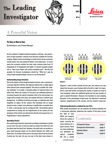
TechnologyThe First Dual Core Microscope for Confocal and Interferometry ProfilingCombined Precisionfor Non-Contact SurfaceMetrologyDr. Roger Artigas, Sensofar-Tech S.L.In recent years, interferometers and optical imaging profilers based on confocal technology have been competing fiercely to conquer the non-contact surfacemetrology market. They are both capable of accurately and reliably measuringsurface topographies on a millimetre to nanometre scale. Today, Leica Microsystems and Sensofar present a new complete solution able to outperform all existing systems due to its unique combination of techniques. The DCM 3D is the firstdual core 3D measuring microscope which combines both confocal and interferometry techniques. In addition to its compact and robust design, the DCM 3D is acomplete tool that is ideal for obtaining a super fast, non-invasive assessment ofthe micro- and nanogeometry of technical surfaces, in multiple configurations:From R&D and quality inspection laboratories to robotic driven systems during online process controls, the new DCM 3D is able to serve a wide range of applicationswhere high-speed and high resolution measurements down to 0.1 nm are needed.Unique combinationThe dual core 3D measuring microscope DCM 3D offers a unique combination of confocal and interferometry in a single sensor head. The core technology is based on a fast reaction microdisplay placedin the position of the field diaphragm. Bright field, interferometric and confocal images can be generatedby the control of the microdisplay. The non-movingpart concept, the confocal microdisplay (MD), twolight sources and two cameras (one colour and onemonochromatic) achieve high accuracy 3D measurements and unlimited depth of focus.Confocal MD technology allows measurements ofsmooth to rough surfaces, of topographical differences ranging from 1 nm to several mm, and up to 70degrees of local slope. In comparison to Laser Scanbased systems or Spinning Disc, MD confocal technology needs no moving mechanical parts, increasing both image stability at high magnifications andlight efficiency, and enhancing reliability and flexibility. Along with a LED based light source, MD technology prolongs instrument lifetime, reducing servicingand avoiding the cost of expensive spare parts.Surface measurements are achieved in seconds.The system is easy to use. Just place your sampleunder the microscope, focus and click “Acquire”. Itonly takes a few seconds (typically less than 5) toget a 3D view of the surface comparable to thoseacquired with a scanning electron microscope, in afraction of the time.Fig. 1: The DCM 3D6 reSolution
technologyFig. 2: Confocal, VSI and PSIoptical profilometry3D profiling and unlimited depth of fieldAs an example, the paint adhesion ability on a steelsurface is characterised. After polishing, the steelwas too smooth to allow good adhesion of an enamel-based composition. To increase the adhesionthe steel is processed with an acid attack to createmicro-valleys. This enables the paint to penetratefurther into the surface, increasing the effectivecontact area and improving adhesion to the upperlayers. As a result the paint is fixed hard. If the micro-valleys are too deep, however, the upper layerof the paint tends to follow the shape of the valleysin the underlying steel surface. On the other hand,if the microstructures are not deep enough, there isno adhesion effect.With the DCM 3D it is possible to inspect the surfaceand obtain suitable quality parameters to decide ifthe surface treatment is adequate or not. Alreadyafter placing the surface under the microscope, it iseasy to get a good idea of the depth of the microvalleys. The real-time confocal image allows you tofocus on top of the surface, move the focus down tothe valleys and take a direct reading of the depth.After clicking the “Acquire” button to get a 3D view,the confocal scan is so fast that you don t get timeto follow what is happening. A pseudocolour displayof the topography is shown on the screen with clearpresentation of the micro-valleys. Figures 3 and 4show the result of such a measurement. In orderto get a quantitative analysis of the micro-valleys,the 3D analysis software included with the system,called SensoMAP, was used.The software automatically segments the regions ofthe upper structures and the regions of the valleys.The volume distribution of the segmented regions(Fig. 5) was a suitable indicator for this purpose. Another useful parameter is Sdr (hybrid parameter, ISO25178). This parameter represents the proportion ofthe 3D surface that has been formed to the verticalprojection of this area. Thus, a plane surface has aratio of 1:1, while a surface with valleys increasesthe 3D area and thus this value. In our case we concluded that the optimum value should be 1:1.33, thatis, a 33% increase of effective area.Outperforming any profiling technologyA unique benefit of the DCM 3D is the fact that itincorporates two CCD cameras. One is a colourcamera used for bright field inspection, while a highquality monochromatic CCD is used as a metrological detector. During the 3D measurement of an area,a high resolution and high contrast confocal imageand an infinite focus colour image are acquired simultaneously. The analysis software allows 3D imaging of the surface in different colour modes suchas pseudocolour display of the topography, confocalstack, infinite focus colour image and high resolution confocal luminance with the chrominance signalof the colour camera.Fig. 4: Three dimensional view of the surface under inspectionOne of the main confocal benefits for 3D profiling isits flexibility to use microscope objectives originallydesigned for bright field microscopy. This meansthat the ideal optics are generally available to matchthe desired application, such as objectives with longfree working distances for large topography variations within the sample or for sample geometriesthat would collide with conventional objectives, objectives with an adjustable collar ring designed tofocus through coverslips, objectives for LCD inspec-Colour bright fieldConfocalUnlimited depth of fieldDepth CodedFig. 3: Microscope modesreSolution 7
TechnologyFig. 5: Left: microvalley segmentation,right: volume distribution of themicrofragmentations182910tion, and objectives for water immersion. Nevertheless, the numerical aperture of the objective limitsthe depth of focus and thus the height resolution.Low magnification objectives have lower NAs andconfocal 3D measurements tend to be noisier. TheDCM 3D achieves the highest measurable surfaceheight range by its unique combination of confocaland interferometry technology.In contrast to confocal technology, depth discrimination of phase shift interferometry (PSI) and vertical shift interferometry (VSI) does not depend onthe objective’s NA but on the light source properties. Despite PSI height resolution being down to0.1 nm, the maximum measurable height is limited to250 nm by optical laws. Nevertheless, the confocal interferometry combination allows measurementsfrom 0.1 nm to several mm. Figure 8 shows the resultof measuring a 10 nm step height standard with PSItechnology, a height resolution not possible withconventional confocal technology.95 100 105 110 115 120 125 130 135 140 145 150 155 160 µmThe DCM 3D is driven by field-proven SensoSCANsoftware. This package controls the whole systemand also allows several 2D/3D measurements. Inaddition, the system is fully compatible with SensoMAP, one of the most advanced 3D analysis packages for microscopic analysis of surfaces. Whenautomatic 2D analysis is needed, the system isalso compatible with the well known Leica Imaging Analysis Systems Leica Application Suite, LeicaQWin and Leica Material Workstation.Leica interferometry objectivesand powerful analysis softwareThe DCM 3D uses Leica Interferometry Objectivesto provide additional benefits to cover customers‘needs. The full range of interferometry objectives(5x, 10x, 20x and 50x) can be used for both interferometry techniques PSI and VSI. A unique system oftip-tilting (tilting at right angles to the optical axis) isintegrated on each objective, dramatically improving the time and the ease of alignment between thesurface of the sample and the optical axis in order toobtain interference fringes with the best contrast.In addition each objective is equipped with a dialwith four different positions to change the amountof light reaching the sample. It is therefore possibleto analyse samples with all kinds of reflectivity, increasing the flexibility of the whole system.8 reSolutionFig. 6: 3D view of the bayer filter on the microlens array of a CCD
TechnologyReal Surface ColourFig. 7: Paper portion after ink-jet printing.Left: 3D view with bright field colourInformation, right: the same 3D view withpseudocolour display of topography.Depth Colour 50400450500550600 mmFig. 8: Step Height standard of 10 nmmeasured with PSI technology, a measure not possible with conventional confocal technology.New team of experts to support users in EuropeOscar Rodriguez, Sales Manager Iberia for the Industrial Division at Leica Microsystems:“The DCM 3D is a great example of the Leica Microsystems philosophy where pioneering and teamspirit have always been key drivers of innovation. The unique system combines confocal and interferometry technology to cover the broadest imaginable range of 3D measurement applications. This innovative technology and the outstanding Leica optics make DCM 3D the perfect choice for industrial3D imaging and measurement applications.However, a technology would be worthless without the people who use and continuously develop it.That is why we have assembled a team of application specialists which will provide technical supportto users of the new DCM 3D system in Europe. Our team is committed to action before you even beginusing the system. For instance, our engineers will analyse material specimens and work with you tospecify the main applications of your DCM 3D so the system is optimally configured for your needs.You can always rely on our application specialists to help you solve any problems you have. Workingin close co-operation with our development engineers, they will take your ideas and requirementsand turn them into new and innovative solutions for future applications in an ongoing process of improvement.”ContactDr. Roger Artigas, Vice President Optical Metrology,Sensofar-Tech S.L.: Artigas@sensofar.comMore information on DCM microsystems.com/products/DCM3DreSolution 9
R e s e a r c h & D e v e l o pm e n tMagnetic Fields Optimise Metal AlloysResearch for theOptimal StructureDr. Sven Eckert, Research Institute of Dresden-Rossendorf and Anja Schué, Leica MicrosystemsTo see how liquids can be made to flow, without being directly heated or touched,you only have to watch a raw egg explode in a microwave oven. Electromagneticforces can even melt metal at hotter than 1000 C. In the Magnetohydrodynamics study group at the Research Centre Dresden-Rossendorf (FZD) these complex interactions between electrically conductive liquids and magnetic fields areused to control the flow and solidification processes of liquid metal alloys. Theaim is to create optimised production processes for foundries. To analyse the microstructure of the metal, the scientists use an automated system consisting of a high-end microscope and Power Mosaic image recording software thatscans large surfaces of the samples in high-resolution single frames and combines these as a precise overall image for quantitative analysis.MF coilCoverSpecimen crucibleThermocouplesFree surfaceCrucible isolationPb-Sn alloyCopper cooling surfaceWater coolingVertical positions of thethermocouples:TE1 1,5 mm, TE2 12 mm,TE2 22 mm, TE2 32 mm,TE2 42 mm, TE2 52 mmFig. 1: Diagram of the experiment set-upThe automobile and aerospace industries in particular use components made of special alloys whichhave to satisfy constantly growing quality specifications. There is a demand for thinner, i.e. lightercastings. Sometimes they have to be more complexor larger at the same time and still have to withstandincreasing loads. The stability and load bearing capacity of an alloy mainly depends on its microstructure. Magnetic field flow during the solidification of metal alloys determines the transport of heatand material in the melt and thus the nucleation andgrain growth. An ideal, i.e. uniform fine-grain microstructure therefore requires controlled solidification of the casting.The German Community of Research Scientists(DFG) has set up a collaborative research centrecalled “Electromagnetic Flow Control in Metallurgy,Crystal Growth and Electrochemistry” at the Technical University of Dresden, the Research Centre inDresden-Rossendorf, the Leibniz Institute of SolidState and Material Research in Dresden and the TUBergakademie Freiberg to study specially tailoredmagnetic fields for optimised technologies in material processing. The application potential is tremendous. Nearly all industrial metals are obtained frommetal melts. The advantages of electromagnetic10 reSolutionstirring in terms of controllability and absence ofcontact are also being utilised here to research theinfluence of flow structures on the solidificationprocess of metal alloys.Optimal non-contact stirringThe scientists at the FZD are conducting a subproject together with the TU Dresden in which theyperform solidification experiments using lead-tinand aluminium-silicon alloys under the influenceof rotating magnetic fields (RMF) (Fig. 1 shows adiagram of the apparatus). The aim is to obtain materials with a fine-grained isotropic structure withalmost spherical crystals, also called globulites.Normally, the morphology of many alloys is dominated by columnar dendrites. As materials that solidifyin the form of globulites exhibit significantly bettermechanical characteristics, the growth of dendritescan be prevented by means of magnetically drivenflows in the melt bath. On the basis of already wellinvestigated RMF flows, the scientists at the FZDexamined the complex physical phenomena duringthe controlled solidification process to be able toelaborate an optimal stirring strategy for foundryapplications [4-6].
R e s e a r c h & D e v e l o pm e n tDetailed insights into the structure of RMF-inducedflow during solidification are given by numericalsimulations carried out in a sub-project at the Institute of Aerospace Engineering of the TU Dresden.The basic findings obtained from the analysis of theflow structures during the solidification processand their influence on the heat and mass transfer inthe melt will be directly used in another sub-projectat the Foundry Institute of the TU BergakademieFreiberg and transferred to real castings for aluminium and magnesium alloys.Modulated magnetic fieldsThe experiments showed that, given constantcooling conditions, the proportion of the globuliticstructure volume depends directly on the type andintensity of the electromagnetically driven flow andcan be controlled by a defined setting of the magnetic field parameters. For instance, a distinct grainrefinement was detected in the microstructureafter electromagnetic stirring (Fig. 2 and 3). At thesame time, however, undesirable flow-specific segregations were observed. The Dresden scientistsare therefore looking for a specific flow pattern thatleads to a fine-grained globulitic structure, but notto any segregation of the phase components.Results from the numerical simulations show that acontrolled modulation of the magnetic field amplitude may generate a suitable flow pattern that significantly reduces the degree of segregation. Thiswas taken as the basis for developing concepts foroptimising the time functions for the magnetic fieldparameters amplitude and frequency which are examined in the solidification experiments. This approach has already brought the first clear success[1, 2].To obtain a better understanding of correlationsbetween the flow field ahead of the solidificationfront and the features of the solidification structure,the ultrasound Doppler technique was further developed at the FZD for applications in metal melts.Using this technique, flow speeds can be measuredduring solidification in the liquid phase for the firsttime [7].Quantitative analysis of microstructuresMacroscopic examination of solidified metal cylinders already shows distinct differences caused bythe influence of RMF, or how columnar morphologycan be changed into globulitic morphology by temporal or spatial variation of the magnetic field (Fig.4). Microscopic analysis of cross- and longitudi-nal sections of the 5 cm thick and 6 cm tall samplecylinders enables quantitative analysis of grainsize, phase distribution and, in particular, the proportional volume of globulitic structure (Fig. 5). Toobtain a high-resolution image of the entire surfaceof the sample, the Rossendorf scientists use the highperformance image recording software Leica LAS Power Mosaic combined with a Leica DM6000 M automated research microscope (Fig. 6). The polishedmetal sections are automatically scanned at a rate ofabout 400 frames per minute and a complete image isproduced at the full camera resolution (Fig. 7).The system generates a mosaic of single imagesat high speed, high accuracy and focusing in manageable data formats. Special advantages of theproduct from Leica Microsystems: the optimisedoffset of the image overlap of 16 pixels between theindividual images and the autocalibration functiondirectly at the sample to compensate for the finestinaccuracies of stage movement and optics. Theindividual image size and the compensation of thecamera rotation are automatically set by the system. The focus positions can be interpolated overa random number of reference points dependingon t
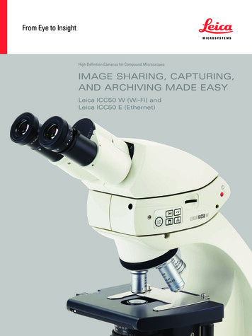
Fig. 2: Resolving power at low/high magnification low Magnification leica M205, 1x object field 14 x 11 mm r esolving power 75.8 lp/mm 4372 x 3280 Pixel 14.3 Megapixels high Magnification leica M205, 16x object field 0.9 x 0.7 mm r 525 lp/mm 1892 x 1419 Pixel 2.6 Megapixels 14 mm 0.9 mm