Transcription
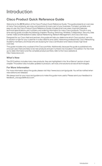
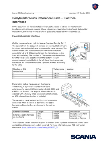
Scania (GB) Sales EngineeringIssue date 24th October 2019Bodybuilder Quick Reference Guide – ElectricalInterfacesIn this document we have collated several useful pieces of advice for mechanicallyinterfacing with a Scania chassis. Where relevant we have linked to the Truck BodybuilderInstructions, but should you have further questions please feel free to contact us .Electrical chassis interfaceCable harness from cab to frame (variant family 2411)The signals from the bodywork console are lead out to bodyworkfunctions on the chassis frame by means of a cable harness. Thecable harness runs from connector C494 in the bodyworkconsole to 1, 2 or 3 DIN connectors on the frame (close to thefront left mudwing). The number of DIN connectors depends onhow the vehicle was specified from the factory. The DINconnectors are located behind the left-hand front wheel, seeillustration. All DIN connectors are 7-pin and marked accordingto the table.Number of DINconnectors123PinsVariant codeMarking77 77 7 72411B2411E2411FC487C486 and C487C486, C487 and C488Extension cable harness on the frameAdditionally, it is possible to order multi-coreextensions for each of DIN connectors C486, C487 andC488 in 2m, 8m and 12m lengths. When the truck isordered with a factory-fitted extension cable harness,an ADR-classed junction box is included.The extension cable harness and junction box are notconnected when the truck is delivered. The cableharness and junction box are located in the cab fortransit.Extension HarnessExtension cable harnesson the frameLength2m8m12 mVariant code3023A3023D3023CDescriptionComplete with ADRjunction box ifordered ex-factoryThese options can be specified at point of chassis order – please advise your Scania Salescontact to add the relevant code if required. For more information, see TBB Instructiondocument: https://til.scania.com/w/bwm 0001083 01
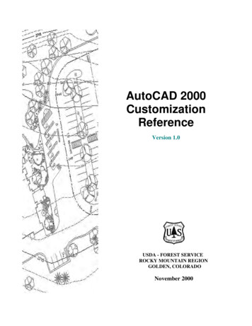
Scania (GB) Sales EngineeringIssue date 24th October 2019Power and Ground - connection to chassis.Power for bodywork - Low currentconsumptionIdeally, use the bodywork central electric unit P9 forthe power supply to bodywork functions. Themaximum permitted power output from the bodyworkcentral electric unit is a total of 90 A. The poweroutput is split between the following types of powersupply: 15 voltage: The maximum permitted poweroutput is a total of 30 A for fuses F7-F12.30 voltage: The maximum permitted power output is a total of 60 A for fuses F1-F6.Further details on the P9 electrical unit are given in the following TBB instructions:https://til.scania.com/w/bwm 0001046 01Power for bodywork - High current consumptionIf a greater power output is required than thebodywork central electric unit is dimensionedfor, a power supply must be taken fromchassis central electric unit P11, positiondesignation P11-F, which has a maximumpermitted current draw of 250A.The chassis central electric unit P11 is acentral electric unit for the vehicle’s main fuses, and it is positioned behind the left-handfront wheel, see figure. The fuses are of mega fuse type, rated between 40 A and 250 A. Inthe chassis central electrical unit, there is an option to connect large current consumers.Cable harnesses from, for example, the batteries, starter motor and any bodywork functionsare connected to the chassis central electric unit. For bodywork functions, connection pointP11.F is usually used, but no fuse for these comes factory-supplied. The fuse is fitted by thebodybuilder.If the P11.F connection is in use, the following connection positions can be used forbodywork functions, if the positions are available: P11.GP11.JP11.KP11.LP11.MFurther details on the P11 electrical unit are given in the following TBB instructions:https://til.scania.com/w/bwm 0001157 01
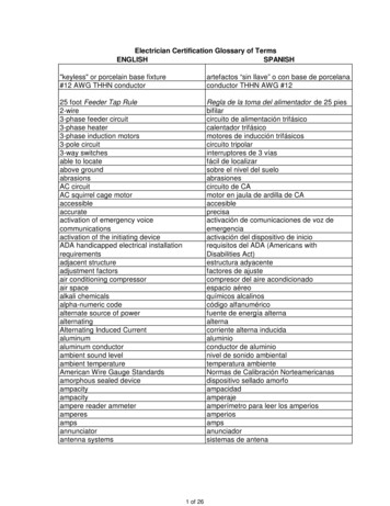
Scania (GB) Sales EngineeringIssue date 24th October 2019Grounding on frameThe chassis has two ground connections forbodywork functions, G46 and G47. The groundscrews are designed with an external M10thread on the screw flange. This makes itpossible to connect cables without looseningthe screw from the frame side member.The battery ground screw, G32, must never beused for grounding of bodywork functions.All grounding for bodywork functions on thechassis frame must be connected to the lefthand frame side member. Grounding in theright-hand frame side member will cause voltage drops.When it is not possible to use the regular ground connections intended for bodyworkfunctions, an additional ground connection can be installed in a more suitable location in theleft-hand frame side member. Scania ground screw (part number 2 261 990) must alwaysbe used and the relevant instructions followed.Grounding in CabIdeally, use the ground connection in thebodywork central electric unit for grounding inthe cab. The ground connection is designatedG70 and the maximum permitted current is 90A.Additionally, the cab has five junction blocksfor ground connection. Depending on vehicleconfiguration, some ground connections maybe occupied. The maximum permitted load perjunction block is 6.4 A. The maximum permittedtotal load for all junction blocks is 32 A. Use the junction blocks G1, G2 and G3 ifground connections are required behindthe instrument panel.If ground connections are required in theroof shelf use the junction blocks G64 and G65.Further details on the power supply and grounding are given in the following TBBinstructions: https://til.scania.com/w/bwm 0001038 01
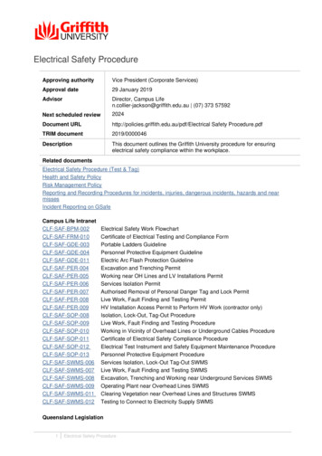
Scania (GB) Sales EngineeringIssue date 24th October 2019Mounting additional side marker and tail lampsAdditional Side Marker lampsAdditional Scania side marker lamps may be fitted in thefollowing ways: Connection via connector C450:For vehicles manufactured as of 2017-03-03,additional side marker lamps can be connecteddirectly via connectors C450-1 (1) and C450-2 (2),located in the frame side members. Signal/ 24 V istaken from position 7 or 8. Ground is in position 16.Minimum permitted cable cross section is 0.75 mm².Side marker lamp fitted by bodybuilder. Connection via the standard tail lamp connector:Vehicles without Direction indication inside marker lamps (variant code 7176Z)can be supplemented with additionalside marker lamps by connecting themto the tail lamps via an extension cableharness for additional tail lamp. Thisadditional Y-cable is available from Scania with the part no.:1858746 Connection via Cable harness from cab to frame andExtension cable harness on the frame:Vehicles without Direction indication inside marker lamps (variant code 7176Z)with the preparation Cable harness fromcab to frame (variant family 2411) andExtension cable harness on the frame(variant family 3023) can have additionalside marker lamps connected directly toExtension cable harness on the frame.This involves taking a signal from position13 in connector C489 (1) in the bodyworkconsole, see illustration to power the sidemarker lamps, and supplying it viaconnector C494 (4) which via the optionCable harness from cab to frame (2) leadsthe signals out to the DIN connectors behind the left-hand front wheel. The optionalextension cable harness on the frame (3) can then be used to run the supply to theadditional side marker lamps.Further details on fitting additional side marker lamps are given in the following TBBinstructions: https://til.scania.com/w/bwm 0001089 01
Scania (GB) Sales EngineeringIssue date 24th October 2019Additional tail lampsAdditional Scania tail lamps may be fitted using a simple Y-cable adaptor cable harness fortwin tail lamps (1). This additional Y-cable is available fromScania with the part no.: 1858746Please note the following when fitting additional tail lamps. When connecting additional tail lamps, the normalvehicle electrical system and fuses must not beoverloaded.Any additional cabling must be affixed to preventchaffing in accordance with Scania TBBinstructions.Scania tail lamps are only certified and approved for horizontal mounting.Further details on fitting additional tail lamps are given in the following TBB instructions:https://til.scania.com/w/bwm 0001141 01Retrofitting LED tail lampsScania advises that the correct Tail lamps should always be specified ex-factory, however acomplete tail lamp can be replaced by a LED-lamp and maintain the same operationaltesting, on condition that Scania parts are used.Scania tail lamps are only certified and approved for horizontal mounting.Further details on retrofitting LED tail lamps are given in the following TBB instructions:https://til.scania.com/w/bwm 0001094 01
Scania (GB) Sales EngineeringIssue date 24th October 2019Retrofitting Rotating Beacons / Beacon BarsWhere it is known that the vehicle will require Rotating Beacons or a Beacon Bar to befitted, it is always recommended to specify the beacons, or the preparation, ex-factory:OptionRotating beaconsAlternativeWithPreparationVariant code1330A1330BThe Preparation for rotating beacon (variant code 1330B) issuitable for vehicles where aftermarket Beacons / BeaconBars are to be fitted. This preparation includes thefollowing: Cable harness with connector (1), see illustrationLead through hole with sealing plugSwitch located in roof shelf (2), see illustration.Roof railsAn additional Cable harness for bodywork functions in roof shelf (variant code 3024A) isfitted as standard to support the pre-installation.It is possible to connect additional Beacons / Light Bars / Strobes to work off the Scaniarotating beacon switch via the followingsetup: Preparation for rotating beacon(variant code 1330B) (1), see illustrationCable harness for bodywork functionsin roof shelf (variant code 3024A) (2)Cable harness from cab to frame(variant family 2411) (4)Extension cable harness on frame(variant family 3023) (6)These options can be specified at point ofchassis order – please advise your ScaniaSales contact to add the relevant code ifrequired.For more information, see TBB Instruction document:https://til.scania.com/w/bwm 0001148 01
Scania (GB) Sales EngineeringIssue date 24th October 2019BCI – Bodywork communication interfaceBCI (Bodywork Communication Interface) is an electric control unit for bodywork functions.BCI manages all logic in the vehicle. The control unit retrieves information from the vehicle’sother systems to be able to check if the activation of different functions is permitted.The BCI is connected to and communicates with the other control units in the vehicle viathe vehicle’s internal CAN bus. The bodybuilder can activate chassis functions via the BCI.Connection to the BCI is via connectors C259 and C493 and/or body CAN.It is possible for the bodybuilder to configure which control and information signals thatshould be allocated to the respective pin. The control unit’s pins are therefore not allocateda certain signal or function. The signals available depend on the vehicle’s configuration.Configuration of the interface, and the input dependent logic is done using the BodyInterface Configuration Tool (BICT). The tool is integrated in SDP3 but is also available as astand-alone application. The following information is specified in BICT: Which control signal that is to be allocated to each respective physical inputWhich information signal that is to be allocated to each respective physical outputWhich electrical characteristics that should activate an input, for example, if an inputis to be activated by 24 V or ground. The relationships between signals, such as time delays and extra conditions.Bodybuilders can program the logic themselves using SDP3 or choose to save the logicproject file to upload at PDI. This project file can then be sent to a Scania workshop wherethe programming of the vehicle’s control units is done.The bodybuilder also has the possibility to use the same BIC project file for more chassis.BICT software can be downloaded from the Scania Bodybuilder Homepage.Further information on the Bodywork Communication Interface is given in the following TBBinstructions:https://til.scania.com/w/bwm 0001079 01https://til.scania.com/w/bwm 0001119 01
Scania (GB) Sales EngineeringIssue date 24th October 2019Tail Lift PrepScania offers a pre-installation to facilitate the mounting of a tail-lift as part of thebodybuild. Preparation for tail lift (variant code 3966C) can be fitted at the factory andcomprises a cable harness with switches in the cab and connectors inside the rear end ofthe chassis frame.The option Preparation for tail lift includes the following: Switch S132 for tail lift activation.Switch S152 for body interiorlighting activation.Warning signal1 in the instrumentcluster, ICL (Instrument Cluster),which alerts when the tail liftplatform is not in the park position.Signals for position lamps, rearfacing, located high up on the box.Connectors C152, C157, C158 andC159, configured according to theVEHH.Cable harnesses for switches and connectors are pre-routed from the factory. Theelectrical power supply to the tail lift is taken from the chassis central electric unit, P11 (1),and ground screw, G54 (2) is used as electrical ground point, see illustration. The bodyworkcentral electric unit, P9, supplies switch S132 and S152 with 30 voltage. With the inclusionof variant code 3888A, Body builder information in the instrument cluster, ICL, it is possibleto view the tail lift warnings in the Instrument cluster.Further information on the Tail Lift Preparation (electrical) is given in the following TBBinstructions: https://til.scania.com/w/bwm 0001044 01For guidance on the mechanical fitment of a Tail-lift, please see the following TBBinstructions: https://til.scania.com/w/bwm 0001008 01 or the Bodybuilder QuickReference Guide - Mechanical Interfaces on the TBB GB local page.
Scania (GB) Sales EngineeringIssue date 24th October 2019Retrofitting a 7-pin electric socket without trailer brakes.A 7-pin electrical socket for a 3.5t trailer can be easily retrofitted by using a pair of Y-cableadaptor cable harnesses (normally used for twin tail lamps). This additional Y-cable isavailable from Scania with the part no.: 1858746The relevant feeds from the Tail-lamp Y-cables should be fed into a junction box, from whichthe 7-pin trailer connection can connect (see schematic below).Please note the following when retrofitting a 7-pin electrical trailer socket. When connecting additional tail lamps, the normal vehicle electrical system andfuses must not be overloaded.Any additional cabling must be affixed to prevent chaffing in accordance with ScaniaTBB instructions.Further details on fitting additional tail lamps are given in the following TBB instructions:https://til.scania.com/w/bwm 0001141 01 These instructions may also be of use forbodybuilders who are retrofitting a 7-pin electrical trailer socket.
the vehicle's internal AN bus. The bodybuilder can activate chassis functions via the BCI. Connection to the BCI is via connectors C259 and C493 and/or body CAN. It is possible for the bodybuilder to configure which control and information signals that should be allocated to the respective pin. The control unit's pins are therefore not .