Transcription
McIntosh Laboratory, Inc.2 Chambers Street Binghamton, New YorkMC152Power AmplifierOwner’s Manual13903-2699 Phone: 607-723-3512www.mcintoshlabs.com
The lightning flash with arrowhead, within an equilateraltriangle, is intended to alert the user to the presence ofuninsulated “dangerous voltage” within the product’s enclosure that may be of sufficient magnitude to constitutea risk of electric shock to persons.WARNING - TO REDUCE RISKOF FIRE OR ELECTRICALSHOCK, DO NOT EXPOSETHIS EQUIPMENT TO RAIN ORMOISTURE.IMPORTANT SAFETYINSTRUCTIONS!PLEASE READ THEM BEFOREOPERATING THIS EQUIPMENT.1. Read these instructions.2. Keep these instructions.3. Heed all warnings.4. Follow all instructions.5. Do not use this apparatus near water.6. Clean only with a dry cloth.7. Do not block any ventilation openings. Installin accordance with the manufacturer’s instructions.8. Do not install near any heat sources such asradiators, heat registers, stoves, or other apparatus (including amplifiers) that produce heat.9. Do not defeat the safety purpose of the polarized or grounding-type plug. A polarized plughas two blades with one wider than the other.A grounding type plug has two blades and a2The exclamation point within an equilateral triangle isintended to alert the user to the presence of importantoperating and maintenance (servicing) instructions in theliterature accompanying the appliance.NO USER-SERVICEABLE PARTSINSIDE. REFER SERVICING TOQUALIFIED PERSONNEL.third grounding prong. The wide blade or thethird prong are provided for your safety. Ifthe provided plug does not fit into your outlet,consult an electrician for replacement of theobsolete outlet.10. Protect the power cord from being walked onor pinched particularly at plugs, conveniencereceptacles, and the point where they exitfrom the apparatus.11. Only use attachments/accessories specified bythe manufacturer.12. Use only with the cart, stand, tripod, bracket,or table specified by the manufacturer, or sold with the apparatus. When a cart is used, usecaution when moving the cart/apparatus combination to avoidinjury from tip-over.13. Unplug this apparatus during lightning stormsor when unused for long periods of time.14. Refer all servicing to qualified service personnel. Servicing is required when the apparatushas been damaged in any way, such as power-To prevent the risk of electricshock, do not remove cover orback. No user-serviceable partsinside.supply cord or plug is damaged, liquid hasbeen spilled or objects have fallen into theapparatus, the apparatus has been exposed torain or moisture, does not operate normally, orhas been dropped.15. Do not expose this equipment to dripping orsplashing and ensure that no objects filledwith liquids, such as vases, are placed on theequipment.16. To completely disconnect this equipment fromthe a.c. mains, disconnect the power supplycord plug from the a.c. receptacle.17. The mains plug of the power supply cord shallremain readily operable.18. Do not expose batteries to excessive heat suchas sunshine, fire or the like.19. Connect mains power supply cord only to amains socket outlet with a protective earthingconnection.
Thank YouYour decision to own this McIntosh MC152 PowerAmplifier ranks you at the very top among discriminating music listeners. You now have “The Best.” TheMcIntosh dedication to “Quality,” is assurance thatyou will receive many years of musical enjoymentfrom this unit.Please take a short time to read the information inthis manual. We want you to be as familiar as possible with all the features and functions of your newMcIntosh.Please Take A MomentThe serial number, purchase date and McIntosh Dealername are important to you for possible insuranceclaim or future service. The spaces below have beenprovided for you to record that information:Serial Number:Purchase Date:Dealer Name:Technical AssistanceIf at any time you have questions about your McIntoshproduct, contact your McIntosh Dealer who is familiarwith your McIntosh equipment and any other brandsthat may be part of your system. If you or your Dealerwish additional help concerning a suspected problem,you can receive technical assistance for all McIntoshproducts at:McIntosh Laboratory, Inc.2 Chambers StreetBinghamton, New York 13903Phone: 607-723-1545Fax: 607-724-0549Copyright 2014 by McIntosh Laboratory, Inc.Customer ServiceIf it is determined that your McIntosh product is inneed of repair, you can return it to your Dealer. Youcan also return it to the McIntosh Laboratory ServiceDepartment. For assistance on factory repair returnprocedure, contact the McIntosh Service Departmentat:McIntosh Laboratory, Inc.2 Chambers StreetBinghamton, New York 13903Phone: 607-723-3515Fax: 607-723-1917Table of ContentsSafety Instructions.2Thank You and Please Take a Moment.3Technical Assistance and Customer Service.3Table of Contents.3General Information.3Connector and Cable Information.4Introduction.4Performance Features.4Dimensions.5Installation.6Rear Panel Connections and Switch.7Output Terminals and How to Connect. 8-9Output Terminals and How to Connectfor Bi-Amp. 10-11Front Panel Displays and Controls.12How to Operate. 13Technical Description. 14-17Specifications. 18Packing Instruction. 192. The MC152 mutes the speaker output for approximately two seconds when first turned on.3. For the best performance and safety it is importantto always match the impedance of the Loudspeakerto the Power Amplifier connections. Refer to “Howto Connect” pages 8 thru 11.Note: The impedance of a Loudspeaker actually varies as the Loudspeaker reproduces differentfrequencies. As a result, the nominal impedancerating of the Loudspeaker (usually measured ata midrange frequency) might not always agreewith the impedance of the Loudspeaker at lowfrequencies where the greatest amount of poweris required. Contact the Loudspeaker Manufacturer for additional information about the actualimpedance of the Loudspeaker before connectingit to the McIntosh MC152.4. In the event the MC152 over heats, due to improperventilation and/or high ambient temperature, theprotection circuits will activate. The Front PanelPower Guard LED will continuously indicate ONand the audio will be muted. When the MC152 hasreturned to a safe operating temperature, normaloperation will resume.5. When discarding the unit, comply with local rulesor regulations. Batteries should never bethrown away or incinerated but disposedof in accordance with the local regulationsconcerning battery disposal.6. For additional information on the MC152and other McIntosh Products please visit the McIntosh Web Site at www.mcintoshlabs.com.General Information1. For additional connection information, refer to theowner’s manual(s) for any component(s) connectedto the MC152.3
Cable Information, Introduction and Performance FeaturesConnector and Cable InformationXLR ConnectorsBelow is the Pin configuration for the XLR BalancedInput Connectors on the MC152. Refer to the diagramfor connection:PIN 1: Shield/GroundPIN 2: Input/OutputPIN 3: - Input/OutputPIN 2PIN 1PIN 3Power Control ConnectorThe MC152 Power Control Input receives an On/Offsignal from 5 to 12 volts. The Power Control Outputwill in turn provide a 12 voltOutput Signal with a total curTriggerrent up to 50mA. An additional ControlMeterconnection is for controllingIlluminationthe illumination of the MC152Control GroundPower Output Meters. The3.5mm stereo mini phone plug connects to a McIntoshPreamplifier or A/V Control Center Power ControlOutput.Output Terminal ConnectorWhen cables with spade lugs are usedfor Loudspeaker Connection, the spadelugs need an opening of at least 3/10 inch(7.6mm)3/10 of an inch(7.6millimeters)IntroductionNow you can take advantage of traditional McIntoshstandards of excellence in the MC152 Power Amplifier. The 150 watts high current output per channelwill drive any high quality Loudspeaker. The MC152reproduction is sonically transparent and absolutelyaccurate. The McIntosh Sound is “The Sound of theMusic Itself.”4Performance Features Power OutputThe MC152 is a Power Amplifier with a capabilityof 150 watts per channel into 2, 4 or 8 ohm speakerswith less than 0.005% distortion. The Power AmplifierCircuitry uses Thermal Trak1 Output Transistors forlower distortion and cool operation. Patented AutoformerMcIntosh designed and manufactured Output Autoformers provide an ideal match between the amplifieroutput stages and speaker loads of 2, 4 and 8 ohms.The Autoformers also provide perfect DC protectionfor your valuable loudspeakers. Balanced and Unbalanced InputsBalanced connections guard against induced noise andallow long cable runs without compromising soundquality. Power GuardThe patented McIntosh Power Guard circuit preventsthe amplifier from being over driven into clipping,with its harsh distorted sound that can also damageyour valuable loudspeaker. Sentry Monitor and Thermal ProtectionMcIntosh Sentry Monitor power output stage protection circuits ensure the MC152 will have a long andtrouble free operating life. Built-in Thermal ProtectionCircuits guard against overheating. Special Power SupplyA very large Power Transformer and Large Capacitors ensure stable noise free operation even though thepower line varies.1ThermalTrak and ON Semiconductor are trademarks of Semiconductor Components Industries, LLC Illuminated Power MetersThe Illuminated Power Output Watt Meters on theMC152 are peak responding, and indicates the poweroutput of the amplifier. The Front Panel Meter Illumination may be controlled On/Off by comtemporaryMcIntosh Preamplifiers and Audio/Video ControlCenters. Auto OffThe MC152 incorporates a Power Save Feature toautomatically switch power Off to the Power Amplifier approximately 30 minutes after there has been anabsence of an audio input signal. McIntosh Custom Binding PostsMcIntosh patent pending gold plated output terminalsdeliver high current output. They accept large diameter wire and spade lugs. Banana plugs may also beused only in the United States and Canada. Glass Front Panel with Solid State IlluminationThe famous McIntosh Illuminated Glass Front Panelis evenly Illuminated by the combination of customdesigned Fiber Optic Light Diffusers and extra longlife Light Emitting Diodes (LEDs).
DimensionsDimensionsThe following dimensions can assist in determiningthe best location for your MC152.Front View of the MC15217-1/2"44.5cm5-3/8"13.7cm6"15.2cmSide View of the 6"0.5cmRear View of the MC15217-1/8"4-3/4"12.1cm43.5cmBAL LBAL 4.0cm3"7.6cm13 -1/4"33.7cm5
InstallationInstallationThe MC152 can be placed upright on a table orshelf, standing on its four feet. It also can be custominstalled in a piece of furniture or cabinet of yourchoice. The four feet may be removed from the bottomof the MC152 when it is custom installed as outlinedbelow. The four feet together with the mountingscrews should be retained for possible future use if theMC152 is removed from the custom installation andused free standing. The required panel cutout, ventilation cutout and unit dimensions are shown.Always provide adequate ventilation for your MC152.Cool operation ensures the longest possible operatinglife for any electronic instrument. Do not install theMC152 directly above a heat generating componentsuch as a high powered amplifier. If all the components are installed in a single cabinet, a quiet runningventilation fan can be a definite asset in maintainingall the system components at the coolest possible operating temperature.A custom cabinet installation should provide the following minimum spacing dimensions for cool operation.Allow at least 6 inches (15.24cm) above the top, 2inches (5.08cm) below the bottom, 3 inches (7.62cm)behind the rear panel and 2 inches (5.08cm) on eachside of the Power Amplifier, so that airflow is notobstructed. Allow 2-1/2 inches (6.35 cm) in front ofthe mounting1 panel for clearance. Be sure to cut outa ventilation hole in the mounting shelf accordingto the dimensions in the drawing.16When the MC152 is installed together with other McIntosh Components, check clearances on all componentsbefore proceeding.17-3/16"43.66cmOpening for Ventilation10-3/4"27.3cmMC152 Front PanelCustom Cabinet CutoutCabinet Front PanelCutout Opening for Custom Mounting6"CabinetFrontPanel15.2cmOpeningfor VentilationMC152 Side Viewin Custom CabinetCutout Openingfor 52 Bottom Viewin Custom CabinetNote: Center the cutout Horizontallyon the unit. For purposes ofclarity, the above illustrationis not drawn to scale.15-1/16"38.3cm3"7.6cm22.8cm16"Cutout 40.6cmOpeningforVentilation13"33cm15-5/8"39.6cm
Rear Panel Connections and SwitchINPUT MODE switch selects between BALancedor UNBALanced InputBALanced L INPUTfor audio cables froma Preamplifier or A/VControl Center audiooutputPoWeR ConTRoL OUTsends turn On/Off signalsto the next McIntosh ComponentPoWeR ConTRoL INreceives turn On/Offsignals from a McIntoshcomponentBALanced R INPUTfor audio cables froma Preamplifier or A/VControl Center audiooutputAUTO OFF Power SaveFeature is either DISabledor ENAbledBAL LBAL RUNBALRIGHT OUTPUT Connectionsfor a 2 ohm, 4 ohm and 8 ohmLoudspeakerFuse holder, refer to informationon the rear panel of your MC152to determine the correct fusesize and ratingLEFT OUTPUT Connectionsfor a 2 ohm, 4 ohm and 8 ohmLoudspeakerUNBALanced INPUTS for an audiocable from a Preamplifier or A/V ControlCenter audio outputConnect the MC152 powercord to a live AC outlet. Referto the rear panel to determinethe correct voltage7
Output TerminalsWhen connecting the Loudspeaker Hookup Cables tothe MC152 Power Amplifier Output Terminals pleasefollow the steps below:1. Rotate the top of the Output Terminal Post counterclockwise until an openingappears. Refer to figures A andB.2. Insert the Loudspeaker hookupcable into the Output TerminalOpeningPost opening or the cable spadeFigure BFigure Alug around the center post ofthe Output Terminal. Refer tofigure C.3. Rotate the top of the OutputTerminal Post clockwise until itis finger tight. Refer to figure D.4. Place the supplied McIntoshWrench over the top of the Out- Figure C Figure Dput Terminal and rotate it onequarter of a turn (90 ) to securethe Loudspeaker Cable Connection. Do not over tighten. ReferFigure Eto figure E.How to ConnectCaution: Do not connect the AC Power Cord to theMC152 Rear Panel until after the LoudspeakerConnections are made. Failure to observe thiscould result in Electric Shock.The connection instructions below, together with theMC152 Connection Diagram located on the separatefolded sheet “Mc1A”, is an example of a typical audiosystem. Your system may vary from this, however theactual components would be connected in a similarmanner. For additional information refer to “Connector and Cable Information” on page 4.81. For Remote Power Control, connect a power controlcable from the Audio Preamplifier or A/V ControlCenter Power Control Output 1 to the AmplifierPoWeR ConTRoL IN.Note: When a Power Control Cable is connectedbetween the MC152 and Preamplifier (or A/VControl Center), the AUTO OFF Feature isbypassed. Refer to page 13.2. Connect XLR cables from the Balanced Output 1(L&R) of an Audio Preamplifier or A/V ControlCenter to the Amplifier BALanced INput (Rightand Left). Place the INPUT MODE Switch in theBALanced Position.Note: An optional hookup is to use unbalancedcable and place the INPUT MODE Switch inthe UNBALanced Position.This McIntosh MC152 Power Amplifier is designedfor Loudspeakers with an impedance of 2 ohms, 4ohms or 8 ohms. Connect a single Loudspeaker onlyto the Right and Left Output Terminals.When connecting Loudspeakers to the MC152 itis very important to use cables of adequate size, sothere is little to no power loss in the cables. The size isspecified in Gauge Numbers or AWG (American WireGauge). The smaller the Gauge number, the larger thewire size:Loudspeaker Cable Distance vs Wire Gauge GuideLoudspeakerImpedance25 feet(7.62 meters)or less50 feet(15.24 meters)or less100 feet(30.48 meters)or less2 Ohms12AWG10AWG8AWG4 Ohms14AWG12AWG10AWG8 Ohms16AWG14AWG12AWG3. Prepare the Loudspeaker Hookup Cable for attachment to the MC152 Power Amplifier:Bare wire cable ends:Carefully remove sufficient insulation from thecable ends, refer to figures 2, 3 & 4. If the cableis stranded, carefully twist the strands togetheras tightly as possible.Figure 2Figure 3Figure 4Notes: 1. If desired, the twisted ends can be tinnedwith solder to keep the strands together.2. The prepared bare wire cable ends may beinserted into spade lug connectors.3. Banana plugs are for use in the UnitedStates and Canada only.Banana Plugs are for use in the United States andCanada only:4. Attach the previously prepared bare wire cable endsinto the banana plugs and secure theconnections. Refer to figure F.5. Rotate the top of the Output TerminalPost clockwise until it is finger tight.Figure FRefer to figure G. Then using theMcIntosh Wrench, rotate the top of theOutput Terminal one quarter of a turn(90 ). Do not over tighten. Refer tofigure E.Figure G6. Referring to figure H,connect the Loudspeakerhookup cables with banana plugs into the holeat the end of the MC152Negative and PositiveFigure H
Output Terminals and How to ConnectOutput Terminals. The terminals are indentifiedas 2Ω (ohms), 4Ω (ohms) or 8Ω (ohms) connectionto match the impedance of the Loudspeaker, beingcareful to observe the correct polarities.Note: The illustration on separate sheet “Mc1A” isconnections for 8Ω (ohms) Loudspeakers.If the Loudspeaker’s impedance is in-between theavailable connections, use the nearest lower impedance connection. Refer to “General Information” Note3 on page 3 for additional information.WARNING: Loudspeaker terminals are hazardouslive and present a risk of electric shock.For additional instruction on makingLoudspeaker Connections contact yourMcIntosh Dealer or McIntosh Technical Support.Note: The illustration on separate sheet “Mc1A” isconnections for 8Ω (ohms) Loudspeakers.If the Loudspeaker’s impedance is in-between theavailable connections, use the nearest lower impedance connection. Refer to “General Information” Note3 on page 3 for additional information.WARNING: Loudspeaker terminals are hazardous live and present a risk of electricshock. For additional instruction onmaking Loudspeaker Connections contact your McIntosh Dealer or McIntosh Technical Support.9. Connect the MC152 power cord to an active ACoutlet.7. Connect the MC152 power cord to an active ACoutlet.Spade Lug or Wire Connections:8. Connect the Loudspeaker hookup cables to theMC152 Negative Output Terminal and PositiveOutput Terminal indentified as 2Ω (ohms), 4Ω(ohms) or 8Ω (ohms) connection to match theimpedance of the Loudspeaker, being careful toobserve the correct polarities. Insert the spadelug connector or prepared section of the cable endinto the terminal side access hole, and tighten theterminal cap until the cable is firmly clamped intothe terminals so the lugs or wire cannot slip out.Refer to figures 7 and 8.Figure 7Figure 89
Output TerminalsWhen connecting the Loudspeaker Hookup Cables tothe MC152 Power Amplifier Output Terminals pleasefollow the steps below:1. Rotate the top of the OutputTerminal Post counterclockwise until an opening appears.Refer to figures A and B.2. Insert the Loudspeaker hookupOpeningcable into the Output TerminalPost opening or the cable spade Figure A Figure Blug around the center post ofthe Output Terminal. Refer tofigure C.3. Rotate the top of the OutputTerminal Post clockwise until itis finger tight. Refer to figure D.4. Place the supplied McIntoshFigure C Figure DWrench over the top of the Output Terminal and rotate it onequarter of a turn (90 ) to securethe Loudspeaker Cable ConnecFigure Etion. Do not over tighten. Referto figure E.How to Connect for Bi-AmpCaution: Do not connect the AC Power Cord to theMC152 Rear Panel until after the LoudspeakerConnections are made. Failure to observe thiscould result in Electric Shock.The connection instructions below, together with theMC152 Connection Diagram located on the separatefolded sheet “Mc1B”, is an example of a typical audiosystem. Your system may vary from this, however theactual components would be connected in a similarmanner. For additional information refer to “Connector and Cable Information” on page 4.101. For Remote Power Control, connect a power controlcable from the Audio Preamplifier or A/V ControlCenter Power Control Output 1 to Amplifier OnePoWeR CoNTRoL IN.Note: When the Power Control Cable is connectedbetween the MC152 and Preamplifier or A/VControl Center, the AUTO OFF Power SaveFeature is automatically disabled.2. Connect a power control cable from AudioPreamplifier power control Output 2 to Amplifier TwoPoWeR CoNTRoL IN.3. Connect XLR cables from the Balanced Output 1(L&R) of an Audio Preamplifier or A/V ControlCenter to the MC152 BALanced INput (Right andLeft) on Amplifier One. Place the INPUT MODESwitch in the BALanced Position.Note: An optional hookup is to use unbalancedcable and place the INPUT MODE Switch inthe UNBALanced Position.4. Connect XLR cables from the Balanced Output 2(L&R) of an Audio Preamplifier or A/V ControlCenter to the MC152 Balanced INput (Right andLeft) on Amplifier Two. Place the INPUT MODESwitch in the BALanced Position.Note: An optional hookup is to use unbalancedcable and place the INPUT MODE Switch inthe UNBALanced Position.This McIntosh MC152 Power Amplifier is designedfor Loudspeakers with an impedance of 2 ohms, 4ohms or 8 ohms. Connect a single Loudspeaker onlyto the Right and Left Output Terminals.When connecting Loudspeakers to the MC152 itis very important to use cables of adequate size, sothere is little to no power loss in the cables. The size isspecified in Gauge Numbers or AWG (American WireGauge). The smaller the Gauge number, the larger thewire size:Loudspeaker Cable Distance vs Wire Gauge GuideLoudspeakerImpedance25 feet(7.62 meters)or less50 feet(15.24 meters)or less100 feet(30.48 meters)or less2 Ohms8AWG12AWG10AWG4 Ohms14AWG12AWG10AWG8 Ohms16AWG14AWG12AWG5. Prepare the Loudspeaker Hookup Cable for attachment to the MC152 Power Amplifier:Bare wire cable ends:Carefully remove sufficient insulation from thecable ends, refer to figures 2, 3 & 4. If the cableis stranded, carefully twist the strands togetheras tightly as possible.Figure 2Figure 3Figure 4Notes: 1. If desired, the twisted ends can be tinnedwith solder to keep the strands together.2. The prepared bare wire cable ends may beinserted into spade lug connectors.3. Banana plugs are for use in the UnitedStates and Canada only.Banana Plugs are for use in the United States andCanada only:6. Attach the previously prepared bare wire cable endsinto the banana plugs and secure theconnections. Refer to figure F.7. Rotate the top of the Output TerminalPost clockwise until it is finger tight.Figure FRefer to figure G. Then using the McIntosh Wrench, rotate the top of the Output Terminalone quarter of a turn (90 ). Do not over tighten.Refer to figure E.
How to Connect for Bi-Amp8. Referring to figure H, connect theLoudspeaker hookup cables withbanana plugs into the hole at the topof the MC152 Negative and PositiveOutput Terminals. The terminals areindentified as 2Ω (ohms),4Ω (ohms) or 8Ω (ohms)connection to match theimpedance of the Loudspeaker, being carefulto observe the correctpolarities.terminal cap until the cable is firmly clamped intothe terminals so the lugs or wire cannot slip out.Refer to figures 7 and 8.Figure GFigure 7Figure HNote: The illustration on separate sheet “Mc1B” isconnections for 8Ω (ohms) Loudspeakers.If the Loudspeaker’s impedance is in-between theavailable connections, use the nearest lower impedance connection. Refer to “General Information” Note3 on page 3 for additional information.WARNING: Loudspeaker terminals are hazardouslive and present a risk of electric shock.For additional instruction on makingLoudspeaker Connections contact yourMcIntosh Dealer or McIntosh Technical Support.Figure 8Note: The illustration on separate sheet “Mc1B” isconnections for 8Ω (ohms) Loudspeakers.If the Loudspeaker’s impedance is in-between theavailable connections, use the nearest lower impedance connection. Refer to “General Information” Note3 on page 3 for additional information.WARNING: Loudspeaker terminals are hazardous live and present a risk of electricshock. For additional instruction onmaking Loudspeaker Connections contact your McIntosh Dealer or McIntosh Technical Support.11. Connect the MC152 power cord to an active ACoutlet.9. Connect the MC152 power cord to an active ACoutlet.Spade Lug or Wire Connections:10. Connect the Loudspeaker hookup cables to theMC152 Negative Output Terminal and PositiveOutput Terminal indentified as 2Ω (ohms), 4Ω(ohms) or 8Ω (ohms) connection to match theimpedance of the Loudspeaker, being careful toobserve the correct polarities. Insert the spadelug connector or prepared section of the cable endinto the terminal side access hole, and tighten the11
Front Panel Displays and ControlsMeter indicates theLeft Channel Outputof the amplifierStandby PowerOn IndicatorLED indicates when the LEFTChannel Amplifier POWERGUARD circuit activatesMETER Push-button switchesMeter Illumination On and Off12Meter indicates theRight Channel Outputof the amplifierLED indicates when the RIGHTChannel Amplifier POWERGUARD circuit activatesPOWER Push-button switchesAC Power On and Off
How to OperateHow to OperatePower On/OffMomentarily press the POWER Push-button to switchthe MC152 On or Off. Refer tofigure 8.Note: There must be a power controlconnection between the MC152and the Audio Preamplifier orA/V Control Center, in orderfor the remote power turn-on tofunction.Figure 8Auto OffThe MC152 incorporates a Power Save Feature toautomatically switch power Off to the Power Amplifier approximately 30 minutes after there has been anabsence of an audio input signal.Note: If the Power Save Feature has activated andswitched the MC152 Off, the Power Save Feature can be reset by momentarily pressing thePOWER Push-button.When there is a Power Control Connection between the MC152 and a McIntosh Preamplifier or(A/V Control Center), the Power Save Feature in theMC152 is bypassed.With the MC152 connected (via Power Control) toa McIntosh Preamplifier (or A/V Control Center) withthe Power Save Feature and the feature is active, theMC152 will switch Off with the Preamplifier (or A/VControl Center) after a period of inactivity.There may be times when it would be desirable tobypass the PowerSave Feature, which by default is acBAL Ltive. This can be implemented byplacing the “AUTO OFF” Switch,located on the MC152 Rear Panel,in the DIS (Disable) position.Refer to figure 9:Power MeterBy default the Power Output Meters are illuminatedwhen the MC152 is On. To switchOff the Meter Illumination, momentarily press the METER LIGHTPush-button. Refer to figure 10. ThePower Output Meters will continueto indicate the power output evenwith the Illumination Off.Figure 10Input Mode SwitchThe Input Mode Switch, which is located on the RearPanel of the MC152, allows selection of either the BALanced or UNBALanced Input. Refer to figure 12.Figure 12Note: When Power Control Input ofthe MC152 is connected to an Audio Preamplifier or A/V Control Center with Remote MeterIllumination Control, the Meter Illumination willautomatically be remotely controlled (On/Off).The meters respond to all the musical informationbeing produced by the amplifier. It indicates to an accuracy of at least 95% of the power output with only asingle cycle of a 2000Hz tone burst. Refer to figure 11.Figure 11Figure 913
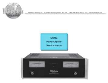
Technical DescriptionMcIntosh Laboratory, the company who introducedthe world’s first amplifier that could be called “HighFidelity”, has done it again. The McIntosh engineeringstaff has created a power amplifier without compromise, using the most advanced McIntosh circuit designconcepts.Figure 1314The MC152 has a continuous average power outputrating of 150 watts per channel and with a peak outputcurrent of 40 amperes; making this one of the mostadvanced amplifiers available today. The distortionlimits for the MC152 are no more than 0.005% atrated power output for all frequencies from 20Hz to20,000Hz. Typical performanceat mid frequencies is less than0.002%. The true distortion readings on the MC152 are so low, ittakes special measuring techniques to make accurate readings. The MC152 can deliver thebest possible performance fromany type of high quality loudspeaker system. Refer to figure13.Creating an amplifier withthis level of performance did notcome easily. Many months of design, testing and measuring wererequired. Extensive controlledlistening tests, the ultimate formof measuring, were made beforethe final design was accepted.Design PhilosophyThe design philosophy incorporated in the MC152 involvedseveral different techniques, allbased on sound scientific logic.Every stage of voltage or currentamplification must be as linear aspossible prior to the use of negative feedba
this manual. We want you to be as familiar as pos-sible with all the features and functions of your new McIntosh. The serial number, purchase date and McIntosh Dealer name are important to you for possible insurance claim or future service. The spaces below have been provided for you to record that information: