Transcription
Underground Installations of DWVPiping SystemsCopyright 2017 by American Society of Plumbing Engineers
Underground Installations ofDWV Piping Systems PIPE MATERIAL SELECTION CODES & STANDARDS REGIONAL SOIL CONDITIONS RECOGNIZING INSTALLATION CONCERNS USING AVAILABLE REFERENCES ADDRESSING FIELD CONDITION CHALLENGESCopyright 2017 by American Society of Plumbing Engineers
Underground InstallationRigid and Flexible materialsmust be installedusing very different methodsCopyright 2017 by American Society of Plumbing Engineers
Point of FailureRigid Systems: CISPLoaded to the point where theycrushFlexible Systems: ThermoplasticsStrength comes from soil aroundthe pipe 5% deflection is failure ASTM D 2321Copyright 2017 by American Society of Plumbing Engineers
Materials:CAST IRONPLASTICS SERVICE EXTRA HEAVY HUBLESSCopyright 2017 by American Society of Plumbing Engineers PVC ABS CPVC
Types of Cast Iron SystemsHub and SpigotService (SV)Extra Heavy (XH)HublessOnly available in one weightCommonly referred to as“No-Hub”Copyright 2017 by American Society of Plumbing Engineers
Cast Iron DimensionsThe dimensional standards for Cast Iron SoilPipe are unique to Soil PipeHubless, SV & XH each have slightly differentdimensions4” XH – OD 4.50”4” SV – OD 4.30”4” NH – OD 4.38”While dimensionally somewhat close to Sch40 Iron Pipe Size, NO type of Cast Iron Pipe isSch 40Copyright 2017 by American Society of Plumbing Engineers
Materials: Hub & Spigot Service Weight : UsuallyInstalled in “Normal”underground applications Extra Heavy : UsuallyInstalled in The “Tough”applications. Extreme earth & live load, &unstable soil conditions.Copyright 2017 by American Society of Plumbing Engineers
Materials: Hubless or No-HubHubless: TypicallyInstalled in aboveGround applicationsCopyright 2017 by American Society of Plumbing Engineers
Materials: PVC/ABSPVC/ABS: Installed inResidential andCommercialapplications above,and below gradewhere allowed byCodes.Copyright 2017 by American Society of Plumbing Engineers
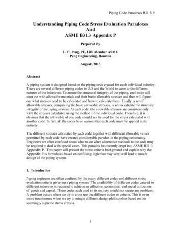
Incidentally:Solid Wall PVC vs. Cellular Foam CoreSolid WallCellular, or Foam CoreCopyright 2017 by American Society of Plumbing Engineers
PVC Schedule 80 for DWV ApplicationsOccasionally a designer will specify schedule 80 PVCpressure pipe meeting ASTM D 1785 for a DWV applicationin combination with schedule 40 PVC drainage fittings.Typically the application is underground and the designer isinterested in specifying a pipe that is more robust thanschedule 40 PVC.Copyright 2017 by American Society of Plumbing Engineers
Materials:CPVC: Installed inSpecial Wasteapplications above,and below gradeCPVC“Special Waste”Copyright 2017 by American Society of Plumbing Engineers
Materials:Glass: Installed in Special Wasteapplications above, and belowgrade. Should be encased inE.P.S. (expanded polystyrene) w/compacted select base & fill
Codes & Standards:UPC, IPC,NSPCASTMCast Iron Soil PipeInstitute (CISPI)ASTM A 74, ASTM A 888, ASTM D 2321, ASTM A 674, ASTM C 1277,ASTM C 564, ASTM C 1564UPC – CHAPTER 7IPC – CHAPTER 7NSPC – CHAPTER 11 CISPI – 301, CISPI – 310Copyright 2017 by American Society of Plumbing Engineers
Codes & Standards:ASTM StandardsASTM A 74, Standard specification for Hub & Spigot cast iron soil pipe & fittings forsanitary & storm drain, waste, & vent piping applications.ASTM A 888, Standard specification for Hubless cast iron soil pipe & fittings forsanitary & storm drain, waste, & vent piping applications.ASTM C 1277, Standard Specification for “Regular” or “Standard” Shielded CouplingsJoining Hubless Cast Iron Soil Pipe and Fittings.ASTM C 1540, Standard Specification for Heavy Duty Shielded Couplings JoiningHubless Cast Iron Soil Pipe and Fittings.ASTM C 564, Standard Specification for Rubber Gaskets Joining Hub & Spigot CastIron Soil Pipe and Fittings.ASTM D 2321, Standard practice for Underground Installation of Thermoplastic pipefor sewers & other gravity flow applications.ASTM A 674, Standard practice for Polyethylene encasement for Ductile, or Cast IronCopyright 2017 by American Society of Plumbing Engineerssoil pipe and fittings.
Codes & Standards:CISPI StandardsCISPI - 301, Standard specification for Hubless cast iron soil pipe & fittings forsanitary & storm drain, waste, & vent piping applications.CISPI - 310, Standard specification for coupling for use in connection with Hublesscast iron soil pipe & fittings for sanitary & storm drain, waste, & vent pipingapplications.Major Model CodesIPC, UPC:Chapter 7,Sanitary Drainage, 702.2 Underground DrainageNSPC: (Maryland, NJ)Chapter 11,Sanitary DrainageCopyright 2017 by American Society of Plumbing Engineers
Codes & Standards: ThermoplasticsRecommendations for Underground installation of Plastic Drainage PipePLASTIC DWV PIPE SHOULD ALWAYS BE BURIED IN STRICT ACCORDANCE WITH ASTM D2321Copyright 2017 by American Society of Plumbing Engineers1.A MINUMIUM WIDTH OF THE TRENCH SHOULD BE THE PIPE OD (OUTSIDE DIAMETER) PLUS16 INCHES OR THE PIPE OD TIMES 1.25 PLUS 12 INCHES. THIS WILL ALLOW ADUQUATEROOM FOR JOINING THE PIPE, SNAKING THE PIPE IN THE TRENCH TO ALLOW FOREXPANSION AND EXPANSION WHERE APPROPRIATE AND SPACE FOR BACKFILLING ANDCOMPACTION OF BACKFILL. THE SPACE BETWEEN THE PIPE AND TRENCH WALL MUST BEWIDER THAN THE COMPACTION EQUIPMENT USED TO COMPACT THE BACKFILL.2.PROVIDE A MINIMUM OF 4 INCHES OF FIRM, STABLE, AND UNIFORM BEDDING MATERIALIN THE TRENCH BOTTOM. IF ROCK OR UNYIELDING MATERIAL IS ENCOUNTERED, AMINIMUM OF 6 INCHES OF BEDDING SHALL BE USED. BLOCKING SHOULD NOT BE USED TOCHANGE PIPE GRADE OR TO INTERMITTENTLY SUPPORT PIPE OVER LOW SECTIONS IN THETRENCH.3.THE PIPE SHOULD BE SURROUNDED WITH AN AGGREGATE MATERIAL WHICH CAN BEWORKED AROUND THE SIDES OF THE PIPE. BACKFILLING SHOULD BE PERFORMED IN LAYERSOF 6 INCHES WITH EACH LAYER BEING SUFFICIENTLY COMPACTED TO 85% TO 95%COMPACTION.4.A MECHANICAL TAMPER IS RECOMMENDED FOR COMPACTING SAND AND GRAVEL. THESEMATERIALS CONTAIN FINE-GRAINS SUCH AS SAND AND CLAY. IF A TAMPER IS NOTAVAILABLE, COMPACTING SHOULD BE DONE BY HAND.5.THE TRENCH SHOULD BE COMPLETELY FILLED. THE BACKFILL SHOULD BE PLACED ANDSPREAD IN UNIFORM LAYERS TO PREVENT ANY UNFILLED SPACES OR VOIDS. LARGE ROCKS,STONES, FROZEN CLODS, OR OTHER LARGE DEBRIS SHOULD BE REMOVED. STONE BACKFILLSHALL PASS THROUGH AN 1-1/2” SIEVE. ROCK SIZE SHOULD BE APPROXIMATELY ONETENTH OF THE PIPE OUTSIDE DIAMETER. HEAVY TAMPERS OR ROLLING EQUIPMENTSHOULD ONLY BE USED TO CONSOLODATE FINAL BACKFILL.6.TO PREVENT DAMAGE TO THE PIPE AND DISTURBANCE TO PIPE EMBEDMENT, A MINIMUMDEPTH OF BACKFILL ABOVE THE PIPE SHOULD BE MAINTAINED. PROVIDE COVER (THAT ISTHE DEPTH OF BACKFILL ABOVE THE PIPE) OF AT LEAST 24 INCHES , OR ONE PIPE DIAMETER(WHICHEVER IS LARGER) FOR CLASS I EMBEDMENT, AND A COVER OF AT LEAST 36 INCHES,OR ONE PIPE DIAMETER (WHICHEVER IS LARGER) FOR Class II, III, AND IV EMBEDMENTBEFORE ALLOWING VEHICLES OR CONSTRUCTION EQUIPMENT TO TRAFFIC THE TRENCHSURFACE. PROVIDE AT LEAST 48 INCHES OF COVER BEFORE USING A HYDROHAMMER-TYPEFOR COMPACTION. PIPE SHOULD ALWAYS BE INSTALLED BELOW THE FROST LEVEL.TYPICALLY IT IS NOT ADVISEABLE TO ALLOW VEHICULAR TRAFFIC OR HEAVY CONSTRUCTIONEQUIPMENT TO TRAVERSE THE PIPE TRENCH.
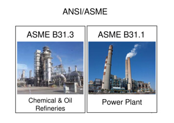
ASTM-D2321Soil type Classification – Soil classifications are grouped based on the typical soil stiffness when compacted. Thelower class number indicates a soil that generally provides the highest soil stiffness at any given percentage ofcompaction, and provides a given soil stiffness with the least compactive effort. Each higher-number soil classprovides successively less soil stiffness at a given percentage of compaction and requires greater compactiveeffort to provide a given level of soil stiffness.Soil Classes;Class I - Provides maximum stability and pipe support for a given percentage of compaction due to low content of sand and fines.With a minimum effort these materials can be installed at relatively high soil stiffness over a wide range of moisture contents. Inaddition, the high permeability of Class I materials may aid in the control of water, and these materials are often desirable forembedment in rock cuts where water is frequently encountered. However when ground-water flow is anticipated, considerationshould be given to the potential for migration of fines from adjacent materials into the open-graded Class I materials.Class II – When compacted provides a relatively high level of pipe support; however, open-graded groups may allow migration andsizes should be checked for compatibility with adjacent materials.Class III – Provides less support for a given percent of compaction than Cass I, or Class II materials. Higher levels of compactive effortis required and moisture content must be near optimum to minimize compactive effort and achieve the required percentcompaction. These materials provide reasonable levels of pipe support once proper percentage compaction is achieved.Class IV – Requires a geotechnical evaluation prior to use. Moisture content must be near optimum to minimize compactive effortand achieve the required percent compaction. Properly placed and compacted materials can provide reasonable levels of pipesupport; however, these materials may not be suitable under high fills, surface-applied wheel loads, or under high energy levelvibratory compactors and tampers. Do not use where water conditions in the trench may prevent proper placement andcompaction.Class V – Class V materials should be excluded from pipe-zone embedment.Copyright 2017 by American Society of Plumbing Engineers
Recommendations for Istallation and Use of Soils and Aggregates for Foundation and Pipe EmbedmentSoils ClassClass IClass IIWhere hydraulic gradient existscheck gradation to minimizemigration. Clean groups arewith geotextile filter media.suitable for use as a drainageSuitable for use as a drainage blanket and underdrian.blanket and under drain where Uniform fine sands (SP) withadjacent material is suitably more than%)5 passing through agraded or when used with a#100 sieve behave like silts andgeotextile filter fabric.should be treated like Class IIIsoils.Class IIIDo not use where waterconditions in trenchprevent properplacement andcompaction. Notrecommended for usewith pipes with stiffnessof 9 psi or less.Class IVClass VDifficult to achieve high-soilClass V materials shouldstiffness. Do not use where waterbe excluded from pipeconditions in trench prevent proper zone embedment.placement and compaction. Notrecommended for use with pipeswith stiffness of 9 psi or less.FoundationSuitable as foundation and forreplacing over-excavated andunstable trench bottom asrestricted above.Suitable as foundation and forreplacing over-excavated andunstable trench bottom asrestricted above. Install andcompact in 12 in. maximumlayersSuitable as foundationand for replacing overexcavated and unstabletrench bottom asrestricted above. Installand compact in 6 in.maximum layersSuitable as foundation and forN/Areplacing over-excavated trenchbottom for depths up to 12 in. asrestricted above. Use only whereuniform longitudinal support can bemaintained, as approved by theengineer. Install and compact in 6in. maximum layers.Pipe EmbedmentSuitable as restricted above.Work material under pipe toprovide unifrom haunchsupport.Suitable as restricted above.Work material under pipe toprovide unifrom haunchsupport.Suitable as restrictedabove. Difficult to placeand compact in thehaunch zoneSuitable as restricted above.N/ADifficult to place and compact in thehaunch zoneMinimumRecommendedPercent Compaction(Standard ProctorDensity)Suitable compaction typicallyis achieved by dumpedplacement (that is,uncompacted but worked intothe haunch zone to assurecomplete placement).85% for Sand & Clay/Silt. Placeand compact Gravel & Clay/Siltwith at least two passes ofcompaction equipment90%95%N/ARelative Compactive LowEffort Required toAchieve MinimumPercent CompactionModerateHighVery HighN/ACompaction Methods Vibration or ImpactVibration or ImpactImpactImpactN/ARequired MoistureControlNoneMaintain near optimumto minimize compactiveeffortMaintain near optimum to minimize N/Acompactive effortAcceptable and commonGenera lRecommenda tions where no mitigation isprobable or when combined& Res tri ctionsNoneCopyright 2017 by American Society of Plumbing Engineers
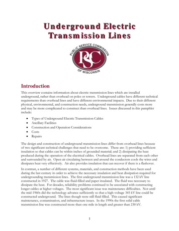
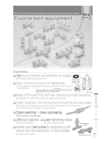
THERMOPLASTIC PIPE TRENCH CONSTRUCTIONFoundation: A foundation is necessary only when native soils areunstable, contains large rock, debris, or frozen clumps. For suchconditions the trench is over excavated and would be replacedwith suitable materials in compacted layers of a maximum depthof 6” until desired trench depth is attained.Embedment: this zone is the most important in terms of pipeperformance. It is divided into the following sub-zones:Bedding: Typically four to six inches of supportive, compactedmaterial. This zone provides an even support for the pipe andbrings it to grade.Haunching: Extends from the bottom of the pipe to the centerlineof the pipe (springline). It provides the most resistance to pipedeflection. Specifying proper materials and compaction are mostimportant to this zone.Initial Backfill: extends from the springline to a point above the topof the pipe. This zone provides some pipe support and helps toprevent damage to the pipe during placement of the final backfill.The cover extends from the top of the pipe to the top of the initialbackfill. The depth of cover should be as much as necessary toprotect the pipe during placement of final backfill. 6” is commondepth of cover.Final Backfill: this zone extends from top of the initial backfill to thetop of the trench. This zone has little influence on pipeperformance, but can be important to the integrity of roads andstructures.Copyright 2017 by American Society of Plumbing Engineers
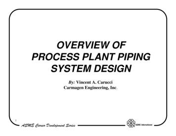
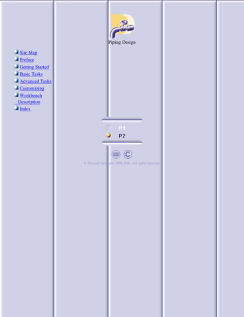
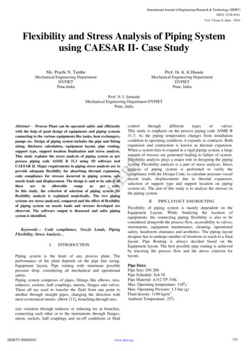
Unfortunately, these pictures are indicativeof typical burial procedures used in the field.Copyright
ASTM C 564, Standard Specification for Rubber Gaskets Joining Hub & Spigot Cast Iron Soil Pipe and Fittings. ASTM D 2321, Standard practice for Underground Installation of Thermoplastic pipe for sewers & other gravity flow applications. ASTM A 674, Standard practice for Polyethylene encasement for Ductile, or Cast Iron soil pipe and fittings.