Transcription
OVERVIEW OF VACUUM DRYING METHODSAND FACTORS AFFECTING THE QUANTITYOF RESIDUAL WATER AFTER DRYING –PUBLIC VERSIONPrepared forU.S. Nuclear Regulatory CommissionContract No. NRC–02–07–006Prepared byL. MillerD. BasuK. DasT. MintzR. PabalanG. WalterCenter for Nuclear Waste Regulatory AnalysesSan Antonio, TexasGreg ObersonU.S. Nuclear Regulatory CommissionOffice of Nuclear Regulatory ResearchJuly 2013
CONTENTSSectionPageFIGURES .iiiTABLES . ivEXECUTIVE SUMMARY . vACKNOWLEDGMENTS .vii1INTRODUCTION . 1-11.1Background . 1-11.2Purpose and Scope . 1-32TYPICAL INDUSTRY DRYING EQUIPMENT AND PROCEDURES. 2-12.1Approach . 2-12.2Equipment Used for Vacuum Drying . 2-12.2.1 General Setup. 2-12.2.2 Pumps . 2-12.2.3 Water Trap . 2-22.2.4 Piping, Hoses, and Connections. 2-22.2.5 Valves . 2-22.2.6 Gauges, Sensors, and Transducers . 2-22.3Procedures . 2-32.3.1 Setup and Checkout . 2-32.3.2 Initial Pump Down and Blow Down and Vacuum. 2-32.3.3 Vacuum Drying . 2-42.4Test Plan Considerations for Vacuum Drying System and OperationalProcedures . 2-103FUEL ASSEMBLY AND CANISTER CHARACTERISTICS . 3-13.1Test Plan Considerations for Fuel Assembly Designs. 3-13.2Test Plan Considerations for Canister Designs . 3-33.3Test Plan Considerations for Fuel Heat Load. 3-43.4Test Plan Considerations for Damaged Fuel Rods . 3-44CONCEPTS FOR MEASURING THE QUANTITY OF RESIDUAL WATERAFTER DRYING . 4-14.1Measurement Capabilities Needed . 4-14.2Potential Measurement Techniques . 4-24.2.1 Gas Water Content Measurement . 4-44.2.2 Temperature Measurement . 4-44.2.3 Vacuum Pressure Measurement . 4-54.2.4 Flow Measurement . 4-55SUMMARY . 5-16REFERENCES . 6-1ii
FIGURESFigurePage1-11-2Pressure-Temperature Phase Diagram for Pure Water . 1-2Calculated Temperature and Amount of Solid Ice (Following Red Arrow) ThatForms When Pressure Is Lowered Adiabatically in a System Contaoning 1L [0.26 gal]of Pure Water . 1-23-13-23-33-4Typical PWR 17x17 Fuel Assembly . 3-2GE14 Fuel Assembly . 3-3Transnuclear 24PT Dry Storage Canister . 3-4Plot of PWR Spent Fuel Heat Generation Rates as a Function of Cooling Time atVarious Burnups for Specific Power 40 kW/kgU. Plot Made from Data in Table 7 of NRCRegulatory Guide 3.54, “Spent Fuel Heat Generation in an Independent Spent FuelStorage Installation” . 3-5Schematic Showing the Flow and Phase Change of Trapped Water During Drying . 3-63-54-1Conceptual Illustration of the Pressure, Dew Point, and Water/Ice TemperatureResponse Indicating Complete Removal of Free Water . 4-2iii
TABLESTablePage4-1Possible Measurement Techniques and Considerations . 4-35-1Recommendations for Factors to Consider in Test Plan . 5-1iv
EXECUTIVE SUMMARYAfter pool loading, spent nuclear fuel canisters may be vacuum dried prior to the storageperiod, using a mechanical pumping system to remove the water. Water remaining in thecanister could cause corrosion of the fuel cladding and internal structures or may create aflammable environment within the canister if radiolysis creates free oxygen and hydrogen.NRC provides only general guidance to licensees concerning the implementation of vacuumdrying. In particular, NUREG–1536, “Standard Review Plan for Dry Cask Storage Systems,”(NRC, 2010) states that NRC staff accepts vacuum drying methods comparable to thoserecommended in Pacific Northwest National Laboratory Report PNL–6365, “Evaluation of CoverGas Impurities and their Effects on the Dry Storage of LWR Spent Fuel” (PNNL, 1987), whichspecifies less than 0.25 volume percent oxidizing gasses in the canister. When vacuum dryingis implemented, licensees have a technical specification directing that the canister be evacuatedto below a certain pressure with demonstration that the pressure will remain stable for a periodof time after the canister is isolated from the pumping system.There have been no experimental tests to measure the quantity of residual water that mayremain in the canister following vacuum drying. If vacuum drying proceeds too quickly, it ispossible that ice could form in the canister, particularly at locations where water is entrapped inconfined spaces. If ice forms, the system pressure may meet the technical specification even ifwater is still present in the canister. To provide additional confidence that the criterionrecommended in NUREG–1536 is appropriate, NRC initiated a research activity with theCenter for Nuclear Waste Regulatory Analyses (CNWRA ) to develop a conceptual test plan formeasuring the quantity of unbound residual water remaining in a canister following vacuumdrying. This activity consists of the preparation of two technical letter reports. The first is thepresent report, which describes typical vacuum drying systems and operational procedures. Italso reviews canister and fuel assembly designs to determine locations or conditions that couldbe susceptible for retaining water and should be evaluated in the test plan. The second reportwill be the conceptual test plan itself.Information on current industry drying practices was gathered by reviewing safety analysisreports, vacuum drying operational procedures, and design drawings. Further, visits wereconducted to vendors to observe the setup and operation of their vacuum drying systems and todiscuss field experience with their staff. In general, it was found that drying systems andprocedures are similar throughout the industry. Most of the equipment used in the dryingsystems, including pumps, valves, hoses, and gauges, are available off the shelf. Provided thatit is appropriate for its intended function, the selection of equipment should not affect thequantity of residual water remaining in the canister following vacuum drying. Therefore,equipment or system design variations are not recommended to evaluate in the test plan. Toprevent ice formation, vacuum drying is typically performed in a stepwise manner, graduallydecreasing the pressure to certain hold points, at which the canister is isolated from thepumping system for a period of time to confirm that stable pressure readings are obtained. Thenumber of hold points and the final canister pressure could affect the quantity of residual water ifthey are such that ice formation is not detected. It is thus recommended to evaluate theseoperational parameters in the test plan.Fuel assembly and canister designs were reviewed to identify locations where water could betrapped or difficult to remove during drying. One important case is that of a rod with breachedcladding that becomes waterlogged in the core. If the hole or crack in the cladding has limitedopening area, it could take a long time for water to flow out during drying or the hole could icev
over, completely blocking the exit path. The flow rate of water out of the fuel rod or the potentialfor icing will depend upon the size and location of holes along the length of the cladding. Otherlocations identified include the dashpot region of the guide thimble tube for pressurized waterreactor assemblies and the water rod for boiling water reactor assemblies, both of which arehollow tubes into which water can flow, but are closed at the bottom end. Lastly, water could bedifficult to remove from creviced regions around geometrically complex assembly hardware,such as grids, nozzles, and tie rods. For the canister itself, the most likely location for retainingwater is thought to be on the flat surfaces of spacer disks. It is recommended to evaluate thepotential for water entrapment in all of these locations in the test plan. Ice formation duringdrying should be more likely for fuel with a lower decay heat load, thus it is also recommendedto consider the heat load as a variable in the test plan.Finally, potential methods that may be employed in tests to measure the quantity of residualwater remaining in the canister following vacuum drying were reviewed. A number of thesewere identified from similar applications in the pharmaceutical industry. In addition to massbalance, certain methods are based on measuring changes in the temperature, pressure, ordew point within the canister, while other techniques involve mass flow or visual observation.Most equipment that would be needed for such measurements is available off the shelf.ReferencesNRC. NUREG–1536, “Standard Review Plan for Spent Fuel Dry Storage Systems at a GeneralLicense Facility.” Rev. 1. Washington, DC: U.S. Nuclear Regulatory Commission. July 2010.ADAMS ML101040620.PNNL. “Evaluation of Cover Gas Impurities and Their Effects on the Dry Storage of LWRSpent Fuel.” PNL–6365. Richland, Washington: Pacific Northwest National Laboratory.November 1987.vi
ACKNOWLEDGMENTSThis report was prepared to document work performed by the Center for Nuclear WasteRegulatory Analyses (CNWRA ) for the U.S. Nuclear Regulatory Commission (NRC) underContract No. NRC–02–007–006. The studies and analyses reported here were performed onbehalf of the NRC Office of Nuclear Regulatory Research, Division of Engineering. The reportis an independent product of CNWRA and does not necessarily reflect the view or regulatoryposition of NRC.The authors thank Bob Einziger, Matt Gordon of NRC, as well as Lane Howard for technicalreview, and Yiming Pan and David Pickett for programmatic review. The authors also thankBeverly Street and Lee Selvey for administrative support in report preparation.QUALITY OF DATA, ANALYSES, AND CODE DEVELOPMENTDATA: All CNWRA-generated original data contained in this report meet the quality assurancerequirements described in the Geosciences and Engineering Division Quality AssuranceManual. Sources for other data should be consulted for determining the level of quality forthose data.ANALYSES AND CODES: No scientific or engineering software was used in the analysescontained in this report.vii
1 INTRODUCTION1.1BackgroundIn the United States, spent nuclear fuel (SNF) is maintained in dry storage at a numberof operating and decommissioned reactor sites and certain other facilities licensed by theU.S. Nuclear Regulatory Commission (NRC). In the dry storage concept, SNF is movedfrom the spent fuel pool to metal canister or cask systems. NRC regulates the dry storageof SNF under Title 10 of the Code of Federal Regulations (10 CFR), Part 72 “LicensingRequirements for the Independent Storage of Spent Nuclear Fuel, High-Level RadioactiveWaste, and Reactor-Related Greater than Class C Waste.” The provisions of 10 CFR Part 72are intended, in part, to prevent gross degradation of fuel cladding and ensure the confinementof radioactive material during storage and transportation. Therefore, after being transferredfrom the spent fuel pool, water is removed from the canisters to create a dry environment.Water remaining in the canister could cause corrosion of the fuel cladding and internalstructures or may create a flammable environment within the canister if radiolysis creates freeoxygen and hydrogen (ASTM International, 2008).One method that licensees use to remove water from canisters is vacuum drying with amechanical pumping system. NRC provides only general guidance to licensees concerning theimplementation of vacuum drying. In particular, NUREG–1536, “Standard Review Plan for DryCask Storage Systems,” (NRC, 2010) states that NRC staff accepts vacuum drying methodscomparable to those recommended in Pacific Northwest National Laboratory Report PNL–6365,“Evaluation of Cover Gas Impurities and their Effects on the Dry Storage of LWR Spent Fuel,”(PNNL, 1987). PNL–6365 recommends a maximum quantity of 1 mol of oxidizing gases(O2, CO2, and CO) in a canister with a total gas volume of 7 m3 [247 ft3] at a pressure of0.15 MPa [1.5 atm], corresponding to a concentration of about 0.25 percent. In practice,licensees have a technical specification directing that the canister be evacuated to a pressurebetween 3 and 10 torr [400 Pa and 1.33 kPa], with demonstration that the pressure will remainstable for a number of minutes after the canister is isolated from the pumping system.The recommendation in PNL–6365 is based on thermodynamic calculations of equilibrium gaspressures, not on physical measurements made from evacuated canisters. There have been noexperimental tests to determine the quantity of residual water that may remain in the canisterfollowing drying to this level. Recently, NRC has undertaken a review of its regulatoryframework for extended storage and transportation of SNF (NRC, 2012b). As part of thisreview, NRC identified technical information gaps and research needs that warrant furtherconsideration to ensure that SNF continues to be stored safely. It was determined that a testprogram to measure the quantity of residual water following vacuum drying could increaseconfidence that the NRC guidance in NUREG–1536 is appropriate.A particular concern for vacuum drying is the formation of ice within the canister as the pressuredecreases. Lowering the pressure below the saturation vapor pressure of liquid water willcause vaporization of the liquid, as illustrated in Figure 1-1. Vaporization of liquid water takesenergy from the liquid water. If the pressure is decreased too rapidly, so much heat can beremoved that the remaining liquid could freeze. Figure 1-2 illustrates the calculated temperaturedrop when the pressure of a system containing 1 L [0.26 gal] of water is decreasedadiabatically. The calculation was done using OLIAnalyzer Studio Version 3.2 (OLISystems,Inc., 2012). As shown in the figure, liquid water is fully transformed to ice when total pressure1-1
Figure 1-1. Pressure-Temperature Phase Diagram for Pure Water. Stable PhaseBoundaries Are Shown by Solid Lines and a Metastable Phase Boundary Is Indicated byDashed Line.Figure 1-2. Calculated Temperature and Amount of Solid Ice (Following Red Arrow) ThatForms When Pressure Is Lowered Adiabatically in a System Containing 1 L [0.26 gal] ofPure Water1-2
is decreased below 4.58 torr [610 Pa]. The potential for ice formation may be greatest inregions of the fuel assembly or canister where water is difficult to remove because it is trappedin confined spaces.1.2Purpose and ScopeNRC initiated a research activity with the Center for Nuclear Waste Regulatory Analyses(CNWRA ) to develop a conceptual test plan for measuring the quantity of residual waterremaining in a canister following vacuum drying to the criterion referenced in NUREG–1536.While residual water may be considered as unbound or bound (i.e., physi- or chemisorbed), thefocus of this test plan is only the unbound water. This activity consists of the preparation of twotechnical letter reports. The first is the present report, which describes current industry dryingpractices and capabilities. It also reviews canister and fuel assembly designs to determinedesign features or characteristics that could affect the quantity of residual water after drying.Based on this information, recommendations are made for parameters to evaluate in the testplan. The second report will be the conceptual test plan itself. The contents of this report areas follows: Section 2 describes the setup and operation of typical industry vacuum drying systems. Section 3 describes the characteristics of fuel assemblies and canisters that may affectthe quantity of residual water after drying. Section 4 describes measurement techniques and equipment that may be employed tomeasure the quantity of residual water. Section 5 provides a summary of the report.1-3
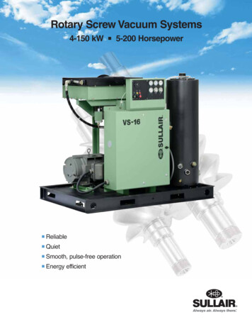
2 TYPICAL INDUSTRY DRYING EQUIPMENT AND PROCEDURES2.1ApproachThe development of the test plan for measuring the quantity of residual water after vacuumdrying will require thorough understanding of equipment and procedures used in the industry.To gather such information, industry vacuum drying procedures were reviewed and visits wereconducted to vendor facilities to observe the equipment and its operation in person, as well asto discuss field experience with their staff.2.2Equipment Used for Vacuum DryingThe equipment used for vacuum drying is relatively similar throughout the industry. Thefollowing subsections provide general descriptions of the main parts of vacuum drying systems.2.2.1General SetupA typical vacuum drying system consists of vacuum pumps, a water trap, piping and hoses,valves, and a suite of pressure gauges, with the pumps and water trap tank being mounted on arolling cart for ease of transport. The vacuum pump is connected to steel piping via flexiblevacuum tubing, which allows for easier installation and connections. The water trap tank isconnected in line with the steel piping, but valves are installed that allow this tank to be removedfrom the flow path when the system is sufficiently dry. Analog pressure gauges are mounted tothe steel piping around eye level to the operator. These gauges are used to aid the operator inthe blowdown and backfilling processes.Flexible vacuum hose is used for the main lines running from the cart to the canister. Theselines must be flexible to accommodate the various setup requirements seen during differentdrying campaigns. One of these vacuum hoses is connected directly to the canister siphon port.This siphon port connects to a tube that runs to the bottom of the canister and is used to removethe bulk water from the canister in preparation for vacuum drying. The other vacuum hoseconnects to stainless steel piping that is connected directly to the canister vent port. This pipingis called the riser manifold or tree, and contains connections for the main pressure sensors usedduring drying. These pressure sensors are placed close to the canister vacuum port, whichopens to the top of the canister, in an effort to obtain accurate measurements of the internalpressure.2.2.2PumpsCommercially-available, off-the-shelf pumps are generally used for vacuum drying. A typicalmain pump is a Leybold Sogevac SV 100, which is a rotary vane pump with the ability to reachpressures around 0.5 torr [67 Pa]. In addition to the main vacuum pump, a roots blower, whichis a positive displacement air pump, may be used to increase the pumping speed and efficiencyin the lower pressure ranges. The roots blower is mounted to the inlet side of the vacuum pumpand uses positive displacement of air to increase the air pressure at the inlet of the vacuumpump, thus increasing the vacuum pump efficiency. A typical roots blower is a Ruvac WA 251.2-1
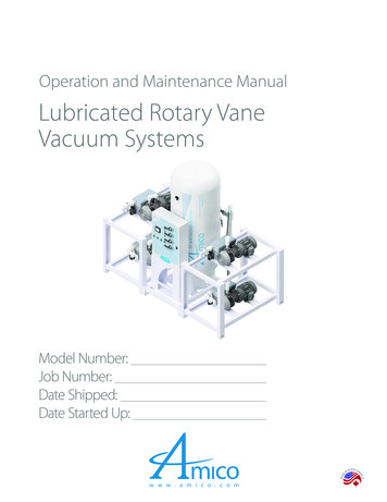
2.2.3Water TrapIn a vacuum drying system, the water trap tank is used as a means of protecting the vacuumpumps from damage. Rotary vane vacuum pumps use the compression of fluid to force air fromthe inlet of the pump to the outlet. If fluids that are considered incompressible, like water, enterthis type of pump the pump internals will fail and the pump will need to be replaced or repaired.Early in the vacuum process, water left after blow down enters the vacuum lines and can workits way toward the vacuum pump. During this time the water trap tank is valved into the vacuumpath and the air-water mixture in the vacuum lines is routed through the inlet of the water traptank. Liquid water is deposited in the tank while allowing the gasses to continue through theexhaust port and on to the vacuum pump. When no visible water droplets are apparent in thelines, this tank is valved out of the vacuum system. The removal of the tank from the vacuumsystem shortens the vacuum path, increasing the pumping efficiency. These water trap tanksusually have some form of sight glass to give an indication of when the water in the tank needsto be drained.2.2.4Piping, Hoses, and ConnectionsThe piping on the vacuum cart and the vacuum tree or manifold is constructed of stainless steeland the pipe is connected via Klein Flange/Quick Flange (KF/QF) style flanged connections.The lines running from the vacuum cart to the vacuum manifold and siphon port are hightemperature reinforced vacuum hoses connected via barbed fittings and hose clamps. Theseflexible hoses are required due to the varying configurations used at different vacuum dryinglocations. In addition, these hoses are used to connect the vacuum pump and the water traptank to the rest of the piping. These hoses are typically transparent to aid in the visualconfirmation of water removal. The vacuum tree and siphon port lines are connected to the ventport and siphon port of the canister with straight pipe nipples and a KF/QF fitting. Thisconnection is used for all but the final vacuum step, in which the pipe nipples are replaced withquick disconnect couplings that will stay with the canister through the rest of the storage.2.2.5ValvesMost valving in the systems surveyed consisted of manually actuated 90 degree ball valves.The only dissimilar valve is the vacuum pump inlet valve, which is a throttling valve used tocontrol the pump down speed. The throttling valve is required to avoid depressurizing thesystem too quickly and forming ice in the lines or the chamber.2.2.6Gauges, Sensors, and TransducersThe canister pressure is monitored during the drying process and at the final hold pressure tomeet the technical specification. Digital vacuum sensors can be mounted on the vacuummanifold for the canister presser measurements. A Pirani gauge may be used for measuringthe higher pressures during operation and an absolute pressure transducer for precisionmeasurement of the lower pressures. The gauges are usually positioned as close to the ventport opening of the canister as possible in order to reduce the pressure drop seen by thegauges and provide a more accurate reading of the canisters internal pressure.Additional pressure/vacuum gauges may be incorporated on the vacuum drying cart to aid theoperator in activities such as performing blow downs or backfilling with dry helium. These maynot be calibrated because they are not used for the technical specification measurement.2-2
2.3ProceduresThe procedures used for vacuum drying also seem to be similar among various vendors, withthe general concept to decrease pressure in a slow or step-wise manner to prevent iceformation by providing time for the system to equilibrate. The following subsections provide ageneral description of the vacuum drying process.2.3.1Setup and CheckoutIn this step, the equipment is pre-staged for the actual operation, all the pumps are warmed upand ready, and a system pull down test is performed. In the system pull down test, a vacuum ispulled on all the hoses and piping of the system in an effort to detect any leaks that may bepresent in the flanges, the hose connections, or in the actual hoses and pipes. If any leaks aredetected they are promptly repaired and the system is rechecked. This sequence is repeateduntil the cask loading supervisor or system operator is satisfied that the system is airtight.Some good practices for the vacuum drying setup include Run the vacuum hoses downhill from the siphon and vent ports to help drain water fromthe lines and decrease the chance of freezing water in the lines. Check and replace the seals on the KF/QF connections often. Over time the seals inthese connections will compress. The compression of these seals increases the chanceof air in leakage from these connections. All vacuum steps prior to the final pull should use straight pipe nipples at the vent andsiphon ports, not the quick disconnect (QD) couplings. The QD couplings cause anorifice type effect which can lead to icing and incorrect pressure readings. Plastic hoses and most thread sealants will off-gas under a vacuum, so use hosesand sealants that have low off-gassing, and pull a vacuum on the system a few timesbefore use.2.3.2Initial Pump Down and Blow Down and VacuumIn this step, a self-priming centrifugal pump is connected to the siphon port of the canister, andthe bulk water is pumped out until air starts to enter the lines. At this point the pump isdisconnected and the canister is hooked up to the vacuum drying system using straight pipenipples to increase air and water flow. The canister is pressurized with dry helium, then anexhaust valve, which is hooked to the siphon port, is opened and the pressure is allowed to dropto a specified point. The exhaust air and water is directed into the water trap tank which passesthe air and water through a drain valve. This blow down process is repeated until a minimumamount of water is observed in the siphon hose. At this point the initial pump down and blowdown of bulk water is complete.During the initial vacuum pull down steps, described in the next section, the water trap tank iskept in line with the vacuum system. The water trap tank separates the water from the air,capturing the water in the tank and allowing the air, which is now free of water drops, to proceedto the vacuum pump. This process prevents any large water particles from entering into, and2-3
damaging the vacuum pumps. When no visible water is present in the lines, this water trap tankis valved out of the vacuum system.2.3.3Vacuum DryingVacuum drying is generally performed in a step-wise manner, decreasing the pressure to aseries of predetermined hold points prior to reaching the final pressure. At each step, thecanister is isolated from the pump and the pressure is monitored for a specified period of time.The canister pressure will rise as water and other volatiles evaporate. If the pressure increasesto exceed a certain value during the hold time, the step may be repeated until a stable pressureis obtained. The numbers of hold points vary by vendor, but three to seven may be typical. Thefinal pressure to which the canister must be evacuated is specified in the technical specification,usually in the range of 3 to 10 torr [400 Pa to 1.33 kPa], with demonstration that the canister willnot exceed that pressure after being isolated from the pumping system for up to 30 minutes.Operational procedures may direct that the canister should be pumped to an even lowerpressure, accounting for uncertainties in the accuracy of the pressure gauges.After the final pressure is reached, the canister is given an initial helium backfill to slightly aboveambient pressure and the straight pipe nipples are replaced with QD couplings. This positivepressurization ensures that no moist air enters the canister while changing to the QD fittings.The canister is again evacuated to the technical specification pressure, after which it is given afinal helium backfill to several pounds per square inch. Typical times to dry a canister are in therange of 12 to 48 hours, depending on the characteristics of the canister and fuel. The processof drying tends to
comparable to those recommended in Pacific Northwest National Laboratory Report PNL-6365, "Evaluation of Cover Gas Impurities and their Effects on the Dry Storage of LWR Spent Fuel," (PNNL, 1987). PNL-6365 recommends a maximum quantity of 1 mol of oxidizing gases (O2, CO2, and CO) in a canister with a total gas volume of 7 m