Transcription
Basic ElectronicsFlip-FlopsFlip-FlopsSyllabus: Flip-Flops: Introduction to Flip-Flops, NAND Gate Latch/ NOR Gate Latch, RS Flip-Flop,Gated Flip-Flops: Clocked RS Flip-Flop.(5 Hours)Introduction to Flip-FlopsDigital circuits are classified into two types – Combinational circuits and Sequentialcircuits. Combinational circuits are the circuits in which the output depends on the presentinputs only. Sequential circuits are the circuits in which the output depends on the presentinput as well as the previous state of the system. The sequential circuits have memory. A flipflop is the basic element of all sequential systems.Flip-FlopA flip-flop is an electronic circuit which has memory. It is a bistable digital circuit, i.e.,its outputs have two stable states: logic 1 and logic 0. It is the basic element of all sequentialsystems.Difference between Latches and Flip-FlopsLatches and flip-flops are the basic building blocks of the most sequential circuits. Themain difference between latches and flip-flops is the method used for changing their state.Latches are controlled by an enable signal and they are level triggered, whereas, flip-flopsare controlled by a clock signal and they are edge triggered.Table 1 Differences between latches and flip-flopsLatchesFlip-FlopsLatches are controlled by an enable signalFlip-flops are controlled by a clock signalLatches are positive or negative leveltriggered, i.e., the output changes wheneverthe enable is 1 (for positive level-triggered)or 0 (for negative level-triggered)Flip-flops are positive or negative edgetriggered, i.e., the output changes wheneverthe clock changes from 0 to 1 (for positiveedge-triggered) or 1 to 0 (for negative edgetriggered)Latches are building blocks of sequential Flip-flops are also building blocks ofcircuits and are built from basic gatessequential circuits and are built from latchesA latch continuously checks its inputs and A flip-flop continuously checks its inputschanges its output whenever the enable is and changes its output only at timesHIGHdetermined by the clock signalThe operation of a latch is faster as they do Flip-flops are comparatively slower as theynot have to wait for clock signalhave to wait for clock signalTable 1 summarizes the differences between latches and flip-flops.Shrishail Bhat, Dept. of ECE, AITM Bhatkal1
Flip-FlopsBasic ElectronicsBasic Bistable ElementFig. 1 Basic bistable elementFig. 1 shows a basic bistable element. It has two inputs and two outputs as shown. Theoutput of one NOT gate is connected to the input of the other. In this case, the outputs 𝑄 and𝑄̅ will have a stable value complementary to each other, but cannot be controlled. To controlthe bistable element, we use latches.NAND Gate LatchA NAND gate latch is formed by cross connecting two NAND gates as shown inFig. 2.Fig. 2 NAND gate latchOperationThe inputs are 𝑅̅ and 𝑆̅. Hence there are four conditions:i.̅ ̅If 𝑹𝑺 𝟏Let the previous state output be 𝑄 0 (𝑄̅ 1). The inputs to the gate 1 are (1,1).So its output is 𝑄 0. The inputs to the gate 2 are (0,1). So its output is 𝑄̅ 1.(The output does not change).Let the previous state output be 𝑄 1 (𝑄̅ 0). The inputs to the gate 1 are (1,0).So its output is 𝑄 1. The inputs to the gate 2 are (1,1). So its output is 𝑄̅ 0.(The output does not change).That is, if 𝑅̅ 𝑆̅ 1, there is no change in the output.2Shrishail Bhat, Dept. of ECE, AITM Bhatkal
Basic ElectronicsFlip-Flops̅ 𝟎̅ 𝟏, 𝑺If 𝑹ii.Let the previous state output be 𝑄 0 (𝑄̅ 1). The inputs to the gate 1 are (0,1).So its output is 𝑄 1. The inputs to the gate 2 are (1,1). So its output is 𝑄̅ 0.Let the previous state output be 𝑄 1 (𝑄̅ 0). The inputs to the gate 1 are (0,0).So its output is 𝑄 1. The inputs to the gate 2 are (1,1). So its output is 𝑄̅ 0.That is, if 𝑅̅ 1, 𝑆̅ 0, the output is set (𝑄 1).̅ 𝟏̅ 𝟎, 𝑺If 𝑹iii.Let the previous state output be 𝑄 0 (𝑄̅ 1). The inputs to the gate 1 are (1,1).So its output is 𝑄 0. The inputs to the gate 2 are (0,0). So its output is 𝑄̅ 1.Let the previous state output be 𝑄 1 (𝑄̅ 0). The inputs to the gate 2 are (1,0).So its output is 𝑄̅ 1. The inputs to the gate 1 are (1,1). So its output is 𝑄 0.That is, if 𝑅̅ 0, 𝑆̅ 1, the output is reset (𝑄 0).̅ 𝟎̅ 𝑺If 𝑹iv.Let the previous state output be 𝑄 0 (𝑄̅ 1). The inputs to the gate 1 are (0,1).So its output is 𝑄 1. The inputs to the gate 2 are (1,0). So its output is 𝑄̅ 1.Here 𝑄 1 and 𝑄̅ 1, which is not possible. So the output is not valid.Let the previous state output be 𝑄 1 (𝑄̅ 0). The inputs to the gate 1 are (0,0).So its output is 𝑄 1. The inputs to the gate 2 are (1,0). So its output is 𝑄̅ 1.Again 𝑄 1 and 𝑄̅ 1, which is not possible. So the output is not valid.That is, if 𝑅̅ 𝑆̅ 0, the output is not valid. Hence this is forbidden.Considering all the four cases, the truth table is written as below.Truth Table:̅𝑹̅𝑺𝑸𝒏𝑸𝒏 𝟏State11110101No egal)̅𝑹̅𝑺𝑸𝒏 𝟏State11𝑄𝑛No change101Set010Reset00?Forbidden(Illegal)𝑄𝑛 - Present state output𝑄𝑛 1 - Next state outputNOR Gate LatchA NOR gate latch is formed by cross connecting two NOR gates as shown inFig. 3.Shrishail Bhat, Dept. of ECE, AITM Bhatkal3
Flip-FlopsBasic ElectronicsFig. 3 NOR gate latchOperationThe inputs are 𝑅 and 𝑆. Hence there are four conditions:i.If 𝑹 𝑺 𝟎Let the previous state output be 𝑄 0 (𝑄̅ 1). The inputs to the gate 1 are (0,1).So its output is 𝑄 0. The inputs to the gate 2 are (0,0). So its output is 𝑄̅ 1.Let the previous state output be 𝑄 1 (𝑄̅ 0). The inputs to the gate 1 are (0,0).So its output is 𝑄 1. The inputs to the gate 2 are (1,0). So its output is 𝑄̅ 0.That is, if 𝑅 𝑆 0, there is no change in the output.ii.If 𝑹 𝟎, 𝑺 𝟏Let the previous state output be 𝑄 0 (𝑄̅ 1). The inputs to the gate 2 are (0,1).So its output is 𝑄̅ 0. The inputs to the gate 1 are (0,0). So its output is 𝑄 1.Let the previous state output be 𝑄 1 (𝑄̅ 0). The inputs to the gate 1 are (0,0).So its output is 𝑄 1. The inputs to the gate 2 are (1,1). So its output is 𝑄̅ 0.That is, if 𝑅 0, 𝑆 1, the output is set (𝑄 1).iii.If 𝑹 𝟏, 𝑺 𝟎Let the previous state output be 𝑄 0 (𝑄̅ 1). The inputs to the gate 1 are (1,1).So its output is 𝑄 0. The inputs to the gate 2 are (0,0). So its output is 𝑄̅ 1.Let the previous state output be 𝑄 1 (𝑄̅ 0). The inputs to the gate 1 are (1,0).So its output is 𝑄 0. The inputs to the gate 2 are (0,0). So its output is 𝑄̅ 1.That is, if 𝑅 1, 𝑆 0, the output is reset (𝑄 0).iv.If 𝑹 𝑺 𝟏Let the previous state output be 𝑄 0 (𝑄̅ 1). The inputs to the gate 1 are (1,1).So its output is 𝑄 0. The inputs to the gate 2 are (0,1). So its output is 𝑄̅ 0.Here 𝑄 0 and 𝑄̅ 0, which is not possible. So the output is not valid.Let the previous state output be 𝑄 1 (𝑄̅ 0). The inputs to the gate 1 are (1,0).So its output is 𝑄 0. The inputs to the gate 2 are (0,1). So its output is 𝑄̅ 0.Again 𝑄 0 and 𝑄̅ 0, which is not possible. So the output is not valid.That is, if 𝑅 𝑆 1, the output is not valid. Hence this is forbidden.4Shrishail Bhat, Dept. of ECE, AITM Bhatkal
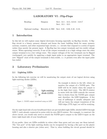
Basic ElectronicsFlip-FlopsConsidering all the four cases, the truth table is written as below.Truth Table:𝑹𝑺𝑸𝒏𝑸𝒏 𝟏State00000101No egal)𝑹𝑺𝑸𝒏 𝟏State00𝑄𝑛No change011Set100Reset11?Forbidden(Illegal)𝑄𝑛 - Present state output𝑄𝑛 1 - Next state outputRS Flip-FlopIn RS flip-flop, the inputs are 𝑅 and 𝑆. We want to achieve 𝑄 0 (Reset) when 𝑅 1and 𝑄 1 (Set) when 𝑆 1. Fig. 4 shows the logic diagram and symbol of an RS flip-flop(latch).Fig. 4 RS Flip-Flop (Latch)OperationThe inputs are 𝑅 and 𝑆. NAND gates 1 and 2 act as inverters and produce 𝑆̅ and 𝑅̅respectively which are the inputs to gates 3 and 4. The gates 3 and 4 form a NAND gate latch.The operation can be analyzed for the four conditions:i.If 𝑹 𝑺 𝟎If 𝑅 𝑆 0, then 𝑅̅ 𝑆̅ 1.Let the previous state output be 𝑄 0 (𝑄̅ 1). The inputs to the gate 3 are (1,1).So its output is 𝑄 0. The inputs to the gate 4 are (0,1). So its output is 𝑄̅ 1.(The output does not change).Shrishail Bhat, Dept. of ECE, AITM Bhatkal5
Flip-FlopsBasic ElectronicsLet the previous state output be 𝑄 1 (𝑄̅ 0). The inputs to the gate 3 are (1,0).So its output is 𝑄 1. The inputs to the gate 4 are (1,1). So its output is 𝑄̅ 0.(The output does not change).That is, if 𝑅 𝑆 0, there is no change in the output.ii.If 𝑹 𝟎, 𝑺 𝟏If 𝑅 0, 𝑆 1, then 𝑅̅ 1, 𝑆̅ 0.Let the previous state output be 𝑄 0 (𝑄̅ 1). The inputs to the gate 3 are (0,1).So its output is 𝑄 1. The inputs to the gate 4 are (1,1). So its output is 𝑄̅ 0.Let the previous state output be 𝑄 1 (𝑄̅ 0). The inputs to the gate 3 are (0,0).So its output is 𝑄 1. The inputs to the gate 4 are (1,1). So its output is 𝑄̅ 0.That is, if 𝑅 0, 𝑆 1, the output is set (𝑄 1).iii.If 𝑹 𝟏, 𝑺 𝟎If 𝑅 1, 𝑆 0, then 𝑅̅ 0, 𝑆̅ 1.Let the previous state output be 𝑄 0 (𝑄̅ 1). The inputs to the gate 3 are (1,1).So its output is 𝑄 0. The inputs to the gate 4 are (0,0). So its output is 𝑄̅ 1.Let the previous state output be 𝑄 1 (𝑄̅ 0). The inputs to the gate 4 are (1,0).So its output is 𝑄̅ 1. The inputs to the gate 3 are (1,1). So its output is 𝑄 0.That is, if 𝑅 1, 𝑆 0, the output is reset (𝑄 0).iv.If 𝑹 𝑺 𝟏If 𝑅 𝑆 1, then 𝑅̅ 𝑆̅ 0.Let the previous state output be 𝑄 0 (𝑄̅ 1). The inputs to the gate 3 are (0,1).So its output is 𝑄 1. The inputs to the gate 4 are (1,0). So its output is 𝑄̅ 1.Here 𝑄 1 and 𝑄̅ 1, which is not possible. So the output is not valid.Let the previous state output be 𝑄 1 (𝑄̅ 0). The inputs to the gate 3 are (0,0).So its output is 𝑄 1. The inputs to the gate 4 are (1,0). So its output is 𝑄̅ 1.Again 𝑄 1 and 𝑄̅ 1, which is not possible. So the output is not valid.That is, if 𝑅 𝑆 1, the output is not valid. Hence this is forbidden.Considering all the four cases, the truth table is written as below.6Shrishail Bhat, Dept. of ECE, AITM Bhatkal
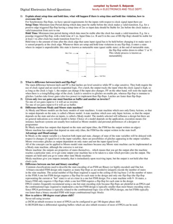
Basic ElectronicsFlip-FlopsTruth Table:𝑹𝑺𝑸𝒏𝑸𝒏 𝟏State00000101No egal)𝑹𝑺𝑸𝒏 𝟏State00𝑄𝑛No change011Set100Reset11?Forbidden(Illegal)𝑄𝑛 - Present state output𝑄𝑛 1 - Next state outputGated Flip-FlopsAn RS flip-flop (or latch) is said to be transparent, that is, any change in 𝑅 or 𝑆 isimmediately transmitted to the outputs 𝑄 and 𝑄̅ . If an enable or clock signal is connected tothe NAND gates 1 and 2, we get Gated Flip-Flops.Clocked RS Flip-FlopsIn a clocked RS flip-flop, a clock (CLK) signal is fed to the NAND gates 1 and 2 asshown in Fig. 5.Fig. 5 Clocked RS Flip-Flop (Gated RS Flip-Flop)OperationThe inputs are 𝑅 and 𝑆. The gates 3 and 4 form a NAND gate latch.When the clock is HIGH, the outputs of gates 1 and 2 are 𝑆̅ and 𝑅̅ respectively. So thelatch operates normally.When the clock is LOW, the output of the gates 1 and 2 are (1,1), which implies thatthe output does not change and the latch is said to be disabled.The operation can be analyzed for the following conditions:Shrishail Bhat, Dept. of ECE, AITM Bhatkal7
Flip-FlopsBasic Electronicsi.If 𝑪𝑳𝑲 𝟏 and 𝑹 𝑺 𝟎In this case, the outputs of gates 1 and 2 are (1,1) respectively.Let the previous state output be 𝑄 0 (𝑄̅ 1). The inputs to the gate 3 are (1,1).So its output is 𝑄 0. The inputs to the gate 4 are (0,1). So its output is 𝑄̅ 1.(The output does not change).Let the previous state output be 𝑄 1 (𝑄̅ 0). The inputs to the gate 3 are (1,0).So its output is 𝑄 1. The inputs to the gate 4 are (1,1). So its output is 𝑄̅ 0.(The output does not change).That is, if 𝐶𝐿𝐾 1 and 𝑅 𝑆 0, there is no change in the output.ii.If 𝑪𝑳𝑲 𝟏 𝐚𝐧𝐝 𝑹 𝟎, 𝑺 𝟏In this case, the outputs of gates 1 and 2 are (0,1) respectively.Let the previous state output be 𝑄 0 (𝑄̅ 1). The inputs to the gate 3 are (0,1).So its output is 𝑄 1. The inputs to the gate 4 are (1,1). So its output is 𝑄̅ 0.Let the previous state output be 𝑄 1 (𝑄̅ 0). The inputs to the gate 3 are (0,0).So its output is 𝑄 1. The inputs to the gate 4 are (1,1). So its output is 𝑄̅ 0.That is, if 𝐶𝐿𝐾 1 and 𝑅 0, 𝑆 1, the output is set (𝑄 1).iii.If 𝑪𝑳𝑲 𝟏 𝐚𝐧𝐝 𝑹 𝟏, 𝑺 𝟎In this case, the outputs of gates 1 and 2 are (1,0) respectively.Let the previous state output be 𝑄 0 (𝑄̅ 1). The inputs to the gate 3 are (1,1).So its output is 𝑄 0. The inputs to the gate 4 are (0,0). So its output is 𝑄̅ 1.Let the previous state output be 𝑄 1 (𝑄̅ 0). The inputs to the gate 4 are (1,0).So its output is 𝑄̅ 1. The inputs to the gate 3 are (1,1). So its output is 𝑄 0.That is, if 𝐶𝐿𝐾 1 and 𝑅 1, 𝑆 0, the output is reset (𝑄 0).iv.If 𝑪𝑳𝑲 𝟏 𝐚𝐧𝐝 𝑹 𝑺 𝟏In this case, the outputs of gates 1 and 2 are (0,0) respectively.Let the previous state output be 𝑄 0 (𝑄̅ 1). The inputs to the gate 3 are (0,1).So its output is 𝑄 1. The inputs to the gate 4 are (1,0). So its output is 𝑄̅ 1.Here 𝑄 1 and 𝑄̅ 1, which is not possible. So the output is not valid.Let the previous state output be 𝑄 1 (𝑄̅ 0). The inputs to the gate 3 are (0,0).So its output is 𝑄 1. The inputs to the gate 4 are (1,0). So its output is 𝑄̅ 1.Again 𝑄 1 and 𝑄̅ 1, which is not possible. So the output is not valid.That is, if 𝐶𝐿𝐾 1 and 𝑅 𝑆 1, the output is not valid. Hence this is forbidden.8Shrishail Bhat, Dept. of ECE, AITM Bhatkal
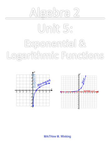
Basic Electronicsv.Flip-FlopsIf 𝑪𝑳𝑲 𝟎In this case, the output of the gates 1 and 2 are (1,1), which implies that theoutput does not change and the latch is said to be disabled.Considering all the cases, the truth table is written as below.Truth Table:𝑪𝑳𝑲𝑹𝑺𝑸𝒏𝑸𝒏 𝟏State1100000101No en(Illegal)00XXXX0101No change𝑪𝑳𝑲𝑹𝑺𝑸𝒏 𝟏State100𝑄𝑛No �𝑛No change𝑄𝑛 - Present state output𝑄𝑛 1 - Next state outputX – Don’t care(May be 0 or 1)Positive Edge-Triggered and Negative Edge-Triggered RS Flip-FlopsThe flip-flops can be positive edge triggered or negative edge triggered.i. In positive edge-triggered flip-flops, the output responds to the 𝑅 and 𝑆 inputs onlyat the positive edges of the clock pulse. At other instants of time, the output does notchange.ii. In negative edge-triggered flip-flops, the output responds to the 𝑅 and 𝑆 inputs onlyat the negative edges of the clock pulse. At other instants of time, the output does notchange.Fig. 6 shows the input and output waveforms for positive and negative edge-triggeredRS flip-flops.Fig. 6 Input and output waveforms for positive and negative edge-triggered RS flip-flopsShrishail Bhat, Dept. of ECE, AITM Bhatkal9
Flip-FlopsBasic ElectronicsIEEE Logic SymbolsAlong with traditional logic symbols, the logic gates also have IEEE functional logicsymbols.Table 2 Traditional and IEEE logic gate symbolsTable 2 shows the traditional logic symbols and their IEEE counterparts. All IEEE logicsymbols are rectangular and there is an identifying character or symbol inside.10Shrishail Bhat, Dept. of ECE, AITM Bhatkal
Basic ElectronicsFlip-FlopsQuestions1. What is a flip-flop? Distinguish between a latch and a flip-flop.(Dec ’17 – 4M, Jun ’17 – 4M, Dec ’16 – 2M, Jun ‘16, Dec ‘15, Jun ‘15 – 4M, MQP ‘14 –4M)2. What is a latch?(Dec ‘17)3. With a logic diagram and truth table, explain the operation of NAND gate latch.(Dec ’17 – 10M, Jun ’17 – 8M, Jun ‘16 – 5M)4. With a logic diagram and truth table, explain the operation of NOR gate latch.(Dec ’17, Dec ‘16 – 5M, Jun ‘16 – 8M, Dec ‘15 – 6M, MQP ‘14 – 6M)5. What is RS flip-flop? Explain its operation with circuit diagram, logic symbol andtruth table.(Dec ’17 – 6M, Jun ’17 – 8M, Jun ‘16 – 5M, Dec ‘15 – 5M, Jun ‘15 – 6M, MQP ‘15 – 6M)6. With a logic diagram and truth table, explain the operation of a clocked (or gated) RSflip-flop using NAND gates.(Dec ’17 – 8M, Jun ’17 – 8M, Dec ’16 – 8M, Jun ‘16 – 5M, Dec ‘15 – 8M, Dec ‘14 – 6M,MQP ‘15 - 4M, MQP ‘14 – 5M)7. Draw the traditional and IEEE logic symbols of AND, OR, NOT, NAND, NOR, XORand XNOR.(MQP ‘15 – 4M)References1. D.P. Kothari, I. J. Nagrath, “Basic Electronics”, McGraw Hill Education (India) PrivateLimited, 2014.2. John M. Yarbrough, “Digital Logic Applications and Design”, Thomson Learning,2001.3. Donald D. Givone, “Digital Principles and Design”, McGraw Hill, 2002.Shrishail Bhat, Dept. of ECE, AITM Bhatkal11
circuits. Combinational circuits are the circuits in which the output depends on the present inputs only. Sequential circuits are the circuits in which the output depends on the present input as well as the previous state of the system. The sequential circuits have memory. A flip-flop is the ba