Transcription
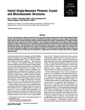
NANOLETTERSHybrid Single-Nanowire Photonic Crystaland Microresonator Structures2006Vol. 6, No. 111-15Carl J. Barrelet,† Jiming Bao,‡ Marko Lončar,‡ Hong-Gyu Park,†Federico Capasso,*,‡ and Charles M. Lieber*,†,‡Department of Chemistry and Chemical Biology and DiVision of Engineering andApplied Sciences, HarVard UniVersity, Cambridge, Massachusetts 02138Received November 21, 2005ABSTRACTWe report a hybrid approach for photonic systems that combines chemically synthesized single nanowire emitters with lithographically definedphotonic crystal and racetrack microresonator structures. Finite-difference time-domain calculations were used to design nanowire photoniccrystal structures where the photonic band gap overlaps the electronic band gap of the nanowire. Photoluminescence (PL) images of cadmiumsulfide (CdS) nanowire photonic crystal structures designed in this way demonstrate localized emission from engineered defects and lightsuppression in regions of the photonic crystal. PL spectroscopy studies of defect-free nanowire photonic crystal structures further demonstratethe photonic band gap or stop band that spans most of the CdS band edge emission spectrum. In addition, single CdS nanowire-racetrackmicroresonator structures were fabricated, and PL imaging and spectroscopy measurements show good coupling of the nanowire to themicrocavity including efficient feedback and amplified spontaneous emission. These hybrid structures exploit unique strengths of bottom-upand top-down approaches and thereby open new opportunities in nanophotonics from efficient and localized light sources to integratedoptical processing.Semiconductor nanowires1 are emerging as powerful buildingblocks for exploring a wide-range of nanophotonic devices,including light-emitting diodes,2,3 lasers,4-6 active waveguides,7and integrated electrooptic modulators.7a,8 Nanowire laser,active waveguide, and integrated electrooptic modulatorstructures exploit the optical cavity and/or waveguide properties of the semiconductor material and, thus, are distinct fromtransparent subwavelength dielectric waveguides, such asfabricated silicon on insulator structures operating at telecommunications wavelengths and silica nanowires,9 becauseabsorption and emission occur at the semiconductor nanowireband edge. Further progress with these nanowire structuresand their potential use as photonic circuit elements could belimited by poor control of the coupling of light in to and outof the nanowires. For example, CdS nanowires with diameters of 100 nm or less suffer from large losses from thenanowire cavity due to poor reflectivity of the end facets.10Hybrid structures that merge nanowire building blockswith top-down fabricated elements could offer a solution tothis fundamental issue of coupling light in to and out ofnanowires as well as enabling other opportunities. Forinstance, photonic crystals and resonant microcavities havebeen used extensively in photonics to control the couplingof light with optical cavities and to create very high quality* Corresponding authors. E-mail: capasso@deas.harvard.edu andcml@cmliris.harvard.edu† Department of Chemistry and Chemical Biology.‡ Division of Engineering and Applied Sciences.10.1021/nl0522983 CCC: 33.50Published on Web 12/23/2005 2006 American Chemical Societyfactor cavities,11 although to date there have been no reportscombining these elements with active nanowires. Herein, wereport the first studies of light-matter interaction betweensingle semiconductor nanowires and lithographically definedcavities. We demonstrate that photonic crystal structures canbe used to suppress and control spatially the emission fromspecific regions of a nanowire, and moreover, we show thatnanowires can be coupled to microresonators yieldingefficient feedback and amplified spontaneous emission.Our basic hybrid structure consists of a free-standing CdSnanowire core12 embedded in a one-dimensional (1D) photonic crystal, where the photonic crystal can be fabricatedas a uniform periodic grating or containing specificallydesigned defects as illustrated schematically in Figure 1A.To embed isolated nanowires within designed 1D photoniccrystal structures, we adopted the following approach.13 A800 nm layer of perfluorovinyl ether cyclopolymer wasdeposited on a single-crystal silicon substrate, followed bysequential deposition of a 200 nm poly(methyl methacrylate)(PMMA) layer, CdS nanowires, and a final 200 nm PMMAlayer. Electron-beam lithography was then used to define aspecific photonic crystal structure in the PMMA layers aboveand below an isolated nanowire. We note that the nanowireis supported within the photonic crystal structure withperiodic PMMA and air regions above and below the centeraxis of the nanowire. A representative scanning electronmicroscopy (SEM) image of the periodic region of a hybrid
Figure 1. Nanowire photonic crystal structure and modeling. (A)Schematic of the nanowire photonic crystal with four engineereddefects. (B) SEM image of a nanowire photonic crystal with aperiodicity, Λ ) 190 nm. Scale bar, 200 nm. (C) Dispersion diagramcalculated by FDTD simulation showing the presence of a photonicband gap. The red line is the light line in air.structure is shown in Figure 1B. This image shows that thephotonic crystal can be well-aligned relative to the individual,embedded nanowire.Finite-difference time-domain (FDTD) simulations14,15were used to determine the photonic band gap for the hybridnanowire 1D photonic crystal structures. We evaluateddifferent hybrid structures in order to achieve a good overlapof the photonic band gap with the electronic band gap ofthe CdS nanowire, 2.5 eV at 300 K.16 The calculateddispersion diagram for a 90 nm diameter CdS nanowire and190 nm period 1D photonic crystal (Figure 1C) shows thatthe photonic crystal behaves as a grating acting strongly onthe evanescent field.15 Specifically, a wide photonic bandgap exists in which light propagation along the wire issuppressed. The calculated photonic band gap, 477 λ 544 nm, spans the entire emission range of high-quality CdSnanowires, which exhibit an emission peak and full widthat half-maximum of 515 and 15 nm, respectively. Theposition and width of the photonic band gap depend on thenanowire diameter for a given periodicity17 and thus underscore the importance of the simulations in designing hybridnanowire/photonic crystal structures that are coupled.The effect of the photonic band gap on the nanowirephotonic crystal hybrid structures was first investigated byintroducing one or more PMMA defects in the periodic 1Dstructure as illustrated schematically in Figure 1A. A typicalphotoluminescence (PL) image18 recorded from a CdSnanowire photonic crystal structure with a single defectconsisting of the removal of 5 grating periods is shown inFigure 2A. This PL image, which is overlaid with a registered12Figure 2. Analysis of nanowire photonic crystal structurescontaining engineered defects. (A) PL image (false color) superimposed on the AFM image (gray scale) of a nanowire photoniccrystal with one defect. Dotted line indicates the nanowire position.Scale bar, 5 µm. (B) PL image of the same nanowire after fillingin the photonic crystal structure with PMMA. Scale bar, 5 µm. (C)PL image (false color) superimposed on the AFM image (gray scale)of a nanowire photonic crystal containing four defects, which arevisible as vertical lighter gray stripes. Scale bar, 5 µm. (D) Linescan through the PL image in (C) taken along the nanowire axis.The periodicity of the 1D grating regions in (A) and (C) was 180nm.atomic-force microscopy (AFM) image of the hybrid structure, demonstrates clearly localized radiation from theartificial defect and inhibition of emission along the nanowirephotonic crystal axis, including the nanowire ends. Controlexperiments involving the deposition of PMMA onto thephotonic crystal structures (Figure 2B), which fills in theair gaps and removes the grating, were also carried out toaddress the effects of electron beam exposure during fabrication. Notably, these PL images show that localized emissionis eliminated and conventional nanowire end emission isobserved (Figure 2B). Taken together, these data show thatthe hybrid nanowire photonic crystal structures can spatiallycontrol emission from nanowires through the introductionof defects.To further explore this concept we have fabricated andstudied the optical properties of hybrid structures withNano Lett., Vol. 6, No. 1, 2006
Figure 3. Photonic band gap in a nanowire photonic crystal PLspectrum. (A) SEM image of the hybrid structure consisting of ananowire with ribbon morphology and surrounding PMMA photonic crystal. Scale bar is 2 µm. The nanowire and orthogonalPMMA grating appear as light gray and the air gaps as thinnerdark gray stripes. (B) Normalized photoluminescence spectra withthe photonic crystal cladding (solid line) and without (dashed line).multiple defects introduced in the photonic crystal lattice.For example, a PL image of a structure with four defects isshown in Figure 2C. These data, which are registered to thecorresponding AFM image of the hybrid structure, and theline scan in Figure 2D demonstrate localized emissionspecifically from the four defect sites. In addition, PLspectroscopy studies of the localized emission did not exhibitadditional peaks in the CdS emission spectrum. These resultssuggest either that the cavity mode associated with the defecthas a low quality factor or that there is no cavity mode withinthe emission energy range. While future simulations andexperiments will be needed to address further these possibilities, we note that these studies demonstrate for the firsttime that localized emission is a robust effect in nanowirephotonic crystals with engineered defects.In addition, we have assessed the presence of the predictedphotonic band gap in the emission spectrum by fabricatingstructures to enhance out-of-plane emission from the nanowire. Specifically, a second-order grating will more efficiently scatter light out-of-plane than a first-order grating14(used above) and thereby enable better light collection bythe objective lens of the PL microscope. A SEM image ofone nanowire photonic crystal hybrid structure is shown inFigure 3A. The period of the photonic crystal, Λ ) 310 nm,was optimized using FDTD simulations for overlap of thephotonic band gap with the CdS electronic band gap for thislarger nanowire.Significantly, PL spectroscopy of this structure (Figure 3B)shows that the emission is strongly suppressed for most ofthe CdS band edge spectra, while the PL spectrum recordedNano Lett., Vol. 6, No. 1, 2006from the same nanowire without the photonic crystal showsa typical symmetric spectrum for CdS dominated by bandedge emission with peak at 514 nm. The strong contrastbetween the spectrum with and without the photonic crystalprovides direct evidence that the photonic band gap overlapswith the electronic band gap of the nanowire and that photonemission is inhibited due to the presence of the photoniccrystal. Previous measurements on CdS nanocluster syntheticopal19,20 and microsphere21 hybrids have also shown thepresence of photonic band gaps, although our resultsrepresent the first direct observation of the photonic bandgap in hybrid nanowire structures. In addition, temperaturedependent PL spectroscopy shows that the position of thephotonic band gap remains approximately fixed while thenanowire emission shifts with temperature. Together, thesestudies demonstrate that the photonic band gap in the hybridnanowire photonic crystal structures can be exploited to tunethe nanowire emission spectrum as will be required for manyphotonics applications.The generality of our approach for creating hybrid nanowire photonic systems was further explored by fabricatingnanowire racetrack microresonator structures. In contrast to1D photonic crystal cavities based on distributed feedback,nanowire microresonators trap light by total internal reflection, which provides resonant recirculation. An opticalmicrograph of a representative hybrid structure (Figure 4A)shows the racetrack microresonator defined in PMMA13 witha 2 µm track width and a 11.2 µm long, 200 nm diameterCdS nanowire embedded in one arm. The total optical lengthof the resonator, taking into account the refractive indicesof PMMA and CdS, is approximately 130 µm.22PL images recorded from the hybrid structure (Figure 4B)show strong emission at the position of the nanowire andalso exhibit emission at the edges of the opposite arm of theresonator. These results show that light emitted by thenanowire is guided by total internal reflection around theracetrack microresonator. A representative PL spectrumrecorded from the hybrid structure remote to the position ofthe embedded nanowire is shown in Figure 4C. Thisspectrum exhibits a progression of relatively sharp, periodicpeaks on top of the typical CdS emission that are suggestiveof cavity modes. The periodicity of these peaks in terms ofinverse wavelengths, 7.9 10-3 µm-1, suggests an opticallength of ca. 127 µm. An optical length of 126.7 µm wasalso obtained from the Fourier transform of the PL spectrumplotted versus reciprocal wavelength (inset, Figure 3C).Notably, the optical length determined from the spectra isin excellent agreement with the measured length of theracetrack resonator, 129 µm, and contrasts the 11.2 µm longCdS nanowire cavity length. The optical length can thus beassigned to the fundamental mode circulating around theracetrack microresonator.Last, we have further probed the nanowire racetrackmicroresonator hybrid structures by measuring the input/output power dependence at low temperatures. The PLspectrum recorded at 4 K (Figure 4D) exhibits a pronouncedpeak centered at 485 nm and several satellite peaks corresponding to cavity modes. Significantly, excitation power13
Figure 4. Nanowire racetrack microresonator. (A) White-light optical image of the nanowire/microresonator structure, where regions 1and 3 correspond to the air surrounding the PMMA racetrack, region 2. The dashed line indicates the nanowire position. Inset, 3D modelof the nanowire racetrack microresonator. (B) PL image of the nanowire microresonator. The red arrow indicates the region over whichspectra were collected and the dashed line corresponds to position of nanowire as in (A). Both scale bars, 20 µm. (C) PL spectrum recordedat room temperature at location indicated in (B). Inset, Fourier transform of the PL spectrum. (D) PL spectrum at ca. 4 K. Inset, peak outputpower versus incident pump power.dependent measurements (inset, Figure 4D) show a superlinear increase in the output emission intensity as a functionof incident laser power with an exponent of 2.9. Thesuperlinear increase in the emission output power and theemergence of a dominant mode from the relatively broadspectrum are consistent with amplified stimulated emissionfrom the hybrid structure. We believe that further refinementof the nanowire/microresonator hybrid structures (e.g., reducing the optical losses of the racetrack resonator) has thepotential to generate low-threshold external cavity nanowirelasers with the fabricated racetrack enabling a number optionsbeyond that possible with the nanowire alone.In summary, we have described a hybrid approach forphotonic systems that combines bottom-up synthesis of singlenanowire emitters with lithographically defined photonicstructures. We used this approach to study light-matterinteractions at the single nanowire level in two systems, thenanowire 1D photonic crystal and the nanowire racetrackresonator. FDTD calculations were used to design nanowirephotonic crystal structures where the photonic band gapoverlaps the electronic band gap of the nanowire. PL imagesof CdS nanowire photonic crystal structures designed in thisway demonstrated localized emission from engineereddefects and light suppression in regions of the photonic14crystal. PL spectroscopy studies of defect-free nanowirephotonic crystal structures further showed that the photonicband gap can span most of the CdS band edge emissionspectrum and thereby control the nanowire emission spectrumas will be required for many photonics applications. Inaddition, single CdS nanowire racetrack microresonatorstructures were fabricated, and PL imaging and spectroscopymeasurements showed good coupling of the nanowire to themicrocavity including efficient feedback and amplifiedspontaneous emission. While these studies, which exploitunique strengths of bottom-up and top-down approaches,have focused on single nanowire devices, emerging methodsfor hierarchical assembly using holographic optical tweezers23and other techniques2a,24 could enable parallel and scalableorganization of compact photonic integrated circuits.Acknowledgment. We thank Chen Yang and Hao Yanfor the AFM measurements. H.G.P. acknowledges supportfrom the Korea Research Foundation Grant (KRF-2005-214C00054). C.M.L. acknowledges support of this work by theAir Force Office of Scientific Research. F.C. acknowledgespartial support by the National Science Foundation NanoscaleScience and Engineering Center and by the Center forNanoscale Science at Harvard University.Nano Lett., Vol. 6, No. 1, 2006
References(1) (a) Hu, J.; Odom, T.; Lieber, C. M. Acc. Chem. Res. 1999, 32, 435.(b) Lieber, C. M. MRS Bull. 2003, 28, 486. (c) Yang, P. MRS Bull.2005, 30, 85.(2) (a) Duan, X.; Huang, Y.; Cui, Y.; Wang, J.; Lieber, C. M. Nature2001, 409, 66. (b) Zhong, Z.; Qian, F.; Wang, D.; Lieber, C. M.Nano Lett. 2003, 3, 343. (c) Huang, Y.; Duan, X.; Lieber, C. M.Small 2005, 1, 142.(3) (a) Qian, F.; Li, Y.; Gradeèak, S.; Barrelet, C. J.; Wang, D.; Lieber,C. M. Nano Lett. 2004, 4, 1975. (b) Kim, H.; Cho, Y.; Lee, H.; Kim,S.; Ryu, S. R.; Kim, D. Y.; Kang, T. W.; Chung, K. S. Nano Lett.2004, 4, 1059. (c) Qian, F.; Gradecak, S.; Li, Y.; Wen, C.-Y.; Lieber,C. M. Nano Lett. 2005, 5, 2287.(4) (a) Huang, M. H.; Mao, S.; Feick, H.; Yan, H.; Wu, Y.; Kind, H.;Weber, E.; Russo, R.; Yang, P. Science 2001, 292, 1897. (b) Johnson,J. C.; Choi, H. J.; Knutsen, K. P.; Schaller, R. D.; Yang, P.; Saykally,R. J. Nat. Mater. 2002, 1, 106.(5) Duan, X.; Huang, Y.; Agarwal, R.; Lieber, C. M. Nature 2003, 421,241.(6) (a) Agarwal, R.; Barrelet, C. J.; Lieber, C. M. Nano Lett. 2005, 5,917. (b) Gradecak, S.; Qian, F.; Li, Y.; Park, H.-G.; Lieber, C. M.Appl. Phys. Lett. 2005, 87, 173111.(7) (a) Barrelet, C. J.; Greytak, A. B.; Lieber, C. M. Nano Lett. 2004, 4,1981. (b) Law, M.; Sirbuly, D. J.; Johnson, J. C.; Goldberger, J.;Saykally, R. J.; Yang, P. Science 2004, 305, 1269.(8) Greytak, A. B.; Barrelet, C. J.; Li, Y.; Lieber, C. M. Appl. Phys.Lett. 2005, 87, 151103.(9) (a) Vlasov, Y. A.; McNab S. J. Opt. Express 2004, 12, 1622. (b)Tong, L.; Gattass, R.; Ashcom, J.; He, S.; Lou, J.; Shen, M.; Maxwell,I.; Mazur, E. Nature 2003, 426, 816.(10) Maslov, A. V.; Ning, C. Z. Appl. Phys. Lett. 2003, 83, 1237.(11) (a) Vahala, K. J. Nature 2003, 424, 839. (b) Joannopolulos, J. D.;Meade, R. D.; Winn, J. N. Photonic Crystals; Princeton UniversityPress: Princeton, NJ, 1995.(12) Barrelet, C. J.; Wu, Y.; Bell, D. C.; Lieber, C. M. J. Am. Chem. Soc.2003, 125, 11498.(13) A 800 nm layer of perfluorovinyl ether cyclopolymer CYTOP/CTL809M (Asahi Glass, Tokyo Japan) with a refractive index of 1.3 wasdeposited on a single-crystal silicon substrate, followed by sequentialdeposition of a 200 nm poly(methyl methacrylate) (PMMA) layer,CdS nanowires, and a final 200 nm PMMA layer. Electron-beamlithography (electron energy ) 30 keV) followed by developmentfor 90 s in a solution of methyl isobutyl ketone/isopropyl alcohol,3:1, was then used to define a specific photonic crystal structure inthe PMMA layers above and below an isolated nanowire. A similarprocedure was used to define nanowire racetrack microresonantorhybrid structures.(14) Taflove, A.; Hagness, S. C. Computational Electrodynamics; ArtechHouse: Boston, 2000.(15) The time-dependent Maxwell’s equations were solved using theFDTD method on a computational grid with Bloch boundaryconditions.14 This time-domain method is used extensively in thephotonic crystal literature to model subwavelength waveguides.11bThe three inputs in the simulation are (i) a computational unit cell,Nano Lett., Vol. 6, No. 1, 2006(16)(17)(18)(19)(20)(21)(22)(23)(24)(ii) an initial field defined as a Dirac pulse in time, with Gausianprofile in space, and (iii) a k value. The 3D unit cell consists of oneperiodicity of the nanowire photonic crystal and is divided into agrid where each point is given a refractive index to best map thehybrid structure; indices of 1, 1.5, and 2.8 were used for air, PMMA,and CdS, respectively. In our simulations, the initial field is locatedin the nanowire. The FDTD simulation then stores the time evolutionof the field. The simulation results were Fourier transformed toconvert the field components to the frequency domain, and the fieldamplitude versus frequency were plotted to determine resonancemodes and their corresponding energies. The procedure was repeatedfor different k values until the dispersion diagram is obtained overthe region of interest. The resonance modes depend on both nanowirediameter and photonic crystal periodicity. For small nanowirediameter, the evanescent field is large and consequently the overlapbetween the field and the photonic crystal is large. For large nanowirediameter, the evanescent field is smaller and correspondingly theoverlap between the field and the photonic crystal is small. FDTDcalculations provide key guidelines for the design of hybrid structuresand interpretation of experiments but could be improved in the futureby taking into account absorption and emission processes in thenanowire.Cardona, M.; Yu, P. Y. Fundamentals of Semiconductors; Springer:New York, 2001.For example, FDTD calculations made on structures with 70 and126 nm diameter nanowires, which are smaller and larger than actualnanowire, yield calculated photonic band gaps of 430 λ 510nm and 570 λ 590 nm, respectively, for a grating periodicity ofΛ ) 180 nm.All nanowire structures studied were optically pumped by a doubledTi/sapphire laser with a wavelength of 400 nm. The Gaussian laserspot was centered on the nanowire structure, and the spot size wasintentionally made large enough to illuminate the entire length ofthe nanowire. The light emitted from the structure is collected byeither a 40 or a 100 objective focused onto the entrance of a 300mm spectrometer and either imaged or dispersed onto a cooled CCD.Romanov, S. G.; Fokin, A. V.; Alperovich, V. I,; Johnson, N. P.; DeLa Rue, R. M. Phys. Status Solidi A 1997, 164, 169.Blanco, A.; Lopez C.; Mayoral, R.; Miguez, H.; Meseguer F.; MifsudA.; Herrero, J. Appl. Phys. Lett. 1998, 73, 1781.Lin, Y.; Zhang, J.; Sargent, E. H.; Kumacheva, E. Appl. Phys. Lett.2002, 81, 3134.The path length, L, and the refractive indices, n, are used to estimatethe optical length of the racetrack resonator. The length of the PMMAin the racetrack is 64.8 µm and the length of the CdS nanowire is11.2 µm. The index of PMMA and CdS are 1.5 and 2.8, respectively.L(PMMA) n(PMMA) L(CdS) n(CdS) gives a total path lengthof 129 µm.Agarwal, R.; Ladavac, K.; Roichman, Y.; Yu, G.; Lieber, C. M.;Grier, D. G. Opt. Express 2005, 13, 8906.(a) Huang, Y.; Duan, X.; Wei, Q.; Lieber, C. M. Science 2001, 291,630. (b) Whang, D.; Jin, S.; Wu, Y.; Lieber, C. M. Nano Lett. 2003,3, 1255.NL052298315
190 nm period 1D photonic crystal (Figure 1C) shows that the photonic crystal behaves as a grating acting strongly on the evanescent field. 15 Specifically, a wide photonic band gap exists in which light propagation along the wire is suppressed. The calculated photonic band gap, 477 ! 544