Transcription
AEM Performance Electronics2205 W 126th Street, Unit AHawthorne, CA 90250Phone (8am-5pm M-F PST): 310-484-2322Fax: 310-484-0152sales@aemev.comtech@aemev.comAEM EVVCU300 User GuideRevision A
AEM Performance Electronics2205 W 126th Street, Unit AHawthorne, CA 90250Phone (8am-5pm M-F PST): 310-484-2322Fax: 310-484-0152sales@aemev.comtech@aemev.comRevision HistoryRevisionADate7/6/2020Change DescriptionInitial ReleaseCautions and WarningsWorking on tractive systems (which includes but is not limited to motor(s), inverter(s), high voltage battery packs andhigh voltage cables) requires special experience and training. AEM EV has implemented fault detection and failsafe logicinto its vehicle control units (“VCU”), however this does not mean that your VCU installation will be safe or effective, orthat your VCU installation will not interfere with other systems on your vehicle and create a hazardous situation. It is theresponsibility of the installer to understand the implications of each stage of tractive system installation and testing andto recognize what might be unique about your application that presents potential hazards or safety issues – and it is theresponsibility of the installer to solve or address any such hazards or issues.The following list includes basic recommended practices. This is not a comprehensive list; as noted below, if you are notwell-versed in the appropriate installation and testing procedures, you should refer the installation and calibration to areputable installation facility or contact AEM EV for a referral in your area. When access is required near the battery pack, the cell segments must be separated by using an appropriatemaintenance disconnect plug. When working on the battery pack or tractive system, safety gloves with side shields and appropriate insulatedtools must be used. Always wear Class 0 gloves rated at 1000V with leather protectors. Only use CAT III rated digital multimeters (DMM) and test leads. When working on the battery pack or tractive system, work with one hand while keeping the other behind yourback. During initial system power up and testing, the vehicle must be raised off the ground and supportedappropriately. Wheels and tires should be removed. During the VCU firmware upgrade process, battery cell segments must be separated using an appropriatemaintenance disconnect plug. Do not make calibration changes when the inverter pulse width modulation (PWM) is enabled.USE THIS VCU WITH EXTREME CAUTION. MISUSE AND/OR IMPROPER INSTALLATION CAN CAUSE SIGNIFICANT DAMAGETO YOUR VEHICLE AND PROPERTY BELONGING TO YOU OR OTHERS, AS WELL AS PERSONAL INJURY OR DEATH. IF YOUARE NOT WELL VERSED IN THE INSTALLATION OF TRACTIVE SYSTEMS OR CONFIGURING THE CALIBRATIONS IN THE AEMEV VCU THAT ARE NECESSARY TO CONTROL THE VEHICLE, YOU SHOULD REFER THE INSTALLATION AND VCUCALIBRATION TO A REPUTABLE INSTALLATION FACILITY, OR CONTACT AEM EV FOR A REFERRAL IN YOUR AREA. IT IS THERESPONSIBILITY OF THE INSTALLER TO ULTIMATELY CONFIRM THAT THE INSTALLATION AND CALIBRATIONS ARE SAFEFOR ITS INTENDED USE.7/6/2020, Revision AAEM EV VCU300 User GuidePage 2 of 18
AEM Performance Electronics2205 W 126th Street, Unit AHawthorne, CA 90250Phone (8am-5pm M-F PST): 310-484-2322Fax: 310-484-0152sales@aemev.comtech@aemev.comADVANCED ENGINE MANAGEMENT CO., INC. (“AEM”) AND ITS AFFILIATES, SHAREHOLDERS, DIRECTORS, OFFICERS,AGENTS, REPRESENTATIVES, SUCCESSORS AND ASSIGNS (COLLECTIVELY, THE “AEM PARTIES”) HOLD NO RESPONSIBILITYFOR ANY DAMAGE OR INJURY THAT RESULTS FROM INSTALLATION OR MISUSE OF ANY AEM PRODUCTS. EXCEPT FOR, TOTHE EXTENT APPLICABLE TO THE PRODUCTS YOU HAVE PURCHASED, AEM’S 12 MONTH LIMITED WARRANTY (WHICHCAN BE FOUND AT eturns ), ALL AEM PRODUCTS ARE PROVIDED“AS IS” AND THE AEM PARTIES EXPRESSLY DISCLAIM ALL WARRANTIES, WHETHER EXPRESS, IMPLIED, STATUTORY OROTHERWISE. THE AEM PARTIES SPECIFICALLY DISCLAIM ALL IMPLIED WARRANTIES OF MERCHANTABILITY AND FITNESSFOR A PARTICULAR PURPOSE, AND ALL WARRANTIES ARISING FROM COURSE OF DEALING, COURSE OF PERFORMANCE,USAGE OR TRADE PRACTICE.UNDER NO CIRCUMSTANCES SHALL ANY AEM PARTY BE LIABLE TO YOU OR ANY OTHER PERSON OR ENTITY FOR ANYDAMAGES OF ANY AMOUNT OR CHARACTER (INCLUDING, WITHOUT LIMITATION, ANY GENERAL, INDIRECT, SPECIAL,INCIDENTAL, EXEMPLARY, CONSEQUENTIAL OR PUNITIVE DAMAGES) ARISING OUT OF, RELATED TO, OR IN CONNECTIONWITH (1) YOUR INSTALLATION OF ANY AEM PRODUCTS OR (2) YOUR MISUSE OF ANY AEM PRODUCTS. IN NO EVENTSHALL ANY AEM PARTY BE LIABLE TO YOU OR ANY OTHER PERSON OR ENTITY FOR ANY LOST OR CORRUPTED DATA,LOST PROFITS, LOST REVENUES, LOSS OF USE, DIMINUTION IN VALUE, LOSS OF OTHER INTANGIBLES OR ANY SPECIAL,INCIDENTAL, INDIRECT, EXEMPLARY, PUNITIVE OR CONSEQUENTIAL DAMAGES, WHETHER ARISING OUT OF BREACH OFCONTRACT, TORT (INCLUDING NEGLIGENCE) OR OTHERWISE, REGARDLESS OF WHETHER SUCH DAMAGES WEREFORESEEABLE AND WHETHER OR NOT THE AEM PARTIES WERE ADVISED OF THE POSSIBILITY OF SUCH DAMAGES.SOME JURISDICTIONS MAY NOT ALLOW THE EXCLUSION OR LIMITATION OF INCIDENTAL OR CONSEQUENTIALDAMAGES, SO THE ABOVE EXCLUSIONS SHALL ONLY APPLY TO THE EXTENT PERMISSIBLE UNDER APPLICABLE LAW.Electrical Safety Insulation MonitoringThe high voltage system in an electric vehicle is designed to be ungrounded (floating) with respect to the vehicle chassis(frame). Insulation faults can cause electric shock, personal injury and even death. An insulation monitoring device(IMD) must be used to protect against these faults. See Bender https://www.benderinc.com/ for more information.7/6/2020, Revision AAEM EV VCU300 User GuidePage 3 of 18
AEM Performance Electronics2205 W 126th Street, Unit AHawthorne, CA 90250Phone (8am-5pm M-F PST): 310-484-2322Fax: 310-484-0152sales@aemev.comtech@aemev.comHardware OverviewAEM Part NumberMicroprocessorClock SpeedEnvironmentalOperating TemperatureOperating VoltageOvervoltage ProtectionCurrent Draw: Off-State CurrentReverse Polarity Supply VoltageWake Switch Power-on thresholdWake Switch Power-off thresholdLoad dump protectionMain RelayCommunication ChannelsInternal Logging Memory30-8100Infineon Tricore TC1793200/260 MHzIP6k9k Compliant-40 C to 105 C9 – 16V16V is the absolute maximum rating. The module is not designed for usewith 16V battery systems as they typically require 18V to charge.38.5V8.4 mA13.5V for 5 min4.13V minimum3.61V maximumLoad dump on the 12V supply lines must be less than 36VA VCU controlled main relay is required. Main relay must be source forloads driven by lowside drivers.CAN1, 500k, NOT internally terminated, PC CommsCAN2, 500k, Internally Terminated, Peripheral Device CommsCAN3, 500k, NOT internally terminated, Peripheral Device Comms andData TransmitNone - External logging possible with AEM Dash units with loggingcapability and other compatible 3rd party displays and data loggers.About this documentThis document is not a comprehensive step by step guide to every feature available. It is intended to get the VCUpowered up properly and running quickly in a bench top environment. Along the way you will become familiar withcertain core features. Your primary source for detailed information about VCU functionality is AEMCal. Nearly allfeatures are described using tool tips, compiled help or description pane help. The AEMCal screen capture images in thisdocument are accurate at the time of publication. However, AEMCal and the AEMCal layout files provided by AEM willbe updated over time. In the event of a discrepancy, always follow the instructions contained within the layout file.Software Tools InstallationGo to https://www.aemev.com/documentation/download to download the installers for AEMCal and AEMData. Runboth installers to install both tools. During the installation, choose to install the desktop icon. After the installation,restart your PC.Launch AEMCal from the desktop icon.7/6/2020, Revision AAEM EV VCU300 User GuidePage 4 of 18
AEM Performance Electronics2205 W 126th Street, Unit AHawthorne, CA 90250Phone (8am-5pm M-F PST): 310-484-2322Fax: 310-484-0152sales@aemev.comtech@aemev.comA Quick Start pane will provide options. Click Show Helpto launch the online help for AEMCal. Read andunderstand all sections before continuing. Theinstructions that follow assume you have read theAEMCal online help content.PC Communications with AEMCalThe VCU300 communicates with the PC over the CAN1 network. A CAN to USB converter device is required. For bestperformance, AEM recommends the Kvaser Leaf Light HS v2 s-v2/Once you have the adapter, navigate to the Kvaser DOWNLOADS tab and click the Download button for the KvaserDrivers for Windows. Note that the Version may not necessarily match the Version in the example image below. Runthe executable to install the hardware drivers. It is always a good idea to restart your PC after installing new hardwaredrivers. Please do so.Harness ConnectorsA mating Plug & Pin Kit is available from AEM under PN 30-3710. Following is a list of Bosch recommended tools forworking with these connector assemblies. There may be similar and/or compatible tools available in the market.However, AEM will not be responsible for connector housing damage caused by misuse or use of improper tools. If youare not comfortable working with high density connector housings, please seek help from an experienced automotiveharness builder. A properly planned and assembled harness is critical for performance and safety.ToolLarge Terminal CrimpSmall Terminal CrimpTerminal Depinning7/6/2020, Revision ABosch Part Number1 928 498 2131 928 498 2121 928 498 997AEM EV VCU300 User GuidePage 5 of 18
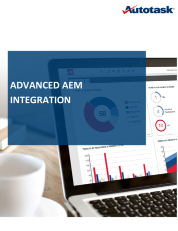
AEM Performance Electronics2205 W 126th Street, Unit AHawthorne, CA 90250Phone (8am-5pm M-F PST): 310-484-2322Fax: 310-484-0152sales@aemev.comtech@aemev.comMinimum Power and Programming RequirementsAEM recommends that you familiarize yourself with the VCU200 basic functionality within a bench top environmentAND NOT ON A VEHICLE during the first power up and test.1. Launch AEMCal. A USB connection to the VCUhardware is not required yet.2. Open the FactoryBase calibration which shouldbe in r.3. Load the Default300 layout file which should bein the \Documents\AEM\AEMcal\Layouts\Factoryfolder.4. Select the Setup-Hardware groupFamiliarize yourself with the Hardware Pinout. There aremultiple tabs in this pane (Pinout1-10).7/6/2020, Revision AAEM EV VCU300 User GuidePage 6 of 18
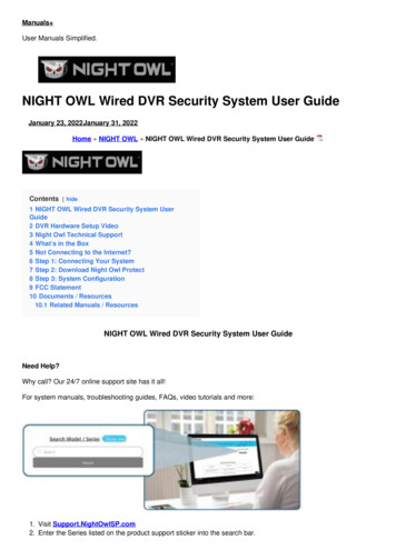
AEM Performance Electronics2205 W 126th Street, Unit AHawthorne, CA 90250Phone (8am-5pm M-F PST): 310-484-2322Fax: 310-484-0152sales@aemev.comtech@aemev.comSelect the MinimumPowerReq tab which includes anexample wiring schematic and general information aboutpower distribution. Use the Hardware Pinout and theMinimum Power schematic shown to build a test benchharness that can be powered from a 12V bench toppower supply.Select the PC Connection tab. Assemble and add a PCcommunications stub to your harness. Use the exampleschematic for reference. The VCU300 communicateswith your PC via a CAN to USB adapter. If you do nothave experience assembling harnesses for use in vehiclenetworks, please seek help from an experiencedautomotive harness builder. The VCU300 functions as aCAN network data hub. Proper network wiring is criticalfor performance and safety.7/6/2020, Revision AAEM EV VCU300 User GuidePage 7 of 18
AEM Performance Electronics2205 W 126th Street, Unit AHawthorne, CA 90250Phone (8am-5pm M-F PST): 310-484-2322Fax: 310-484-0152sales@aemev.comtech@aemev.com1. Connect your CAN to USB adapter to an availableUSB port on your PC.2. Within AEMCal, go to ECU Connection Setup 3. In the Port pane, ensure your settings match theexample at left.4. Select your CAN to USB adapter from the CANPort dropdown selection list. If your devicedrivers were installed correctly, your adaptershould appear in this list. The example shows theKvaser Leaf Light v2. If it does not appear, tryrestarting AEMCal. If you still have problems,there may be an issue with your adapter devicedriver installation. Stop and contact the adaptermanufacturer for troubleshooting support.1. Connect the power leads of your test harness toyour 12V bench top power supply.2. Set the power supply current limit toapproximately 1.0 amp.3. Turn the power supply switch on.4. Using your harness, turn the VCU ‘Key Switch’ on.5. At power up, the VCU should draw between 100and 500 mA depending on other loads present inthe harness. A lighted switch may create morecurrent draw. If the current is not within thisrange, double check your power distributionwiring.6. Connect the CAN to USB adapter to your harnessDB9 communications interface.7. Go to ECU Connect or the Shift F7 hotkeycombo. AEMCal will attempt to connect to yourVCU.AEMCal will present a similar window to the one shownat left. A scroll bar will indicate connection progress asAEMCal retrieves calibration data from your VCU. If youdo not see this progress bar at first, click Abort and:1. Make sure there are no other devices connectedor applications running that may be using your PCUSB ports.2. Double check the pinout of the harness DB9interface connector.3. Disconnect the CAN to USB adapter from your PCthen plug it back in.4. Try restarting AEMCal and repeating the process.If you got this far, congratulations! Your VCU is poweredup and communicating with AEMCal.7/6/2020, Revision AAEM EV VCU300 User GuidePage 8 of 18
AEM Performance Electronics2205 W 126th Street, Unit AHawthorne, CA 90250Phone (8am-5pm M-F PST): 310-484-2322Fax: 310-484-0152sales@aemev.comtech@aemev.comBasic VCU Function Check & AEMCal Work Space Tour1. Within AEMCal, navigate to the Setup-Hardware group and select the MinimumPowerReq tab.2. Live data from the VCU will be presented in the Channels list. Note the green Online indication in the lowerright. Note the Description Pane. If you do not see the Description Pane, go to View Descriptions or hitCntrl D.3. Ensure that:a. The VCU 12V Input internal measurement matches (approximately) the output from your powersupply.b. The VCU 5V Output internal measurement is close to 5 volts.c. The Run Time Counter is incrementing.d. The EEPROM State indicates Loaded Saved Values – Normal Startup.Congratulations! Another milestone passed.7/6/2020, Revision AAEM EV VCU300 User GuidePage 9 of 18
AEM Performance Electronics2205 W 126th Street, Unit AHawthorne, CA 90250Phone (8am-5pm M-F PST): 310-484-2322Fax: 310-484-0152sales@aemev.comtech@aemev.comSafety Warning Acknowledgement1. Within the Warnings group, view theWarningStatement tab.2. Read the warning statement.3. After reading and acknowledging thestatement, Select Yes for theSafetyWarningAknowledgmentsetting.The VCU must be powered up and connectedto AEMCal before making this change. If youdo not acknowledge this statement, the VCUwill only allow a 0.0 N.m torque commandregardless of any other calibration settings.7/6/2020, Revision AAEM EV VCU300 User GuidePage 10 of 18
AEM Performance Electronics2205 W 126th Street, Unit AHawthorne, CA 90250Phone (8am-5pm M-F PST): 310-484-2322Fax: al Configuration OptionsThere are several fundamental configuration settingsrequired.1. Go to the Setup-ConfigOptions group and selectthe Configuration tab.2. Select each setting and read the Description fieldfor definitions and instructions.3. Make your selections to configure the VCU foryour application.Minimum Required Inputs SetupThe following sections describe setup of the minimum required inputs. These steps assume the inputs are connected tothe VCU and the VCU is powered up and running. Before proceeding, use the VCU pinout table in the Setup-Hardwaregroup, HardwarePinout tab as a reference for adding the inputs to your harness. These include:1.2.3.4.5.6.Ignition SwitchAccelerator PedalBrake SwitchDrive Mode PRND inputsMain HVIL LoopIMDAEM recommends adding these inputs to your bench test harness. It is much easier to debug harness assemblyproblems within a bench test environment.7/6/2020, Revision AAEM EV VCU300 User GuidePage 11 of 18
AEM Performance Electronics2205 W 126th Street, Unit AHawthorne, CA 90250Phone (8am-5pm M-F PST): 310-484-2322Fax: 310-484-0152sales@aemev.comtech@aemev.comIgnition Switch1. Go to the Setup-Inputs group and select theIgnitionSwitch tab.2. Read the notes, Descriptions and wiring diagram.3. Configure the settings for your application.7/6/2020, Revision AAEM EV VCU300 User GuidePage 12 of 18
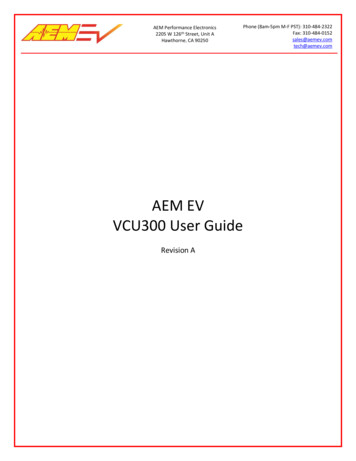
AEM Performance Electronics2205 W 126th Street, Unit AHawthorne, CA 90250Phone (8am-5pm M-F PST): 310-484-2322Fax: or PedalSelect the AccelPedal tab. This tab islarge but for most applications, thereare only a handful of settings changesrequired. The basic pedal calibrationprocess is as follows. See notes andDescriptions in the tab for moredetails.1. With the pedal closed,monitor the channelAPPX Volts vs the optionAPPX Min. Set APPX Min APPX Volts.2. With the pedal fully open,monitor the channelAPPX Volts vs the optionAPPX Max. Set APPX Max APPX Volts.3. Set the APPX Hi Thresh andAPPX Lo Thresh slightlyoutside these calibrationlimits. These will be your faultdetection thresholds.7/6/2020, Revision AAEM EV VCU300 User GuidePage 13 of 18
AEM Performance Electronics2205 W 126th Street, Unit AHawthorne, CA 90250Phone (8am-5pm M-F PST): 310-484-2322Fax: 310-484-0152sales@aemev.comtech@aemev.comBrake SwitchA properly setup and configured Brake Switch input iscritical for safety and functionality.1. Go to the Setup-Inputs group and select theBrakeSwitch tab.2. Use the example wiring diagram to add the BrakeSwitch input to your VCU.3. Read the notes and Descriptions and configurefor your application.Drive Mode PRND InputsDiscrete PRND switch inputs are required for indirectdrive applications. There is a choice between discreteswitch inputs or the AEM 8-Button CAN Keypad for directdrive applications.1. Go to the Setup-Inputs group and select thePRND tab.2. Use the example wiring diagram to add theswitch inputs to your VCU.3. Read the notes and Descriptions and configurefor your application.7/6/2020, Revision AAEM EV VCU300 User GuidePage 14 of 18
AEM Performance Electronics2205 W 126th Street, Unit AHawthorne, CA 90250Phone (8am-5pm M-F PST): 310-484-2322Fax: 310-484-0152sales@aemev.comtech@aemev.comMain HVIL LoopA completed Main HVIL loop is required for high voltagecontactor function.1. Go to the Setup-Inputs group and select theHVILMain tab.2. Use the example wiring diagram to add the loopto your VCU.IMD SetupThe high voltage system in an electric vehicle is designedto be ungrounded (floating) with respect to the vehiclechassis (frame). Insulation faults can cause electric shock,personal injury and even death. An insulation monitoringdevice (IMD) must be used to protect against these faults.See Bender https://www.benderinc.com/ for moreinformation.1. Go to the Setup-Inputs group and select the IMDtab.2. Read all notes and Description text and configurefor your application.VCU Outputs SetupIn most cases, there are options for output control. In cases where an AEM PDU-8 control output is available, werecommend using the PDU-8 over other methods. The current limiting and fault detection features increase safety andreliability. This is especially important for high voltage contactor control.7/6/2020, Revision AAEM EV VCU300 User GuidePage 15 of 18
AEM Performance Electronics2205 W 126th Street, Unit AHawthorne, CA 90250Phone (8am-5pm M-F PST): 310-484-2322Fax: 310-484-0152sales@aemev.comtech@aemev.com1. Go to the Setup-Outputs group and select the PDU8-1 through PDU8-4 tabs.2. Review the pinout table for VCU functions for each output channels. These output functionsare not re-assignable.3. Manual override settings are available for testing each output. Set the OvrVal to 1 then setthe OvrSts to override to override the the output logic.4. Refer to the user instructions provided with the AEM PDU8 for more information on hardwarecapabilities and wiring.CAUTION!Do not manually override high voltage contactor drivers when they are connected to the batterypack.7/6/2020, Revision AAEM EV VCU300 User GuidePage 16 of 18
AEM Performance Electronics2205 W 126th Street, Unit AHawthorne, CA 90250Phone (8am-5pm M-F PST): 310-484-2322Fax: 310-484-0152sales@aemev.comtech@aemev.comInverter PreCharge Setup1. Go to the Setup-Outputs group and select theHighVoltageContactors tab.2. These settings must be configured properlyfor your high voltage battery pack range.Familiarize yourself with the Description foreach option and channel.3. Configure the settings for your application.The ContactorPreConditions channel list is helpfulinformation for first time setups. Read theDescription for each channel and monitor duringInverter PreCharge.CAUTION!Do not manually override high voltage contactor drivers when they are connected to the battery pack.Additional Features and FunctionsThis document is just an introduction to the many features and functions of the VCU300. See the AEM factory layoutalong with the help content within AEMCal for more detailed information.7/6/2020, Revision AAEM EV VCU300 User GuidePage 17 of 18
AEM Performance Electronics2205 W 126th Street, Unit AHawthorne, CA 90250Phone (8am-5pm M-F PST): 310-484-2322Fax: 310-484-0152sales@aemev.comtech@aemev.com12 Month Limited WarrantyAEM Performance Electronics warrants to the consumer that all AEM Electronics products will be free from defects inmaterial and workmanship for a period of twelve months from the date of the original purchase. Products that failwithin this 12-month warranty period will be repaired or replaced when determined by us that the product failed due todefects in material or workmanship. This warranty is limited to the repair or replacement of the AEM Electronics part.This warranty applies only to the original purchaser of the product and is non-transferable. All implied warranties shallbe limited in duration to the said 12-month warranty period. Improper use or installation, accident, abuse, unauthorizedrepairs or alterations performed by the user on any AEM Electronics products voids this warranty.In no event shall this warranty exceed the original purchase price of the AEM Electronics part nor shall AEM Electronicsbe responsible for special, incidental or consequential damages or cost incurred due to the failure of this product.AEM Electronics disclaims any liability for consequential damages due to breach of any written or implied warranty onall of its products.Warranty returns will only be accepted by AEM Electronics when accompanied by a valid Return MerchandiseAuthorization (RMA) number and a dated proof of purchase. The product must be received by AEM Electronics within 30days of the date the RMA is issued. Warranty claims to AEM Electronics must be shipped to us prepaid (we recommenda shipping service with package tracking capability). Once your package is received by our warranty and repairsdepartment you will be notified and provided with updates.PROCEDURES FOR ISSUANCE OF A RETURN MERCHANDISE AUTHORIZATION (RMA) NUMBER–Please note that before AEM Electronics can issue an RMA for any product, it is first necessary for the installer or enduser to contact our technical support team to discuss the problem. Most issues can be resolved over the phone. Underno circumstances should a system be returned, or an RMA requested before our support team is contacted. This willensure that if an RMA is needed that our team is able to track your product through the warranty process.You can reach our Tech Support Team for support on all AEM Electronics performance products by phone at 1-800-4230046. To contact us by email for engine management systems, email us at emstech@aemelectronics.com. For all otherproducts, email us at gen.tech@aemelectronics.com.AEM Electronics will not be responsible for products that are installed incorrectly, installed in a non-approvedapplication, misused, or tampered with. In the case of AEM Electronics Fuel Pumps, incorrect polarity ( &- wirescrossed) will not be warranted. Proper fuel filtration before and after the fuel pump is essential to fuel pump life. Anypump returned with contamination will not be warranted.PRODUCTS OUTSIDE OF WARRANTY PERIODAny AEM Electronics product, excluding discontinued products, can be returned for repair if it is out of the warrantyperiod. There is a minimum charge of 50.00 for inspection and diagnosis of AEM Electronics parts. Parts used in therepair of AEM Electronics components will be extra. AEM Electronics will provide an estimate of repairs and mustreceive written or electronic authorization from you before repairs are made to a product.7/6/2020, Revision AAEM EV VCU300 User GuidePage 18 of 18
AEM Performance Electronics 2205 W 126th Street, Unit A Hawthorne, CA 90250 Phone (8am-5pm M-F PST): 310-484-2322 Fax: 310-484-0152 sales@aemev.com tech@aemev.com