Transcription
User ManualThermo ScientificOrion 2111LLLow Level Sodium AnalyzerUM-263639-004 Revision C October 2013
ContentsSection 1General Information. 6Section 2Analyzer Preparation . 16Section 3Analyzer Operation . 29Introduction . 6Markets . 6Applications . 7Features and Benefits. 7Principles of Operation . 8Principles of Calibration . 9Double Known Addition (DKA) . 10Offline Calibration. 11Blank Correction. 11Glossary. 13Two Channel Analyzer Configurations. 15Unpacking the Analyzer . 16Mounting and Plumbing Instructions . 17Recommendations . 17Instructions . 17Sample Requirements . 17Electrical Wiring . 18Safety Requirements . 18Warning Labels and Locations . 19Wiring the Analyzer. 19Required Tools . 19Meter Inputs . 20Terminal Assignments . 21Electrode Wiring Assignments . 21Installation of DIPA Reagent and Diffusion Tubing . 23Recommendations . 23DIPA Diffusion Tubing Assembly . 23Diffusion Tubing Installation . 24DIPA Reagent Bottle Installation . 25Installation of New Electrode Cables . 26Ferrite Installation. 26Conditioning and Installation of a New Sodium Electrode . 26Installation of the ATC Probe . 27Installation of a New Reference Electrode . 27Description of Basic Controls . 29Description of Keypad Icons . 31Use of the Setup Mode . 32Navigating Tips for the Setup Mode . 32Channel Specific Menu Options in the Setup Mode . 33Using Password Protection . 33Setup Mode Overview . 34General Setup Mode Menu Options . 34Channel Specific Setup Mode Menu Options . 35Shutdown and Start-Up Procedure . 62
Section 1 General InformationShutdown . 62Start-Up . 63Section 4Calibration . 64Section 5Analyzer Maintenance . 82Section 6Troubleshooting . 89Positioning the Valves for Calibration . 64Flow Cell Operation . 66Recommendations . 66Rinsing the Flow Cell . 67Air Regulation . 68Major Components of the Air Regulation System. 68Recommendations . 68Rinsing the Flow Cell. 68Before Performing a DKA Calibration . 69Recommendations . 69Performing a DKA Calibration . 70Calibration Abort Steps . 73Calibration Error Codes . 74Calibration At Custom Concentrations Using DKA . 76Span Check Procedure. 77Offline Calibration Procedure . 77Blank Correction Procedure . 79Maintenance Schedule . 82Recommendations . 82Weekly Maintenance . 82Monthly Maintenance. 83Conditioning the Sodium Electrode . 83Calibration . 83Replacement of the Reference Electrode Filling Solution . 83Replacement of the Sample Inlet Filter . 84Replacement of the DIPA Reagent and Diffusion Tubing Assembly . 84Notes on DIPA . 86Replacement of Reagent Manifold Face O-rings . 86Yearly Preventive Maintenance . 86Electrodes . 86Flow Cell . 86Replacement of the Restrictor Tubing . 88Diagnostics Mode . 89Calibration Log . 90Error List. 91Measurement Log . 92Status Log . 92Software Revision . 92Electronics Serial Number . 93Model Number. 93mV and Noise Measurements . 93mA Output Values . 93Display Test . 94Keypad Test . 95
Slope Problems . 96Low Slope . 96High Slope. 97Troubleshooting Matrix . 97Error/Event Codes . 99Resetting the Analyzer. 103Hard Reset . 104Serial Number and Software Revision . 104Service and Repair . 104Extended Warranty . 104Service Kit to Expand Standard Warranty . 105Advanced Replacement . 105Not sure which plan is best for you? . 106Installation and Start-Up . 106Remedial Service . 106Preventive Maintenance Programs . 106Section 7Customer Service . 107Section 8Appendix . 112Notice of Compliance. 107WEEE Compliance . 108Declaration of Conformity . 108Terms and Conditions. 109Contact Information . 109Minimum Order . 109Rush Orders . 109Returning Goods . 109Hazardous Materials . 109Restocking Charge . 110Short Shipments. 110Force Majeure . 110Warranty. 110Mounting Dimensions . 112ISE Default Values. 113Specifications. 113Ordering Information . 117Accessory Options . 118Field Replaceable Parts . 118Recommended Consumables for Annual Operation . 119Recommended Field Replaceable Spare Parts . 120Pipet Operation . 120Tip Ejection . 120Pipet Techniques . 121General . 121Forward Technique . 121
SECTION 11General InformationIntroductionThis user guide covers the operation, maintenance and troubleshooting for the ThermoScientificTM OrionTM 2111LL low level sodium analyzer, which incorporates state of the arttechnology designed for ease of use while offering the lowest limit of detection available.Monitoring the sodium ion content of steam and water circuits to produce accurate andreproducible results requires a very well designed and maintained system. The system mustoptimize the fluidic design with the sensing technology to enable very low level (ppb)measurement of the contaminants as well as measuring across the linear range of the analyzer.The 2111LL sodium analyzer meets all of the criteria for accurate and dependable sodiummonitoring and more. The 2111LL incorporates patented technologies including: Thermo ScientificTM OrionTM ROSSTM and Thermo ScientificTM OrionTM ROSS UltraTM electrodes Newly developed flow cell design Marquee help screen Pump-less reagent addition and DKA calibration systemMarkets 6 Orion 2111LL Low Level Sodium AnalyzerPowerSemiconductorChemical and petrochemicalPulp and paperThermo Scientific
General Information Section 1Applications Ultra pure waterBoiler feed waterDrum boiler waterIon exchange breakthroughSteamR/O systemFeatures and BenefitsThe Thermo Scientific Orion 2111LL low level sodium analyzer meets all of the criteria foraccurate and dependable sodium monitoring and more. Our 30 years of sensor expertise insodium measurements combined with patented Thermo Scientific Orion technologies areskillfully incorporated in the 2111LL analyzer. Accurate and precise measurements even at the lowest levels of detection (range of 0.001ppb to 10 ppm): Reliable, low level measurements and wide range with selectable resolution. Patented ROSS Ultra reference and ROSS sensing electrodes: Superior accuracy and stability over a wider temperature range. Patent-pending flow cell with air stirring and sample air transport: Automatic sample handling and contamination control with no moving parts. Patented scrolling marquee: Intuitive menu-driven digital operator interface. Data log of previous measurements and calibration: Measurement, calibration and error history. Self diagnostics: Ease of maintainability. Password protection: Security and peace of mind for your operation. Auto-ranging electronics with large, backlit and easy to read LCD display: Analyzer determines the best range.Thermo ScientificOrion 2111LL Low Level Sodium Analyzer 7
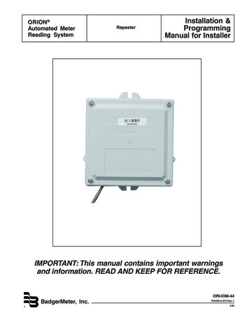
Section 1 General InformationPrinciples of OperationThe sample enters the Thermo Scientific Orion 2111LL sodium analyzer and passes throughinlet valve, bypass valve assembly, inlet filter, pressure regulator, flow meter, calibration shutoff valve and into the restrictor tubing. The sample then passes through the reagent manifoldinto a reagent bottle through a diffusion tubing assembly where pH adjustment takes place. ThepH adjusted sample then flows into the flow cell via the diverter valve, where air is introducedfrom the air pump to ensure proper mixing and fast response. The sample then flows into anatmospheric drain.2111LL Schematic8 Orion 2111LL Low Level Sodium AnalyzerThermo Scientific
General Information Section 1The sensing electrode responds logarithmically to changes in the sodium ion concentration.This response is described by the Nernst equation:E Eo 2.3 (RT/nF) log (C/Ciso)Where:E measured electrode potential, mV potential, when C equals Ciso, mVEoR ideal gas constantT temperature of sample, degrees Kn valence of ionic species ( 1 for sodium ion)F Faraday’s constantC effective sodium ion concentration (activity)Ciso concentration (activity) of sodium ion where potential E is temperature independent(isopotential point)The above equation indicates that the measured potential varies with both temperature and theconcentration of the ion of the interest. In order to eliminate error caused by fluctuations insample temperature, the 2111LL microprocessor constantly updates temperature correctionsfrom data supplied by the ATC probe.From the Nernst equation, the theoretical response of a sodium ion-selective electrode to a tenfold change in concentration at 25 C is 59.16 mV. This is referred to as the electrode slope (S).Most electrodes, however, do not exhibit a theoretical slope. Therefore, the analyzer iscalibrated to determine its actual value. Two standards are used to provide informationnecessary for the microprocessor to compute the actual slope and E0 for use during sampleanalysis.In order to eliminate interference from hydrogen ions, which can become significant whenmeasuring low levels of sodium, the 2111LL analyzer adjusts sample pH to approximately 11.This pH adjustment is accomplished by the patented passive-diffusion process wherein thesample passes through a length of tubing contained in the reagent bottle. The reagent diffusesthrough the tube wall and mixes with the sample, raising sample pH to approximately 11.Principles of CalibrationCalibration procedures for an analytical instruments are important and must be performedcarefully. The calibration procedure used in the Thermo Scientific Orion 2111LL analyzer is avariation of Double Known Addition (DKA) using ROSS electrode technology and patentpending flow cell technology in combination with the passive diffusion system. This method hasthe distinct advantages of being fast, easy, and accurate.Thermo ScientificOrion 2111LL Low Level Sodium Analyzer 9
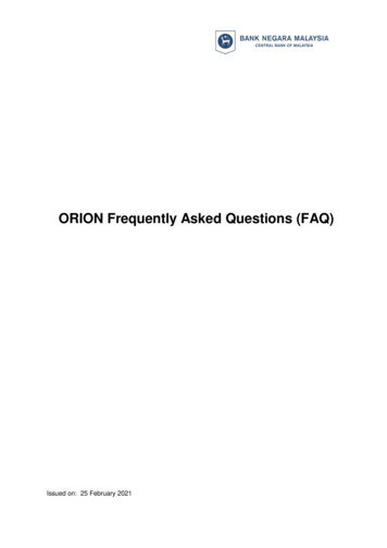
Section 1 General InformationDouble Known Addition (DKA)Before calibration begins, the diverter valve is turned to divert flow from the measure drain tothe re-circ tube, allowing the flow cell to fill.The two air valves serve dual purposes during the calibration sequence.The first function is to stop the airflow through the sample, and redirect the airflow to theheadspace of the flow cell. Thus, the flow cell is filled without causing air bubble disturbance inthe sensing tube. The second function ensures proper siphoning operation. The combination ofthese functions provides an accurate volume for calibration.At the first step of the DKA calibration the actual concentration in the sample is unknown. Theanalyzer measures the potential (Es) and stores this value in the microprocessor. A knownamount of standard 1 solution is added to the flow cell, which increases the concentration (Cs)with a corresponding known amount (dC1). During this process, air is pumped into the re-circtube, thoroughly mixing sample and standard in a closed-loop system. The new potential (E1) ismeasured and stored automatically when stability is reached. Adding standard 2, preferably 10times more concentrated than standard 1, increases the concentration (dC2) in the samplereservoir. Again, the new potential (E2) is measured and stored when stable. Now, we have thefollowing three unknowns:Es Eo S(Ts/298.15) log (Cs/Ciso)E1 Eo S(T1/298.15) log [(Cs dC1)/Ciso]E2 Eo S(T2/298.15) log [(Cs dC1 dC2)/Ciso]S is the Slope at 25 C (298.15 K)T is the temperature in Kelvin, measured when the potential E is measured.Es, E1, E2 have been determined during the calibration procedure. The microprocessor solvesthese three equations, to obtain the values of S and Eo. The calibration result is stored for useduring online monitoring to convert the measured potential and temperature in the sample intoconcentration values in either ppm or ppb.When the calibration is complete the flow cell drains as the sample flow returns. The flow cellvolume returns to the measurement level. After allowing approximately 30 minutes forconcentrated calibration solution to be flushed from the system, the 2111LL analyzer can beginsample measurement again.In addition to Double Known Addition (DKA), the 2111LL analyzer also allows the operator theability to perform an offline calibration.10 Orion 2111LL Low Level Sodium AnalyzerThermo Scientific
General Information Section 1Flow Cell Volume for DKAOffline CalibrationThe offline calibration feature of the 2111LL analyzer allows the operator to adjust the analyzerto values determined by alternate methods used in their laboratory such as elementalspectroscopy and ion chromatography.It is essentially a one point calibration. To perform offline calibration, a sample is taken from thebypass of the analyzer; the sample concentration value is stored in memory; the sample isanalyzed by an alternate method of choice; the previously stored reading is adjusted to the labmethod result; and the analyzer is then returned to the analysis mode. The term “offlinecalibration” refers only to the fact that a sample from 2111LL analyzer bypass is taken “offline”for laboratory analysis; in fact, no downtime is experienced during the procedure and theanalyzer remains online throughout.Blank CorrectionThe blank correction adds an offset to the measurement, and does not change the slope or Eovalue. The blank can be varied up to /- 1ppb of the sodium reading to match alternate analysisvalues.Thermo ScientificOrion 2111LL Low Level Sodium Analyzer 11
Section 1 General InformationFluidics Diagram12 Orion 2111LL Low Level Sodium AnalyzerThermo Scientific
General Information Section 1Fluidics Diagram (No Air Valves)GlossaryRefer to 2111LL schematic diagram.Inlet Valve – Accepts the sample stream via 1/4 inch NPTF connector. The operator mustsupply the sample with a pressure between 14 and 100 psig.Inlet Filter – 60 micron stainless steel filter that traps particulate matter in the sample stream.Bypass Valve – Used to redirect flow in the bypass system.Pressure Regulator – Adjusts flow on the incoming sample stream.Thermo ScientificOrion 2111LL Low Level Sodium Analyzer 13
Section 1 General InformationFlow Meter – Measures the sample flow rate (40 mL/minute nominal).Calibration Shut Off Valve – Used to stop the flow of sample from the flow meter to therestrictor tubing.Restrictor Tube Assembly – Used in conjunction with the pressure regulator to lowerdownstream pressure.Reagent Manifold – Directs the sample flow in and out of the reagent bottle assembly.Reagent Bottle Adapter Assembly – Connects the reagent bottle assembly to the manifold.Diffusion Tubing Assembly – Semi-permeable tubing through which reagent diffuses into thesample.Reagent Bottle – Contains a water soluble amine, which raises the sample pH toapproximately 11.Reagent Bottle Bracket – Secures the reagent bottle.Flow Cell – Contains the sodium sensing electrode, reference electrode and ATC probe.Diverter Valve – Allows the flow cell reservoir to fill during calibration by forming a closed-loopsystem.Re-circulation Tube – Tube through which sample (assisted by air) is pumped into the flowcell, used to mix solution in a closed-loop during calibration.Sodium Electrode – Senses sodium ions in the sample stream and produces an electricalpotential dependent on the sample concentration.Reference Electrode – Provides a constant reference potential and completes themeasurement circuit.Reference Electrode Filling Solution Bottle – Provides constant flow of electrolyte solutionthrough reference electrode for maximum stability.ATC Probe – Measures sample temperature and inputs data to microprocessor for automatictemperature compensation (ATC).Calibration Port – Allows introduction of standards to the sample reservoir during calibration.Air Pump – Used to mix the sample during both measurement and calibration.Right Air Valve – Adjusts airflow to the flow cell and controls airflow for mixing the sample.14 Orion 2111LL Low Level Sodium AnalyzerThermo Scientific
General Information Section 1Left Air Valve – Adjusts airflow to the flow cell and controls airflow for siphoning of the sample.LCD Display – Provides digital readout
Orion 2111LL Low Level Sodium Analyzer Thermo Scientific Principles of Operation The sample enters the Thermo Scientific Orion 2111LL sodium analyzer and passes through inlet valve, bypass valve assembly, inlet filter, pressure regulator, flow meter, calibration shut-off valve and into the restrictor tubing. The sample then passes through the .