Transcription
Technical informationSelecting Centrifugal Pumps
Copyright byKSB AktiengesellschaftPublished by:KSB Aktiengesellschaft,Communications (V5),67225 Frankenthal / GermanyAll rights reserved. No part ofthis publication may be used,reproduced, stored in or intro duced in any kind of retrievalsystem or transmitted, in anyform or by any means (electro nic, mechanical, photocopying,recording or otherwise) withoutthe prior written permission ofthe publisher.4th completely revised and ex panded edition 2005Layout, drawings andcompo sition:KSB Aktiengesellschaft,Media Production V51ISBN 3-00-017841-4
ContentsTable of contents 123Nomenclature.6Pump Types .8–9Selection for Pumping 23.5.23.5.33.6Pump Data.10Pump Flow Rate.10Developed Head and Developed Pressure of the Pump.10Efficiency and Input Power.10Speed of Rotation.11Specific Speed and Impeller Type.11Pump Characteristic Curves.13System Data.16System Head .16Bernoulli’s Equation.16Pressure Loss Due to Flow Resistances.18Head Loss in Straight Pipes.18Head Loss in Valves and Fittings.22System Characteristic Curve.26Pump Selection.28Hydraulic Aspects.28Mechanical Aspects.29Motor Selection.29Determining Motor Power.29Motors for Seal-less Pumps.31Starting Characteristics.31Pump Performance and Control.34Operating Point.34Flow Control by Throttling.34Variable Speed Flow Contol.35Parallel Operation of Centrifugal Pumps.36Series Operation.38Turning Down Impellers.38Under-filing of Impeller Vanes.39Pre-swirl Control of the Flow.39Flow Rate Control or Change by Blade Pitch Adjustment.39Flow Control Using a Bypass.40Suction and Inlet Conditions.41The NPSH Value of the System: NPSHa .41NPSHa for Suction Lift Operation.43NPSHa for Suction Head Operation.44The NPSH Value of the Pump: NPSHr.44Corrective Measures.45Effect of Entrained Solids.474Special Issues when Pumping Viscous Fluids.484.14.24.2.14.2.24.34.3.14.3.2The Shear Curve.48Newtonian Fluids.50Influence on the Pump Characteristics.50Influence on the System Characteristics.54Non-Newtonian Fluids.54Influence on the Pump Characteristics.54Influence on the System Characteristics.55
ContentsTables5Special Issues when Pumping Gas-laden Fluids.566Special Issues When Pumping Solids-laden Fluids.576.16.26.36.46.5Settling Speed.57Influence on the Pump Characteristics.58Influence on the System Characteristics.59Operating Performance.59Stringy, Fibrous Solids.597The Pump Installation Arrangements.61Pump Intake Structures.61Pump Sump.61Suction Piping.62Intake Structures for Tubular Casing Pumps.64Priming Devices.65Arrangement of Measurement Points.67Shaft Couplings.68Pump Nozzle Loading.69National and International Standards and Codes.698910Calculation Examples(for all equations numbered in bold typeface).71Additional Literature.79Technical Annex (Tables, Diagrams, Charts).80Tab. 1:Tab. 2:Tab. 3:Centrifigal pump classification.8Reference speeds of rotation.11Approximate average roughness height k for pipes.20Tab. 4:Inside diameter d and wall thickness s in mm and weight ofTab. 5:Tab. 6:Tab. 7:Tab. 8:Tab. 9:Tab. 10:Tab. 11:Tab. 12:Tab. 13:Tab. 14:typical commercial steel pipes and their water content.20Loss coefficients ζ for various types of valves and fittings.23Loss coefficients ζ in elbows and bends.24Loss coefficients ζ for fittings.24/25Loss coefficients ζ for adapters.25Types of enclosure for electric motors to EN 60 529 andDIN/VDE 0530, Part 5.30Permissible frequency of starts Z per hour for electric motors.30Starting methods for asynchronous motors.32Vapour pressure, density and kinematic viscosity of water atsaturation conditions as a function of the temperature.42Influence of the altitude above mean sea level on the annualaverage atmospheric pressure and on the correspondingboiling point .43Minimum values for undisturbed straight lengths of pipingat measurement points in multiples of the pipe diameter D.67
1Nomenclature1Nomenclature AAm2mAreaDistance between measuring point and pumpflangeam, mmWidth of a rectangular elbowBm, mmVertical distance from suction pipe to floorCvgpmFlow coefficient for valves, defined as the flowof water at 60 F in US gallons/minute at apressure drop of 1 lb/in2 across the valvecDResistance coefficient of a sphere in water flowcT(%)Solids content in the flowDm (mm)Outside diameter; maximum diameterDN(mm)Nominal diameterdm (mm)Inside diameter; minimum diameterdsm (mm)Grain size of solidsd50m (mm)Mean grain size of solidsFNForcefThrottling coefficient of an orificefHConversion factor for head (KSB system)fQConversion factor for flow rate (KSB system)fηConversion factor for efficiency (KSB system)gm/s2Gravitational constant 9.81 m/s2HmHead; discharge headHgeomGeodetic headHsmSuction liftHs geo mVertical distance between water level and pumpreference plane for suction lift operationHz geo mVertical distance between pump reference planeand water level for positive inlet pressureoperationHLmHead lossH0mShut-off head (at Q 0)IAElectric current (amperage)KDimensionless specific speed, type numberkmm, µmMean absolute roughnesskConversion factors kQ, kH, kη (HI method)3kvm /hMetric flow factor for valves, defined as theflow of water at 20 C in cubic metres per hourat a pressure drop of 1 barLmLength of pipeLsmStraight length of air-filled pipeMNmMomentNPSHr mNPSH required by the pumpNPSHa mNPSH availableNsSpecific speed in US unitsnmin–1 (rpm) Speed of rotations–1 (rev/s)nqmin–1Specific speed in metric unitsPkW (W)Power; input power
1NomenclaturepePN(bar) pbar (Pa)pbar (Pa)pbmbar (Pa)pLbar (Pa)pvbar (Pa)Qm3/s, m3/hqair%Qoffm3/hQonm3/hRm (mm)ReSmss’mmmTNmt CUmUmVBm3VNm3vm/swm/symmZ 1/hzzs,dmα δ ζη(%)ηPa sλ m2/s kg/m3τN/m2τfN/m2ϕψPressure in suction or inlet tankNominal pressurePressure rise in the pump; pressure differen tial(Pa N/m2)Pressure (Pa N/m2 10–5 bar)Atmospheric pressure (barometric)Pressure lossVapour pressure of fluid pumpedFlow rate / capacity (also in litre/s)Air or gas content in the fluid pumpedFlow rate at switch-off pressureFlow rate at start-up pressureRadiusReynolds numberSubmergence (fluid level above pump);immersion depthWall thicknessDifference of height between centre of pump impeller inlet and centre of pump suction nozzleTorqueTemperatureLength of undisturbed flowWetted perimeter of a flow sectionSuction tank volumeUseful volume of pump sumpFlow velocitySettling velocity of solidsTravel of gate valve; distance to wallSwitching cycle (frequency of starts)Number of stagesHeight difference between pump discharge andsuction nozzlesAngle of change in flow direction; opening angleAngle of inclinationLoss coefficientEfficiencyDynamic viscosityPipe friction factorKinematic viscosityDensityShear stressShear stress at yield pointTemperature factor; opening angle of a butter fly valve; cos ϕ: power factor of asynchronousmotorsHead coefficient (dimensionless head generatedby impeller)Indices, SubscriptsaAt outlet cross-section ofthe system; branching offBlReferring to orifice boredOn discharge side; at dis charge nozzle; flowingthroughdynDenoting dynamic com ponentAt the narrowest crossEsection of valves (Table 5)EAt suction pipe or bell mouth inleteAt inlet cross-section ofsystem, e. g. in suctionor inlet tankfReferring to carrier fluidHHorizontalinReferring to inlet flowKReferring to curvatureLReferring to lossesmMean valuemax Maximum valueminMinimum valueNNominal valueoptOptimum value; at bestefficiency point (BEP)PReferring to pumppReferring to pressureReduced, for cutdown imrpeller or impeller vanessOn suction side; at suc tion nozzlesReferring to solidsstatStatic componentsysReferring to system /installationtReferring to impellerprior to trimmingVVerticalwReferring to waterzReferring to viscous fluid0Basic position, referredto individual sphere1, 2, 3 Consecutive numbers;itemsI, IINumber of pumps oper ated
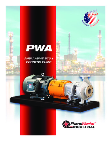
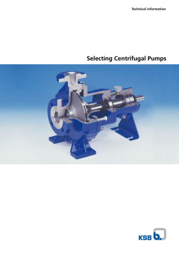
2Pump Types (Examples)2Pump Types– the position of the shaft (hori zontal / vertical),Other pump classificationfeatures include:Typical selection criteria forcentrifugal pumps are theirdesign data (flow rate or capac ity Q, discharge head H, speedof rotation n and NPSH), theproperties of the fluid pumped,the application, the place ofinstallation and the applicableregulations, specifications, lawsand codes. KSB offers a broadrange of pump types to meet themost varied requirements.– the pump casing (radial, e. g.volute casing / axial, e. g.tubular casing),– the mode of installation, whichis dealt with in section 7.1,– the number of impeller entries(single entry / double entry),– the type of motor (dry mo tor / dry rotor motor, e. g.submerged motor / wet rotormotor, e. g. canned motor,submersible motor).These features usually determinewhat a pump type or serieslooks like. An overview of typi cal designs according to classi fication features is given below(Table 1 and Figs. 1a to 1p).Main design features for classifi cation are:– the number of stages (singlestage / multistage),Table 1: Centrifugal pump classification– the nominal diameter (for thepump size, as a function ofthe flow rate),– the rated pressure (for thewall thickness of casings andflanges),– the temperature (for examplefor the selection of coolingequipment for shaft seals),– the fluid pumped (abrasive,aggressive, toxic fluids),– the type of impeller (radialflow / axial flow depending onthe specific speed),– the self-priming ability,Number of stagesSingle stageMultistageShaft positionHorizontalHoriz. Vertic.Casing designRadial Axial Radial Axial Stage casingVertical– the casing partition, the posi tion of the pump nozzles, anouter casing, etc.Impeller entries 1 2 1 1 2 1 1 1Motor type, Fig. 1.Dry (standardized)motorMagnetic driv
7 pe Pressure in suction or inlet tank PN (bar) Nominal pressure p bar (Pa) Pressure rise in the pump; pressure differential (Pa N/m ) p bar (Pa) Pressure (Pa N/m 0–5 bar) p b mbar (Pa) Atmospheric pressure (barometric)