Transcription
CTS Self-primingCentrifugal Pumpsedition 2016 rev 2Read this instruction manual carefully,before you install and operate the pumpCTS ICTS HWith 2900 rpm motor:With 2900 rpm motor:CTS I CC-22CTS H CC-22CTS I CE-22CTS H CE-22CTS I DD-40CTS H DD-40CTS I DF-40CTS H DF-40CTS I EF-55CTS H EF-55CTS I EG-55CTS H EG-55CTS I EF-75CTS H EF-75CTS I EG-75CTS H EG-75
CONTENTS1.0.GENERAL .50.1.Introduction.50.2.Warning symbols .50.3.Qualification and training of personnel .5INSTALLATION . 61.1.Operation principle .61.2.Receiving inspection .61.3.Storage .61.4.Foundation .61.5.Environment .71.6.Suction and discharge piping .71.6.1.Connection of discharge pipe . 71.6.2.Connection of suction pipe . 71.7.1.7.1.Protection . 81.7.2.Electrical safety . 81.7.3.Chemical hazard . 81.7.4.Dry running . 81.7.5.Noise level . 81.7.6.Temperature hazards . 81.7.7.Rotating parts. 81.7.8.Cleaning and disinfection . 91.8.Example of installation .91.9.Instruments.101.9.1.Electric power . 101.9.2.Optional instruments . 101.9.3.Thermometer . 101.10.2.Health and safety .8Motor connection .10OPERATION . 122.1.Start-up .122.1.1.Starting the pump . 122.1.2.Restarting after power shut-off . 132.2.Stopping the pump .132.3.Cleaning and disinfection .132.3.1.Cleaning procedure . 13IOM manual CTS self-priming pumps2
CONTENTS3.MAINTENANCE . 143.1.Inspections .143.2.Location of faults .153.3.Disassembly of the pump .163.3.1.3.4.Assembly of the pump.173.4.1.4.5.6.Disassembly procedure . 16Test run . 19SPARE PARTS . 204.1.Spare parts drawing .204.2.Spare parts list.204.3.Recommended spare parts .214.4.How to order parts.21DATA . 225.1.Pump code .225.2.Dimensions .235.3.Materials, data and limits .245.4.Mounting torques and dimensions of screws/nuts .245.5.Performance curves .25WARRANTY . 276.1.Returning parts .276.2.Warranty .276.3.Warranty form .29IOM manual CTS self-priming pumps3
CE CERTIFICATEIOM manual CTS self-priming pumps4
0.GENERAL0.GENERAL0.1.IntroductionCTS is an open impeller self-priming centrifugal pump, manufactured from stainless steelAISI 316L. CTS H with excellent electro polished surfaces, FDA approved seals, high finishand mechanical strength, meet the demands from food and sanitary applications, CTS I withAISI 316L chemical resistance and mechanical strength is a reliable choice.The self-priming feature allows to use the pump in applications where standard CT pumpsdo not prove useful. The CTS pump is capable of creating up to 4,5 m of suction lift.With proper attention to maintenance, CTS pumps will give efficient and trouble freeoperation. This instruction manual will familiarise operators with detailed information aboutinstalling, operating and maintaining the pump.0.2.Warning symbolsThe following warning symbols are present in this instruction manual. This is what they say:This symbol stands next to all safety instructions in this instruction manualwhere danger to life and limb may occur. Observe these instructions andproceed with utmost caution in these situations. Inform also other users of allsafety instructions. In addition to the instructions in this instruction manual, thegeneral safety and accident prevention regulations must be observed.This signal stands at points in this instruction manual of particular importancefor compliance with regulations and directives, for correct work flow and for theprevention of damage to and destruction of the complete dampener or itssubassemblies.This symbol signals possible danger caused by the presence of electric fields orlive wires.0.3.Qualification and training of personnelThe personnel in charge of installation, operation and maintenance of the pumps weproduce must be qualified to carry out the operations described in this manual. Tapflo shallnot be held responsible for the training level of personnel and for the fact that they are notfully aware of the contents of this manual.IOM manual CTS self-priming pumps5
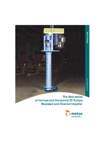
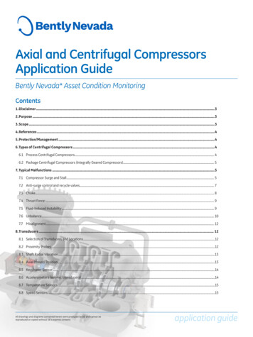
1.1.1.1.INSTALLATIONINSTALLATIONOperation principleIn order for the priming action to be achieved, the pump casing has to be filled with liquidto a level above the impeller (1). When the pump starts its operation, it is slowly sucking outthe air from the suction line thus creating negative pressure and lifting the product. The airis mixed with the liquid in the pump casing (2). In order to achieve the self-priming capability,the shut-off / regulation valve on the discharge side must be opened. The air escapes thecasing through the discharge line while the liquid returns to the impeller as it has higherspecific gravity than the liquid/air mixture. This process continues until the suction line iscompletely free of air and the pump can operate as a standard centrifugal pump (3).11.2.23Receiving inspectionAlthough precaution is taken by us when packing and shipping, we urge you to carefullycheck the shipment on receipt. Make sure that all parts and accessories listed on the packinglist are accounted for. Immediately report any damage or shortage to the transport companyand to us.1.3.StorageIf the equipment is to be stored prior to installation, place it in a clean location. Do notremove the protective covers from the suction and discharge which have been fastened tokeep pump internals free of debris. Clean the pump thoroughly before installation.When in storage, turn the shaft by hand at least twice per week.1.4.FoundationThe pump-motor unit must stand on and be fixed to a sufficiently rigid structure that cansupport the entire perimeter on which the unit stands. The foundation on a firm bottom isthe most satisfactory. Once the pump is in position, adjust level with metal shims betweenthe feet and the surface on which it stands. Check that the feet of the pump motor unit standwell on each of them. The surface on which the foundation stands must be flat andhorizontal. If the unit is fitted on a steel structure, make sure that it is supported so that thefeet do not warp. In any case, it is advisable to fit some anti-vibration rubber pieces betweenIOM manual CTS self-priming pumps6
1.INSTALLATIONthe pump and the brickwork. The motor needs an additional stand as its level is higher thanthat of the pump casing. As an option the pump can be ordered with feet for the motor. Forclose-coupled type, pump motor alignment is not required.1.5.Environment There should be enough space in the vicinity of the pump in order to operate, maintainand repair it. The area in which the pump is operated, must be sufficiently ventilated. Excessivetemperature, humidity or dirt may affect the pump operation’/ Behind the cooling fan of the motor there must be sufficient room for the hot air toescape the motor.1.6.Suction and discharge pipingA pump is generally part of a piping system that can include a number of components suchas valves, fittings, filters, expansion joints, instruments, etc. The way the piping is arrangedand the positioning of the components has a great influence on the operation and thelifetime of the pump. The pump cannot be used as a support for the components connectedto it.The flow of liquid from the pump must be as even as possible. It is advisable to avoid anytight bends or drastic reductions of diameters that may cause flow resistance in theinstallation. In case of diameter reduction, it is advisable to use appropriate conicalreductions (possibly eccentric on suction side and concentric on discharge side) at changesof diameter and at a minimum distance from pump connections of five diameters.NOTE! The pump casing is designed for maximal work pressure of 3 bar (fo
Whenever the pump is to be used for pumping a different liquid, it is essential to clean the pump beforehand in order to avoid any possible reaction between the two products. 1.7.4. Dry running Do not start nor carry out running tests before filling the pump with liquid. Always avoid dry operation of the pump. Start the pump when it is .