Transcription
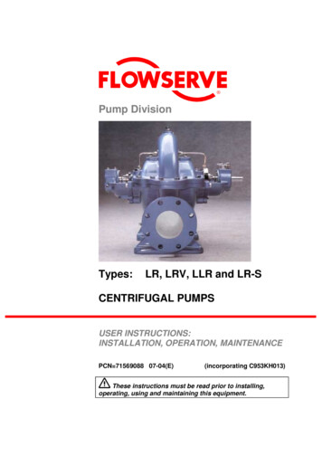
Pump DivisionTypes:LR, LRV, LLR and LR-SCENTRIFUGAL PUMPSUSER INSTRUCTIONS:INSTALLATION, OPERATION, MAINTENANCEPCN 71569088 07-04(E)(incorporating C953KH013)These instructions must be read prior to installing,operating, using and maintaining this equipment.
LR, LRV, LLR and LR-S USER INSTRUCTIONS ENGLISH 71569088 07-04 CONTENTSPAGEPAGE1 INTRODUCTION AND SAFETY . 41.1 General. 41.2 CE marking and approvals . 41.3 Disclaimer. 41.4 Copyright . 41.5 Duty conditions . 41.6 Safety . 51.7 Warning labels summary. 81.8 Specific machine performance . 81.9 Noise level . 96 MAINTENANCE. 226.1 General . 226.2 Maintenance schedule. 236.3 Spare parts. 256.4 Recommended sparesand consumable items . 256.5 Tools required. 256.6 Fastener torques . 266.7 Renewal clearances . 266.8 Disassembly. 266.9 Examination of parts. 286.10 Assembly. 292 TRANSPORT AND STORAGE.102.1 Consignment receipt and unpacking.102.2 Handling .102.3 Lifting.102.4 Storage .102.5 Recycling and end of product life.103 PUMP DESCRIPTION.113.1 Configurations.113.2 Name nomenclature.113.3 Design of major parts .113.4 Performance and operating limits .124 INSTALLATION .124.1 Location .124.2 Part assemblies .124.3 Foundation.124.4 Grouting.134.5 Initial alignment .134.6 Piping .144.7 Final shaft alignment check .174.8 Electrical connections .174.9 Protection systems.175 COMMISSIONING, START-UP, OPERATIONAND SHUTDOWN .185.1 Pre-commissioning procedure .185.2 Pump lubricants .195.3 Direction of rotation .205.4 Guarding.205.5 Priming and auxiliary supplies .205.6 Starting the pump.205.7 Running the pump.215.8 Stopping and shutdown .225.9 Hydraulic, mechanical and electrical duty .227 FAULTS; CAUSES AND REMEDIES . 348 PARTS LISTS AND DRAWINGS . 368.1 Sectional drawings – LR single entryimpeller, grease lubricated, gland packed(pump sizes 2.5LR-10 and 2.5LR-13 only) . 368.2 Sectional drawings – LR double entryimpeller, grease lubricated, gland packed . 388.3 Sectional drawings – LLR greaselubricated, gland packed . 408.4 Sectional drawings – LR-S double entryimpeller, grease lubricated, gland packed . 428.5 Sectional drawings – LRV double entryimpeller, grease lubricated thrust bearing,component mechanical seal, SiC bearing. 448.6 Interchangeability charts. 468.7 General arrangement drawing . 479 CERTIFICATION . 4710 OTHER RELEVANT DOCUMENTATIONAND MANUALS . 4710.1 Supplementary User Instructions . 4710.2 Change notes . 4710.3 Additional sources of information . 47Page 2 of 48
LR, LRV, LLR and LR-S USER INSTRUCTIONS ENGLISH 71569088 07-04 INDEXPAGEPAGEAdditional sources (10.3).47Alignment of shafting (4.3, 4.5 and 4.7)Assembly (6.10) .29ATEX marking (1.6.4.2) . 7CE marking and approvals (1.2) . 4Certification (9).47Change notes (10.2).47Clearances (6.7, Renewal clearances) .26Commissioning and operation (5) .18Compliance, ATEX (1.6.4.1) . 6Configurations (3.1).11Consumable items (6.4) .25Copyright (1.4) . 4Design of major parts (3.3) .11Direction of rotation (5.3) .20Disassembly (6.8) .26Disclaimer (1.3) . 4Dismantling (6.8, Disassembly) .26Drawings (8).36Duty conditions (1.5) . 4Electrical connections (4.8) .17End of product life (2.5) .10Examination of parts (6.9) .28Fastener torques (6.6).26Faults; causes and remedies (7).34Forces and moments (4.6.3).15Foundation (4.3).12General arrangement drawing (8.8) .47General assembly drawings (8) .36Grouting (4.4).13Guarding (5.4).20Handling (2.2) .10Hydraulic, mechanical and electrical duty (5.9) .22Inspection (6.2.1 and 6.2.2) .23Installation (4) .12Interchangeability charts (8.6 and 8.7) .46Lifting (2.3).10Location (4.1) .12Lubrication (5.1.1, 5.2 and 6.2.3)Lubrication schedule (5.2.4) .19Maintenance (6) .22Maintenance schedule (6.2) .23Name nomenclature (3.2).11Nameplate (1.7.1) . 8Operating limits (3.4.1) .12Options (8) .36Ordering spare parts (6.3.1) .25Part assemblies (4.2) .12Parts lists (8) .36Performance (3.4) .12Piping (4.6) .14Pre-commissioning (5.1) . 18Priming and auxiliary supplies (5.5). 20Protection systems (4.9) . 17Reassembly (6.10, Assembly). 29Receipt and unpacking (2.1) . 10Recommended fill quantities (see 3.4.2) . 12Recommended grease lubricants (5.2.2). 19Recommended oil lubricants (5.2.1). 19Recommended spares (6.4). 25Recycling (2.5) . 10Renewal clearances (6.7) . 26Replacement parts (6.3 and 6.4). 25Running the pump (5.7) . 21Safety action (1.6.3). 5Safety markings (1.6.1). 5Safety, protection systems (1.6 and 4.9)Sectional drawings (8) . 36Sound pressure level (1.9, Noise level) . 9Sources, additional information (10.3) . 47Spare parts (6.3). 25Specific machine performance (1.8). 8Starting the pump (5.6) . 20Stop/start frequency (5.7.6). 22Stopping and shutdown (5.8) . 22Storage, pump (2.4). 10Storage, spare parts (6.3.2) . 25Supplementary manuals or information sources . 47Supplementary User Instructions (10.1) . 47Tools required (6.5) . 25Torques for fasteners (6.6). 26Trouble-shooting (see 7). 34Vibration (5.7.5) . 21Warning labels (1.7.2). 8Page 3 of 48
LR, LRV, LLR and LR-S USER INSTRUCTIONS ENGLISH 71569088 07-04 1 INTRODUCTION AND SAFETYand Approvals. To confirm the Approvals applyingand if the product is CE marked, check the serialnumber plate markings and the Certification. (Seesection 9, Certification.)1.1 GeneralThese Instructions must always be keptclose to the product’s operating location ordirectly with the product.Flowserve products are designed, developed andmanufactured with state-of-the-art technologies inmodern facilities. The unit is produced with greatcare and commitment to continuous quality control,utilising sophisticated quality techniques, and safetyrequirements.Flowserve is committed to continuous qualityimprovement and being at service for any furtherinformation about the product in its installation andoperation or about its support products, repair anddiagnostic services.These instructions are intended to facilitatefamiliarization with the product and its permitted use.Operating the product in compliance with theseinstructions is important to help ensure reliability inservice and avoid risks. The instructions may nottake into account local regulations; ensure suchregulations are observed by all, including thoseinstalling the product. Always coordinate repairactivity with operations personnel, and follow all plantsafety requirements and applicable safety and healthlaws and regulations.These instructions should be read prior toinstalling, operating, using and maintaining theequipment in any region worldwide. Theequipment must not be put into service until allthe conditions relating to safety, noted in theinstructions, have been met.1.2 CE marking and approvalsIt is a legal requirement that machinery andequipment put into service within certain regions ofthe world shall conform with the applicable CEMarking Directives covering Machinery and, whereapplicable, Low Voltage Equipment, ElectromagneticCompatibility (EMC), Pressure Equipment Directive(PED) and Equipment for Potentially ExplosiveAtmospheres (ATEX).Where applicable, the Directives and any additionalApprovals, cover important safety aspects relating tomachinery and equipment and the satisfactoryprovision of technical documents and safetyinstructions. Where applicable this documentincorporates information relevant to these Directives1.3 DisclaimerInformation in these User Instructions is believed tobe reliable. In spite of all the efforts of FlowservePump Division to provide sound and all necessaryinformation the content of this manual may appearinsufficient and is not guaranteed by Flowserve asto its completeness or accuracy.Flowserve manufactures products to exactingInternational Quality Management System Standards ascertified and audited by external Quality Assuranceorganisations. Genuine parts and accessories havebeen designed, tested and incorporated into theproducts to help ensure their continued product qualityand performance in use. As Flowserve cannot testparts and accessories sourced from other vendors theincorrect incorporation of such parts and accessoriesmay adversely affect the performance and safetyfeatures of the products. The failure to properly select,install or use authorised Flowserve parts andaccessories is considered to be misuse. Damage orfailure caused by misuse is not covered by theFlowserve warranty. In addition, any modification ofFlowserve products or removal of original componentsmay impair the safety of these products in their use.1.4 CopyrightAll rights reserved. No part of these instructions maybe reproduced, sto
THE PUMP IS OPERATIONAL DRAIN THE PUMP AND ISOLATE PIPEWORK BEFORE DISMANTLING THE PUMP The appropriate safety precautions should be taken where the pumped liquids are hazardous. FLUORO-ELASTOMERS (When fitted.) When a pump has experienced temperatures over 250 ºC (482 ºF), partial decomposition of fluoro-elastomers (example: Viton) will occur. In this