Transcription
EXAMENSARBETE INOM SAMHÄLLSBYGGNAD,AVANCERAD NIVÅ, 30 HPSTOCKHOLM, SVERIGE 2016Parametric BIM: EnergyPerformance Analysis UsingDynamo for RevitTASSOS MOUSIADISSINAN MENGANAKTHSKOLAN FÖR ARKITEKTUR OCH SAMHÄLLSBYGGNAD
Master Thesis no 447www.kth.se
Parametric BIM: Energy PerformanceAnalysis Using Dynamo for RevitTassos MousiadisSinan MenganaOctober 2016Master Thesis no 447
PrefaceThis thesis aims to encourage university students to explore more about parametricdesigning and its potential in university levels in Sweden. As there is barely anymaster thesis-es written about this topic, we took it upon our self to investigate thepossibilities of BIM. We would like to Thank our examiner Kjartan Gudmundsson,for supporting and pushing us toward the right path. And we would also like tothank our school, KTH, for the wonderful years and education we received.i
AbstractDue to the rapid development of technology, the AEC industry in Sweden havebeen struggling to string along it. The demand from authorities to use BIM in theindustry are increasing and the respond from companies are minimal. The buildingprocess uses to be spanned over several phases and the early design phase is wherefocus is lied on mostly in this thesis. Here can several actors as architects, engineersetc. be involved. Lack of communication and lack of coordination between the partshave an important impact on the outcome and therefore BIM was developed. In theearly designing phase, the project takes it shape and approximated calculations andanalysis have to made. Usually the results from the early design phase differ from theanalytical analysis that are made later and the costs of projects increases. However,many new tools have come along the way with that development which makes itpossible to make energy optimization an even more efficient practice. Therefore, thisthesis has been chosen to investigate the different energy possibilities and outcomesduring the early design stage, in the aspect of daylight and energy simulations. Asimple test building was constructed in Stockholm, Sweden. The building is formedin a way that allows various material parameters to be altered in order to study theimpacts of the annual energy distribution. This thesis will shed more light on why itis important to develop the methods of energy simulations in the early design phase,and it’s done by using the latest state of the art tools. A newly developed VPL toolnamed Dynamo together with the design tool Autodesk Revit and Green BuildingStudio is used in the simulation process. A script will be coded in the Dynamotool that will determine and allow the parameter variations of the building model inRevit. A comparison of 4 different case studies is graphically presented at the end.Even though the result was quite expected, the aim of this thesis was rather to serveas an example of how the tools of Dynamo and Revit can successfully coop-orate.ii
aryiii1 Introduction1.1 Background . . . . . . . . . . . . . .1.1.1 Building Construction Phases1.1.2 Early Design Phase . . . . . .1.2 Problem Formulation . . . . . . . . .1.3 Purpose . . . . . . . . . . . . . . . .1.4 Limitations . . . . . . . . . . . . . .2 Theory2.1 General about BIM . . . . . . . . . . .2.1.1 BIM-model . . . . . . . . . . .2.1.2 Benefits of BIM . . . . . . . . .2.2 Parametric Modeling . . . . . . . . . .2.2.1 A Brief History . . . . . . . . .2.2.2 Parametric Design of Buildings2.2.3 Parametric Modeling for Energy2.2.4 Visual Programming . . . . . .2.3 Design Tools . . . . . . . . . . . . . . .iii. . . . . . . . . . . . . . . . . . . . . . . . .Analysis. . . . . . . . .1115566.881111141415161718
2.42.3.12.3.22.3.3GreenAutodesk Revit . . . . . .Dynamo . . . . . . . . . .The Anatomy of DynamoBuilding Studio . . . . . .3 Methodology3.1 Model Geometry . . .3.2 Work process . . . . .3.3 Dynamo . . . . . . . .3.4 Green Building Studio4 Results4.1 Model4.1.14.1.24.1.34.1.4.of Procedure . . . . . . . . . . . . . . . . . .Height Parametrisation . . . . . . . . . . . .Width Parametrisation . . . . . . . . . . . .House Orientation Parametrisation . . . . .Amount of Window panels Parametrisation.18192021.2323262731.3333343536375 Conclusions and Discussion396 Future Work41References43Appendices44A Appendix45iv
List of Figures1.11.21.3Energy usage of the building sector of Sweden 1971-2013, TWh (Energimyndigheten 2015) . . . . . . . . . . . . . . . . . . . . . . . . . .The planning stage (Cpu.net 2013) . . . . . . . . . . . . . . . . . . .Sharing the BIM model through IFC (Graphisoft 2016) . . . . . . .2.12.22.32.42.52.6224The linear work flow in the building process (House 2015a) . . . .The ability to impact the building process (House 2015a) . . . . .Earlier work-flow building process (House 2015a) . . . . . . . . . .The ability to impact the work proces with BIM (House 2015b) . .Some of the Benefits of BIM (Calvert 2013) . . . . . . . . . . . . .Leaning building in Abu Dhabi designed with parametric modelingtool. (Evob 2015) . . . . . . . . . . . . . . . . . . . . . . . . . . .2.7 The movie Tron from 1982. (Tested 2015) . . . . . . . . . . . . . .2.8 One way a wall can look like (Grasshopper 2012) . . . . . . . . . .2.9 Program flow in Dynamo . . . . . . . . . . . . . . . . . . . . . . . .2.10 Anatomy of the Nodes . . . . . . . . . . . . . . . . . . . . . . . . . 9. 9. 10. 11. 526282930303132The first Revit model . . . . . . . . . . . . . . . . . .Average surface of the Revit model . . . . . . . . . .Revit model specifications . . . . . . . . . . . . . . .Dynamo and Revit collaboration . . . . . . . . . . .Dynamo script code . . . . . . . . . . . . . . . . . . .Dynamo nodes . . . . . . . . . . . . . . . . . . . . .Dynamo nodes . . . . . . . . . . . . . . . . . . . . .Dynamo nodes in-depth . . . . . . . . . . . . . . . .The Building Performances Factors in Dynamo RevitHeating Load Charts in Dynamo Revit . . . . . . . .a.
3.11 Building simulation list in GBS . . . . . . . . . . . . . . . . . . . . . 324.14.24.34.44.5Dynamo parametrizationWindow Height . . . . .Window Width . . . . .Window Orientation . .Window Panels . . . . .work-flow. . . . . . . . . . . . . . . . . . . . .A.1A.2A.3A.4Orientering . . . . . . . . . . .Window Panels ParametrizationFönsterbredd . . . . . . . . . .Fönsterhöjd . . . . . . . . . . .b.3435363738.45454646
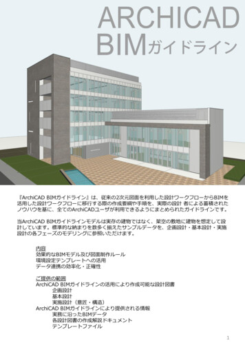
1. IntroductionThis introduction chapter will present the background to the research as well as topresent the research question, the purpose and the definitions.1.11.1.1BackgroundBuilding Construction PhasesThere is no construction project similar to another, but they all share some commoncharacteristic traits. These traits together construct the building process and generally include planning, development and a implementation of the project. These canfurther be divided into different stages regarding the whole lifetime of the buildingthat is to be constructed. According to statistics, the building environment accountsfor a large portion (about 1/3 part) of the country’s total energy consumption. Thebuilding electricity production in 2015 was the second highest annual production ofall times in Sweden (Energimyndigheten 2016).1
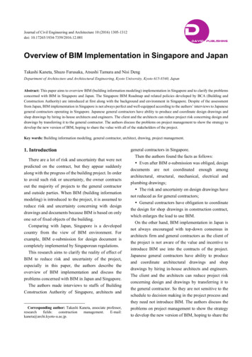
Figure 1.1: Energy usage of the building sector of Sweden 1971-2013, TWh (Energimyndigheten 2015)Due to these concerns, there have been increased demands in regards of energyand environmental aspects in construction planning in Sweden that have been developed in the past late years. Resources and costs have to be reduced in order toaccomplish the requirements that needs to be met. The demands for a sustainablesociety comes from both the owners, authorities, companies and the society itself(Regeringskansliet 2014).Figure 1.2: The planning stage (Cpu.net 2013)During the building process and in the planning stage, the authorities of a landscapeare responsible to take decisions if they consider that the landscape have possibilities2
to be exploited. Authorities creates a layout plan that works as a guidance for theirdecision making when contractors seek permission to perform a project. A layoutplan sets in a rough way the rules of how to exploit the land, and its descriptiongoverns how and where the buildings can be constructed. A zoning plan is latercreated in parts of the layout plan where exploiting possibilities exist. When decisionis taken to build in accordance to the zoning plan, the project gets its first shape inthe idea and baseline phase. The actors in this early phase are working with eachother in order to please both the authorities demand and the landscape owners.The important part in this phase is that it works as a spine for the entire projectwhere a lot of simple analysis can be done. This thesis will work on investigating onsome of these analysis, like for example the optimal orientation of the building, thesize of the windows. These studies will take place in the later sections. When allthe studies needed are finished, they are assembled in a building program with allconditions and requirement for the construction. As a final step in this phase thearchitect makes some preliminary sketches for different alternatives.After the first ideas and sketches are made, everything has to be designed in moredetails. This is governed in the design phase where architects, engineers and projectmanagers are all involved in the processing of the system documents. These document contains of drawings from all parts and technical descriptions which showsand describes the construction. Further on, everything has to be designed in astricter detailing, such as the positioning of windows, which types they are, howmuch lighting they produce, what nail dimensions is needed and so forth. In thisway all participants in the ongoing building process takes information from the construction in a more detailed level. Moreover, in this phase the management planningis made before continuing to the next phase to sustain budget for the project andto tackle some quality and environmental goals.From the documentation that is produced in the design phase the client makes anenquiry to contractors with information about what needs to be performed by eachcontractor. The enquiry that is turned over to the contractors should consist of atechnical part that describes how the building have to look like when it is finishedand an administration part that describes how the work have to be performed andthe conditions that is valid during that process. The contractor then makes a costcalculation for the work and leaves a proposal to the client in which he choose themost appropriate proposal or the one with lowest price. In the decision making3
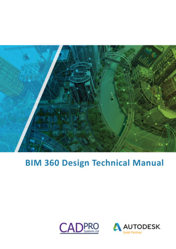
for the most appropriate proposal the clients usually take decisions regarding toquality, environment price for building and operation of the facilities. The client hasthe possibility to have one or several contractors. Something that is more commontoday is that the clients choose only one contractor before the design phase thatmanages all work. The contractor may in some cases engage other contractors tomanage parts that the general contractor is not fit to take care of in the project.When the client and the contractors comes to an agreement the building schedulecan begin. In this phase many different participants are involved such as the projectmanagers, electricians, constructions workers and all the actors involved. The workers need information on how the building will look like and how everything shouldbe constructed. This is usually extracted from a CAD model that is created througha IFC bridge to all the other software.Figure 1.3: Sharing the BIM model through IFC (Graphisoft 2016)4
1.1.2Early Design PhaseSignificant amount of the society’s energy consumption is due to buildings and totackle the environmental demands the EU and Swedish authorities have set goals toreduce building’s energy demands. The goal is to reduce the energy consumptionby 20 percent until year 2020 and by 50 percent until year 2050 Boverket 2015.The vision is to converge towards near zero energy consuming housing. During abuildings whole lifespan, the proportions for energy consumption are divided notonly in the period of the building service time but also on the construction stage.The production of material, the transportation and so forth make a big part of costs.In the early design phase designers are facing critical decisions and often have lack ofintuition about the right decisions that have great impact on the buildings in laterstages. Numerous researchers have shown that the earlier right decisions are madein the design process, the fewer the changes to these decisions will be at later stages.By this potential for reducing the building’s environmental impact is greater. Thiscould be achieved by choosing material on a smarter way or by optimizing the shapeand orientation of the building for example.1.2Problem FormulationThe development of technology in the building construction sector have been goingfast forward in the latest years. This has forced many of the older programs todevelop in order to satisfy the new required demands. The designers been forcedto work with 2D drawings, but as the digital world has kept progressing forward,3D modelling have slowly been taking over with an availability to 4D or 5D modelswhere cost and time can be considered. In addition to this, new tools have alsobeen created to be used as third party programs for optimization purposes. Thearchitects, project managers, installation and construction consultants all work indifferent software and have their own models. Afterwards changes in the modeloften creates several issues and errors that can lead to prolonging the project timeor increasing the costs. These issues in the early design phase are counteractedby using conceptual modeling tools such as in Revit or in Rhino. The conceptualmodeling software often makes simpler and more general simulations that gives anapproximation of the outcome later in the process. For example, the buildings sun5
energy distribution during a whole year or an approximation of the most optimalwindow glazing. Lastly, the latest addition among all modeling tools is the VPL(Virtual Programming Language) software. VPL software exists as a plug in or asa third party tool to the modeling software and creates the possibilities to take themodeling to a next level. The Architects can use a lot of programming and scriptingto create more complex models that normally is not possible in the already existingtools. This allows more flexibility to the other actors in the project by allowingthem to adjust more parameters in order optimize the model even further.1.3PurposeResearch on optimized parametrization in other countries has reached a much furtherstage than here in Sweden. Despite Sweden’s good potential in digitalization andcomputing development, it has not yet managed to achieve as rapid advances inenergy-smart solutions in comparison to countries like the US or China. The lackof researches on this has paved the way for more thesis on this subject. The aim ofthis work has been to investigate the advantages of using Revit as a single designtool platform while having the possibility of optimizing building models using plugin extensions such as Dynamo and Green Building Studio. By using Revit as thecentral design tool, the results and benefits of BIM can in an early stage be evaluated.The hard line goal is to illustrate the feasibility of implementing these middle wareplugins during the early stages of the building and to also present the enhancedbenefits when it comes to team collaboration and time saving aspects. The goal isalso to evaluate the practicability for people with little to no knowledge to use thesetools by presenting some examples of energy analysis later in thesis. The research ofthis subject also paves the way for more studies that can develop this branch evenfurther. This will be discussed more on the later chapters.1.4LimitationsDue to the lack of research done on this topic, a lot of time have been spent onfamiliarizing with the third party tool that has been paired with the Revit application. VPL is still on its early development and has yet to be fully explored and the6
full functionality of dynamo is limited since the program is still in its beta stage.Only architects have used these programs as aid to design complex shapes and nostudies have been found in optimization purpose for the designers.Therefore, this study can be seen as a groundbreaking research to assist students oremployees in the building industry. The complexity of the models has been limitedin order to prevent an extensive calculation time when optimizing for higher equalitymodels. And lastly, the aim of the study is restricted to research analysis done inthe early design phase.7
2. TheoryThe Terminology chapter will reflect the theory used.2.1General about BIMBIM which stands for Building Information Modeling is a new, modern and revolutionizing approach of design and documentation of building projects. With BIMtechnology one can create one or several accurate geometrical models and assigninformation that will support the construction and management activities duringall project phases. The most impressive about BIM though, is the coordinationbetween all participators of the project. These can be the client, the architect, theengineer, the contractor, consultants, fabricators and operators. With BIM there isa transparency in the project that makes it possible to all participants to take partof results or insight on the different processes during all project phases. The keygoals of this method is to create wider flexibility and to accommodate more rapidchanges during the process. The question is, what is so special about BIM comparedto a traditional work flow? A common headache for the consultant is when tryingto find clashes. Engineers, architects and builders are all gathered together withtheir respective drawings and have by overlaying the drawings to find where objectare intersecting and where they shouldn’t. This is very common in the constructionprocesses and the occasion for this i the linear work flow that is used.8
Figure 2.1: The linear work flow in the building process (House 2015a)When using BIM, the entire project can be designed, managed and executed allin one central model. The biggest flaw in the traditional process is the lack ofcommunication from the contributing parts in the project. The result of this maycause conflicts and problems later on the project leading to changes that needs tobe changed, which is a costly procedure.Figure 2.2: The ability to impact the building process (House 2015a)However, these changes can be avoided by adapting an integrated design approachwhere all the coordinates are started during the initial phase of the design process.This is achieved by front loading the project and allowing all the parties to be on thesame page from the very start. This creates opportunities to be much more efficientwith time planning, create coupled systems that work together and ultimately reduce9
the need for costly changes later down the road. All this is achieved by using abuilding information model, which is a 3D model that incorporates all the essentialcomponents that makes up for a building. It is like a cloud-stored text document thatallows multiple users to edit, but through a 3D model that every actor works through.It’s called an integrative design process that is comparable to the traditional processand allows all the participants to contribute to the project from start.Figure 2.3: Earlier work-flow building process (House 2015a)10
Figure 2.4: The ability to impact the work proces with BIM (House 2015b)2.1.1BIM-modelThe main CAD tools used until some years ago have all been plotted 2D drawings.With the introduction of the 3D models, a lot more complex surfacing tools havebeen added to allow more advanced geometries. Today’s BIM tools are able topresent the plot drawing in multiple angles or view intersections by converting the2D model into a 3D model. An important detail in the process is as mentioned beforethat when the model is created, all involved parties are involved in the creatingprocess. The BIM model is a virtual image of the real case scenario and all theinformation about the life cycle of the building are therefor included in it. Theinformation is both the physical part, the logical composition of the objects and thebuilding itself.2.1.2Benefits of BIMThere is plenty of benefits when using BIM in a project, but the most importantaspect of BIM comes during the early design stage where many important decisionsare being taken. The early stages of every building process is seen as the foundationof the whole project. A more planned and a well thought beginning often resultsin less errors during the whole building work development. The biggest proportion11
of benefits are actually related to the design of the model. Instead of generatingthe model from multiple 2D views the 3D model is generated by designing directlywith BIM software. The design may in that way be visualized earlier and moreaccurate. At any stage of the design, accurate and consistent 2D drawings can beextracted for any set of objects or a specified view of the project. This lead to areduction of time and number of errors associated to the generation of the drawingsfor all disciplines. If changes on the model are required, new and fully consistentdrawings can be produced as soon as the model is modified. The errors due tolack of communication can also be reduced by the possibility of earlier collaborationof multiple design disciplines. The collaboration with drawings is more inherentand difficult than using one or several coordinated 3D models where changes can bemanaged more controlled. Also with earlier collaboration, insight to design problemsis given and the designer has the possibilities to improve the model. With the earlier3D visualizations, it is also possible to make better cost estimations due to the betterquantification of areas and material. An example to this is the cost reduction dueto energy analyses that can be executed in early stages thanks to the possibility tolink the BIM model to the simulation tools. Usually with 2D design one have towait until the end of the design stage to make an energy evaluation only as a checkor a regulatory requirement. This reduces the possibilities to modify the modelsand improve the energy performance of the building. By linking the model to thesimulation tools, modifications and improvements are made early in the process andtherefore the outcome is a better building quality is obtained.12
Figure 2.5: Some of the Benefits of BIM (Calvert 2013)13
2.2Parametric ModelingParametric modeling is not something new and was originally developed in the 80’sfor manufacturing. The objects that are represented have not fixed geometry andproperties. Instead the geometry and non-geometric properties are represented withparameters and rules that determine the geometries and properties. The parametersand rules can be expressed in terms of other geometries and properties so that whenthese changes from the user the parameters change in their turn. Now complexgeometries that were simply impractical or non-possible in the past, can be modeledthanks to parametric objects. In architecture and construction, BIM software companies e.g. Autodesk, have decided to create a set of base building object classesthat the users may modify, add feature or extend before using them.Figure 2.6: Leaning building in Abu Dhabi designed with parametric modeling tool.(Evob 2015)2.2.1A Brief HistoryIn 1960 the research about modeling 3D geometry gained big importance because ofits potential in different areas such as movies, architectural and engineering design,games and so forth. The first computer graphic film, Tron (1982) was an accomplishment thanks to the ability of representing compositions of polyhedral forms for14
viewing that was developed in late 1960s. The design of pictures with these polyhedrons were limited and it was possible to produce practical 3D models with solidelement first after 1973. Different approaches had been developed by scientist andBIM architectural design tools today, all grew up from the object-based parametriccapabilities that was developed.Figure 2.7: The movie Tron from 1982. (Tested 2015)2.2.2Parametric Design of BuildingsIn parametric design, instead of designing an instance of a building element likea particular wall or door, a designer first defines an element class or family whichdefines some mixture of fixed and parametric geometry, a set of relations and rulesto control the parameters by which element instances can be generated. As anexample one element class or family is windows. Fixed geometry or parametricgeometry are such as width, height, duct space and so on. An instance is a way torealize an object and by the rules and relations different realizations of a windoware possible. These rules and relations may be such as attached to, parallel to, offsetfrom and so forth. With these relations an instance may vary according to its ownparameters or the contextual conditions of a related object, for example an adjacentwall that the window is connected with. By changing the parameters of the wallalso the window may adopt to its geometry and so forth. The rules may also beset as requirements during the modeling work. Parameters that were mentionedabove can have a requirement of a minimum of maximum value and the program15
will check these all the time during the modeling and the user will be warned if theserequirements are not fulfilled.Figure 2.8: One way a wall can look like (Grasshopper 2012)2.2.3Parametric Modeling for Energy AnalysisDue to the substantial impact to the environment that buildings energy consumesand it is important that designers pinpoint where improvements can be made in anearly design phase and in order to optimize its energy performance. This is in theother hand a very complex assignment due to the large amount of parameters thatare involved in the energy performance of the buildings. Such parameters may bematerial properties, geometry, weather data, user behaviors and so forth. In thisstage there is a lack of easy-to-handle tools that can be used by architects and engineers to explore the design alternatives that exists. By testing different alternatives,the designers can investigate the outcome of changes such as the profit margin byalternating the isolation thickness or influencing between different window types.Other examples on design alternative studies can be on energy gains of heat-fluxfrom daylight distribution, orientating the house positioning or by storing the heat16
gains gathered by renewable energy. Due to the lack of such tools, designer decidesto either not consider the energy performance in their design but instead use general rules-of-thumbs, which may result in an inefficient building design. Anotheralternative would be to hire energy experts in the early design phase to simulatebetween different building design alternatives which would be a costly method. Another issue with the hiring of energy experts for simulations is the transferring of anarchitectural model to an energy model which is not only time consuming but alsoerror-prone. Because of these named issues designers may choose to just simulateonly few design alternatives that would result in an optimized design solution. WithBIM and by integrating parametric modeling into it the designers get great benefits to create sustainable building designs. The possibilities to variate parametersand their relations are great with parametric modeling and BIM. With the centralmodel method that is used in BIM the methods and tools provided makes it possibleto manage building project and a more efficient way, looking at time and cost aspects. A BIM model may contain most of the data needed to run energy simulationsand the risk of errors and time consumption are reduced since no preparation fortransferring of data is needed.2.2.4Visual ProgrammingThe intent of a designer has always been to thrive after more sophisticated building geometries. A progressing and a developing computer aided design helps toremove the restrictions that a designer is faces and allows of what the Computerprogramming have until today been a restrictor to be used for implementing designers sophisticated intents, e.g. through the use of loops or conditional statementsin parametric BIM. Visual programming enables a simplified and user-friendly wayto replace the conventional elaborate coding with a visual metaphor of connectingsmall blocks of independent functionalities into a whole system or procedure. Withvisual programming computer programs can be manipulated graphically rather thantextually (Mohammad Rahmani Asl 2015).Several survey shows that non-programmers or novice programmers have easier tounderstand visual programing language instead of conventional programing language(Mohammad
named Dynamo together with the design tool Autodesk Revit and Green Building Studio is used in the simulation process. A script will be coded in the Dynamo tool that will determine and allow the parameter variations of the building model in Revit. A comparison of 4 di erent case studies is graphically presented at the end.