Transcription
DESIGN PROCEDURESFORHYDRAULIC STRUCTURES2012
TABLE OF CONTENTPage 1Design Procedures for Hydraulic StructuresTENNESSEE HYDRAULICS MEMORANDASEC. NO.Title01Definitions For Cast-In-Place & Precast Concrete and CorrugatedMetal Structures02Hydrology03Design of Waterway Openings04Index Of Flood Studies By TVA, Corps of Engineers, and USGS05Approval Of Bridge Plans By Outside Agencies06Improved Inlets and Energy Dissipaters for Culverts and Box orSlab Bridges07Drainage Of Bridge Decks08Scour and Fill At Bridge Waterways09Rip-Rap For Bridge Waterways, Open Channels, and GradeCrossings10On Site Inspection Report
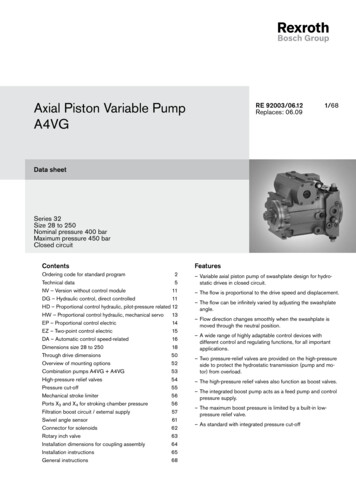
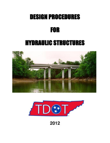
1/910/5/12DESIGN PROCEDURES FOR HYDRAULIC STRUCTURESTennessee Department of Transportation1. Determine the drainage area of the site, in mi2 (km2).2. Determine the hydraulic design responsibility. See below for details.3. Check for previous hydraulic studies at or near the site:A. Corps of Engineers, TVA and F.E.M.A. Flood Insurance Study and Maps. See TennesseeHydraulics Memorandum 04, “Index of Local Flood Studies by TVA, Corps of Engineersand F.E.M.A. Flood Insurance Studies”.B. USGS flood studies.C. Previous TDOT projects, bridge inspection reports, and TPR’s4.Check for stream gage data at or near the site. Gage should be within 50 % of the site'sdrainage area.5. All designs are to be in English units (except where metric is specifically called for).6. Determine the flood frequencies for the site, in ft3/s (m3/s). Discharges are to be determined asshown below. Methods are shown in order of decreasing preference. See TennesseeHydraulic Memorandum – 2 for additional information.Method 1: Existing FEMA Flood Insurance Study (FIS).Method 2: Analysis of gage data within the watershed.Method 3: Regression equations from the following USGS publications.For rural drainage basins: “Flood-Frequency Prediction Methods for UnregulatedStreams of Tennessee, 2000” WRIR 03-4176For urbanized drainage basins: “Synthesized Flood Frequency for Small UrbanStreams in Tennessee” WRIR 84-4182.7. Plot discharge vs. recurrence interval curve as shown in Figure 1.8. Determine the average flood energy grade slope for a reach upstream and downstream of thesite. This slope is usually approximately equal to the average streambed slope for that samereach. Using multiple methods such as USGS quadrangle maps, site survey, and floodinsurance studies to determine this slope is recommended.9. The skew of the culvert or the skew of the bridge substructures should be in alignment with thedirection of design flood flow downstream of the proposed structure. This will generally bewith the flood plain skew or the channel skew whichever is more site appropriate.10. Run a water surface profile model in HEC-RAS to determine the normal water surface profiles,the existing bridge water surface profiles and the proposed bridge water surface profiles alongwith any alternatives for the 2, 10, 50, 100, and 500 year events. If the bridge location is withina FEMA designated floodway and an existing HEC-2 model is available from FEMA, TVA, orthe Corps of Engineers, then import the HEC-2 model into HEC-RAS. Create a stage vs.discharge curve as shown in Figure 2. This curve should show all three water surface profilesand any alternatives at the upstream cross-section with highest proposed backwater.
2/910/5/1211. See Tennessee Hydraulics Memorandum - 01 “Box and Slab Culverts and Bridges” fordetermination of the type of structure required at the design site.12. For guidelines on selecting an acceptable structure size, refer to the following TennesseeHydraulics Memorandums:A. “Design of Waterway Openings” - 03B. “Improved Inlets and Energy Dissipaters for Culverts and Box or Slab Bridges” -06C. “Scour and Fill at Bridge Waterways” - 0813. Proper drainage of rainfall on the bridge deck shall be provided. See Tennessee HydraulicsMemorandum - 07 “Drainage of Bridge Decks”.14. Where Rip-Rap is required for slope protection, refer to Tennessee Hydraulics Memorandum 09 “Rip-Rap for Bridge Waterways, Open Channels and Grade Crossings”.15. The proposed bridge plans may be subject to approval by various other agencies. SeeTennessee Hydraulics Memorandum - 05 “Approval of Bridge Plans by Outside Agencies”.16. An on site visual inspection should be made of the existing hydraulic conditions. SeeTennessee Hydraulics Memorandum - 10 “On Site Inspection Report” for specific details of theinspection.17. Compile the hydraulic design file.18. The roadway designer should submit roadway plans to the Environmental Division in order todetermine permit requirements and for permit application. See Roadway Design Guidelinesand Tennessee Hydraulics Memorandum - 05 "Approval of Bridge Plans by Outside Agencies"for details.
3/910/5/12Figure 1: Example Flow versus Recurrence Interval
4/910/5/12Figure 2: Example Stage versus Discharge
5/910/5/12Hydraulic Design ResponsibilityThe Hydraulic Design and Permitting Section will be responsible for the hydraulic design of streamencroachments (bridges, culverts, channels, etc.) where the Q50 is greater than 500 ft3/s (14 m3/s)(by the USGS regression equations) at the downstream most portion of the encroachment.Additionally, replacement or rehabilitation of any existing structure 20 feet (6 m) long or longer orstructures on streams with a detailed FEMA Flood Insurance Study will be reviewed by theHydraulic Design Section and a determination of hydraulic design responsibility will be made.The roadway designer will submit to this office preliminary plans (typical sections, present andproposed layout, and profile, cross sections, etc.), location map, and survey information as indicatedin the Drainage Surveys Section of the Survey Manual for all stream encroachments (bridges,culverts, channels, etc.) whose Q50 is greater than 500 ft3/s (14 m3s) (by the USGS regressionequations) at the downstream most portion of the encroachment and for replacement orrehabilitation of any existing structure 20 feet (6 m) long or longer.The Design Division will be notified by the scheduled grade approval date or within 30 days ofreceipt of a complete grade approval request (whichever is longer) of the finished graderequirements for the stream encroachment.For the replacement or rehabilitation of any existing structure 20 feet (6 m) long or longer orstructures on streams with a detailed FEMA Flood Insurance Study, the Design Division will benotified whether the hydraulic design will be completed in this office or if they should proceed withreplacement under their hydraulic design criteria.Where removal of a portion of an existing structure is required for stage construction, the plansshould be forwarded to the appropriate Manager 2 in the Structural Design Section of the StructuresDivision for review and a request for stage construction details that will affect roadway designshould be made.The final hydraulic data and any additional drawings required to complete plans for the streamencroachment will be forwarded to the Design Division no later than the scheduled completehydraulics due date. At this time a Hydraulic Preliminary Layout should be forwarded to theDirector of Structures Division for structural design assignment.
6/910/5/12Design File RequirementsCompilation of a hydraulic design file will be required for hydraulic structures under theresponsibility of the Structures Division as discussed above.The hydraulic design file should be bound (8.5” x 11”) in the following approximate order and eachsection tabbed separately.1.2.3.4.5.Correspondence in chronological orderMaps- located on a portion of the county map or city map and 7.5 minute USGS quadrangle(preferably color).Hydraulic report summary form as shown below.Photographs - See THM-10 for minimum requirements. Aerial photographs should beincluded if available.Analysisa)Discharge calculations.b)Frequency discharge relationship as shown in Figure 1 above.c)Stage discharge relationship as shown in Figure 2 above.d)Supporting hydraulic information (previous flood studies, gage data, etc.).e)Existing structure analysis, with cross sections plotted (if applicable).f)Natural water surface model with no bridge or road fillg)Proposed structure analysis, with cross sections plotted and any alternatives.h)Scour analysis, if applicable.i)Deck drainage analysis.j)On site inspection report.k)Other information.Where multiple structures occur on a single project, the correspondence section should not berepeated. The cover of the design file should include the project description, PIN, and / or projectnumber as indicated in Department schedules. Also each stream crossings station, stream name andassociated bridge identification number (if available) should be indicated on the cover. Survey datashould be included in the file for future reference.The hydraulic design file will be filed in the Hydraulic Design Section’s files.
7/910/5/12STATE OF TENNESSEEDEPARTMENT OF TRANSPORTATION - DIVISION OF STRUCTURESHYDRAULIC REPORTDate:Designer:A.SITE DATA1. LOCATIONa. Name of Stream:b. Route Name:c. Route No.:d. County:e. City:2. VICINITYa. See attached location map or bridge survey.b. Nature of Stream Bed:c. Bank subject to Erosion:d. Should Drift be a consideration:3. EXISTING BRIDGE DATAa. Bridge Location No.:b. Bridge Selection No.:b. Drawing No.:c. Bridge Length:d. Bridge Width:e. Bridge Type:f. Bridge Skew:g. Drainage Area:h. Design Discharge:i. Design Frequency:j. Design Water Area:k. Design Elevation:l. Design Backwater:m. Design Velocity:n. Overtopping El.:ft.ft. mi2.ft3/sYearft.2ft.ft.ft/sft.Channel Mile:P.E. No.:Project No.:USGS Quad #:Name:Severe 10 Stable 0Extreme 10 No 0ft.ft. mi2.ft3/sYearft.2ft.ft.ft/sft.4. EXISTING WATER STAGES AT PROPOSED BRIDGE SITEa. Maximum High Water El.:Date://Frequency:yearSource:b.Year High Water Elevation:ft.c. Datum Elevation:ft.Ordinary High Water Elevation:ft.d. In Reservoir (Y/N):Reservoir Name:Normal Pool Elevation:ft.Minimum Pool Elevation:ft.e. Backwater Elevation:ft.From:
8/910/5/12B. HYDROLOGICAL ANALYSIS1.FLOOD RECORDSa. Floods in Tennessee - Magnitude and Frequency - 2003 [ ] U.S.G.S. [ ]Corps of Engineers [ ] TVA [ ] Other [ ]b. Stream Gage No.:At Site [ ] In Vicinity [ ]c. None Available [ ]2.a.DRAINAGE AREAsq. mi.3.DISCHARGEMagnitude:Frequency:2 yr5 yr10 yr25 yr50 yr100 yrProposed Overtopping:Frequencyyear & DischargecfsSource:Floods in Tennessee - Magnitude and Frequency – 2003Corps of EngineersTVAFederal Insurance StudyCounty or CityOtherSTREAM SLOPEFrom U.S.G.S. Quad Map:ft./ft.From Site Survey Data:ft./ft.From Flood Flow Profiles:a.b.c.4.a.b.c.Calculated:Published:500 yrC. HYDRAULIC ANALYSIS OF PROPOSED BRIDGE1.a.PROPOSED STRUCTUREStation:Design Frequency:Design Velocity:Design Bridge Backwater El:Design Waterway Area:b.Is Bridge Backwater a consideration? (Y/N) :Year Bridge Backwater:ft.Year Bridge Backwater Elevation:ft.Describe Control:c.Are Spur Dikes Needed (Y/N) :Describe Reason:d.Is Channel Transitioning Involved (Y/N) :See attached detail.e.Is Channel Change Involved(Y/N) :See attached detail.f.g.Is Bank Protection NeededFinal Layout: See Drawing No.(Y/N) :See attached detail.Drainage Area:yearDesign Discharge:ft/sDesign Bridge Backwater:ft.Roadway Overtopping Elevation:ft.2 below elev.ft.mi.2.ft3/sft.ft.
9/95/5/97D. SCOUR ANALYSIS OF PROPOSED BRIDGE1.CHANNEL CHARACTERISTICSa.USGS/TDOT "observed" scour ranking at existing bridge is, or at nearest bridge upstream []/downstream [ ] is(Br. No.).USGS/TDOT "potential" scour ranking at existing bridge is, or at nearest bridgeupstream []/downstream [ ] is(Br. No.).Current stage of channel evolution : Stable [ ] Degrading [ ] Widening [ ] Aggrading [ ]Streambed material type: silt/sand [ ]; coarse gravely sand [ ]; gravel/cobbles [ ];gravel and cobbles on rock [ ]; slab rock [ ]b.c.d.2.COMPUTED SCOUR DEPTHa. Design discharge (yr.) cfsb. Design velocity (yr.) fpsc. Estimated degradation [ ] /aggradation [ ] ft.d. Estimated contraction scour ft.e. Estimated pier scour ft.f. Estimated total scour depth ft.g. Preliminary ftg. and/or pile tip elev. (based on soils report? Y/N):h. Comments :E.OTHER AGENCY REVIEW and/or APPROVALYESNOCorps of Engineers – IndividualCorps of Engineers - NationwideTennessee Valley AuthorityU. S. Coast GuardTennessee Wildlife Resource AgencyState Water Quality ControlFederal Highway AdministrationFederal Emergency Management AgencyLocal Government, if participating in FEMA ProgramIndividual ARAP requiredGeneral ARAP requiredNational Pollutant Discharge Elimination System (NPDES)Is the location governed by the National Flood Insurance Program Regulations? (Y/N):Has the TDOT policy on selection of Design Flood Frequency been satisfied? (Y/N):F.REMARKS
THM-01 1/411/16/12TENNESSEE HYDRAULICS MEMORANDUM - 01Box and Slab Culverts and BridgesDistribution: Office, ConsultantsDefinitions for Cast-In-Place & Precast Concrete and Corrugated Metal StructuresBox Culvert - A box type structure consisting of a single box or multiple boxes with a bottom slab, having a lengthmeasured along the centerline of the roadway of less than 20 feet (6.1 m) between the extreme ends of the openings.Slab Culvert - A structure consisting of a single box or multiple boxes without a bottom slab, having a length measuredalong the centerline of the roadway of less than 20 feet (6.1 m) between the extreme ends of the openings.Box Bridge - A box culvert type structure consisting of a single box or multiple boxes with a bottom slab, having alength measured along the centerline of the roadway of more than 20 feet (6.1 m) between the extreme ends of theopenings.Slab Bridge - A structure consisting of a single box or multiple boxes without a bottom slab, having a length measuredalong the centerline of the roadway of more than 20 feet (6.1 m) between the extreme ends of the openings.Girder Bridge - A structure erected over a stream, watercourse, highway, railroad or opening, for carrying traffic,having a length measured along the centerline of the roadway of more than 20 feet (6.1 m) between the faces of the endsupports and consisting of a distinct superstructure and substructure.Precast Concrete Arch – A precast arch structure of varying shape consisting of one or more barrels that can beconstructed on precast or cast in place strip footings, pile supported strip footings or a concrete bottom as required bysite conditions.Corrugated Metal Arch - A steel or aluminum arch structure of varying shape consisting of one or more barrels that canbe constructed on precast or cast in place strip footings, pile supported strip footings or a concrete bottom as requiredby site conditions.The distinction between Culverts, Box Bridges and Girder Bridges is important in that separate bid items for concreteand reinforcing are provided for each. See SMO13-04 and Tennessee Standard Specifications Articles 101.07, 101.08and 604.32. Pre-cast concrete or metal structures are often bid lump sum.The distinction between slabs and boxes is important in that it establishes whether or not the structure has a bottomslab. When the foundation for the structure is capable of providing sufficient bearing resistance and is a non-erodiblematerial such as suitable bedrock then the bottom slab is replaced by a small footing to support the walls of thestructure forming a three sided structure. When the foundation material is erodible, the bottom slab serves as thestructure foundation and is a complete four sided structure.In cases where a box is specified and suitable rock is within three feet of the streambed, the field engineer maysubstitute a slab structure and vice versa when rock is not available as anticipated. Leveling concrete may be used foruneven bedrock in some situations.Precast concrete arch or metal arch structures should be considered for use when environmental impacts dictatespanning a stream that is not necessarily large enough to warrant a girder bridge but prohibits the use of a box or slabbridge, aesthetic issues such as high visibility to a neighborhood, public park, or historic area, and/or time ofconstruction is an issue and can be improved over a cast in place structure.
THM-01 2/411/16/12Available StandardsBox and Slab Culverts and Bridges are primarily used to provide roadway crossings for small streams. They are alsoused as cattle and machinery passes. Openings are sized to suit their intended use. Stream crossings are sized based onthe hydraulic design as described in THM-03. A large selection of standard box and slab culverts, improved inlets, andenergy dissipaters has been developed and are on file in the Division of Structures. An index of all available box andslab standard drawings is maintained by the Division of Structures on the TDOT website.Standards are available for a wide variety of barrel heights and widths, number of barrels, skews and fill heights.Barrel widths of 6 feet to 18 feet increasing in 2 feet intervals are available in single, double and triple barrels. Thebarrel heights vary from 4 feet up to a height equal to a single barrel width increasing in increments of 1 foot. Thesecombinations provide a size range from a single 6' x 4' to a three at 18' x 18' with corresponding single openingsranging from 24 square feet to 324 square feet respectively. More than three barrels at any one crossing should beavoided for debris accumulation and cost issues unless site conditions specifically call for more than three barrels. Thehydraulic characteristics for a culvert may be improved with special inlet details. See THM-06 for details on improvedculvert inlets.Culvert end skews are available for 45 , 60 , 75 and 90 . Although the field engineer will construct the box to theexact skew (the angle between the centerline of the culvert and the centerline of the road) of the crossings the designand details of the closest available culvert end skew may be used for estimations.Standard details also vary depending on the amount of fill to be placed on the box. Fill height shown on the standarddrawings is measured from the bottom of the top slab to the top of the fill. When the fill height is less than one foot the"No Fill" section shown on the standard drawings may be used. Details are available for fill heights of 3 feet, 5 feet,and 10 feet to 60 feet (increasing in increments of 10 feet).Use of old standards for extensions of box or slab culverts or bridges that are no longer standard sizes such as 15’x15’or where the height is larger than the span, should be avoided where possible and limited in all cases to fill heights lessthan 10 feet. Current standards may be used with 1:1 transitions to the height and span.The proper way to designate a box is to list, in order, the number of barrels, barrel width, height, skew and fill height.For instance, a 3 @ 10' x 8' @ 45 and 30 feet of fill would be three barrels each 10 feet wide and 8 feet high skewed45 and designed for a 30 feet high fill.Other standards will be developed as necessary to provide skews, openings or fill heights not available on the currentlist of standards.Quantities and Cost EstimatesThe quantities shown on the standards are given per foot of box length for each combination of culvert height and fillsection. Quantities for wings, cut-off walls, debris deflection walls, and edge beams are shown on separate drawings.See Structures Memorandum 013 for instructions regarding cost estimates for boxes and slabs.Contract Drawings and SpecificationsRoadway plans in the contract drawings show the location, skew, elevation, size, fill height and Standard Drawingsapplicable for the construction of each box or slab. The location is shown on the roadway plan and profile. The length,elevations and fill height are shown in a roadway cross section. The project engineer has some flexibility in adjustingthe location to fit field conditions unless otherwise noted on the plans.All hydraulic data for Bridges and Culverts shall be shown on the roadway plan profile sheet as follows:
THM-01 3/411/16/12Station 50 12.50, 3 @ 12' (m) x 4' (m) 75 skew box, skewed 80 to centerline survey.Drainage Area 5.2 mi2 (km2)Design Discharge (100 year) 387 cfs (m3/s)100 yr. Bridge Backwater 0.76 ft (m) at El. 122.63100 yr. Velocity 3.0 fps (m/s)500 yr. Discharge 562 cfs (m3/s) at El. 122.87Inlet Invert El. 119.20Outlet Invert El. 118.90Roadway Overtopping El. 124.20Std. Dwg. No. STD-17-?Excavation and backfill for boxes and slabs shall be in accordance with the Standard Specifications and currentStandard Drawing.Bridge Deck FormsPrecast, prestressed concrete panels are frequently being used by contractors to form the top slabs or decks of manystructures. When reviewing shop drawings for precast deck panels, the reviewer should be very familiar with BridgeDeck Panel Standard Drawings and current Structural Memoranda. The check list on SM054-08 will be of specialbenefit to the reviewer.Deck panels for design spans greater than 20 feet (6.1 m) should be reviewed as precast prestressed box beams.Elastomeric bearing pads may be required as indicated by the design chart for deck panel bearing material found in thecurrent standard drawings.Bridge Deck ReinforcingBox and slab structures are in many cases designed requiring only minimum fill (0 to 10 ft (m)) over the top slab. Inorder to protect the reinforcing and extend the life of the box, epoxy coating is to be specified for the top mat steel ofthe top slab. The bridge designer will specify which projects to call for epoxy coated steel and notify the roadwaydesigner accordingly.The following notes will be included on all metric standard culvert drawings. If these notes are not on the culvertdrawings being used, then they should be added to the roadway plans.Epoxy coated steel shall be provided for all reinforcing bars in the top mat of the top slab and curbs,including tie bars for curbs and corner bars for exterior walls. All other steel is to be black bars.Additionally, a footnote is to be shown on the box or slab bridge quantity tabulations for the reinforcing steel bid item:The unit cost for bid item 604-02.02 is to include any additional cost for epoxy coated steel as notedon the plans details.Standard Slab BridgesReinforced slab bridges can provide economical and attractive solutions to short span bridge needs. In recent yearsslab bridge designs have been overlooked due to the desire to reduce the quantities of concrete and steel required. Inthe past decade, with the rise of labor rates, slab bridges have become economical due to the simplicity of design andease of construction.
THM-01 4/411/16/12There is also an environmental benefit to having a natural bottom in the culvert as three sided structures have gainedfavor with the permitting agencies.Slab bridges also allow much shallower superstructure depths requiring less approach fill. Slab bridges areeconomically competitive for spans up to 54 feet (16 m).
THM-02 1/211/16/12TENNESSEE HYDRAULICS MEMORANDUM - 02HydrologyDistribution: Office, ConsultantsGeneralBefore hydraulic design can begin the designer must have a thorough understanding of the hydrology of the projectsite. A hydrologic study must be undertaken to determine flood flows at a particular project location. If significantwatershed urbanization is expected within the next 20 years, then future conditions should be taken into account whenanalyzing hydrology and proposed flows should reflect the expected watershed changes.Sources of Hydrologic InformationThe following methods of determining hydrology are acceptable, in order of decreasing preference. Properdocumentation of the method used should be provided in all cases, as well as a graph of the resulting flow versusrecurrence interval.Method 1: Existing FEMA Flood Insurance Study. If the project site is located within a city or countywhich participates in the National Flood Insurance Program (NFIP), then flood flows have likely beenpreviously calculated by a detailed engineering study. The appropriate Flood Insurance Study (FIS)should be consulted. In order to provide continuity with the NFIP, flows obtained from a FIS are highlypreferable.Method 2: Data available from stream gages located in the watershed. The U.S. Geological Survey(USGS) and U.S. Army Corps of Engineers (Corps) own and operate numerous stream gage stationsthroughout the state. If one of these is present within 50% of the drainage area, the appropriate agencyshould be consulted to obtain flow versus recurrence interval data. If the gage is located at the projectsite, then this data may be used for project hydrology. If gage data is not available on site, data fromnearby gages should be used to evaluate results from Methods 1 and 3.Method 3: Regression. The USGS has performed studies to determine the flow characteristics of ungagedwatersheds. Rural basins should use the methods discussed in “Flood-Frequency Prediction Methods forUnregulated Streams of Tennessee” WRIR 03-4176. Flood flows for urban basins should be calculatedusing the methods discussed in "Synthesized Flood Frequency for Small Urban Streams in Tennessee”WRIR 84-4182. Further discussion of the rural methods is included below.All methods should not be blindly accepted and should be evaluated for validity prior to using and all verificationefforts should be documented in the design file. The Hydraulic Design Section reserves the right to require a moredetailed study at high risk project locations, or when deemed necessary due to unusual circumstances such as karsttopography or storage within the watershed.Rural Regression MethodsAs mentioned previously, flood flows for rural ungaged basins may be obtained using methods discussed in WRIR 034176. This publication provides three methods for determining flood flows, the single regression equations (SRE), themultiple regression equations (MRE), and the region of influence method (ROI). The SRE and MRE methods may bedone manually, however the ROI method may only be done using a computer program provided by the authors ofWRIR 03-4176. The publication and supporting computer application may be obtained from the he program provided with WRIR 03-4276 computes flows for a given site using the SRE, MRE, and ROI methods.The three methods should be compared and the method with the lowest calculated error should be used to determine
THM-02 2/211/16/12flood flows for the structure. In certain cases, the program calculates outlier flows which it then corrects using a linearinterpolation method (see WRIR 03-4276 for further detail). We do not recommend using this method for design. Incertain high risk situations where conservative design is warranted the method resulting in the highest flows may beused rather than the method resulting in the lowest errors.The USGS Streamstats web based program provides the drainage area, hydrologic area, watershed slope and flows forthe MRE method. The SRE method flows are given where gaps in the MRE exist. This application may be used formost locations in Tennessee if the site is large enough to be included in the state GIS hydrology dataset. Exceptions arein the Mississippi River flood plain and in karst areas where the information should be checked by other sources.
THM-03 1/510/5/12TENNESSEE HYDRAULICS MEMORANDUM - 03Design of Waterway OpeningsDistribution: Office, ConsultantsGeneralBridges and culverts should provide waterway openings which will not produce excessive backwater or scouringvelocities. The minimum structure length should be that which will bridge the natural or man-made stream channel.The structure should be designed so that the accumulation of debris on the structure is minimized.Design Frequency CriteriaThe minimum "design flood" magnitude for stream crossings on State Routes is the 10 year frequency runoff and forInterstates and other 4 or more lane routes it is the 100 year frequency runoff. An analysis using the design condition ismade of the flood risk to the highway, and the effect of the proposed crossing on the possible damages to surroundingproperty, the stream stability and the environment. Drainage facilities for Off-System and/or low traffic volumesystems may be based on lesser floods if the conditions of the site warrant lower standards. The selection of the"design flood" includes consideration of construction cost analysis, probable property damage, the cost of trafficdelays, the availability of alternate routes, emergency supply and evacuation routes, the potential loss of life andbudgetary constraints.The interstates were originally designed for a 50 year flood frequency. That should now be upgraded to the 100 yearfrequency as with other 4 or more lane routes when economically feasible and constructible. The Design Divisionshould be consulted to help determine this feasibility and applicability to the project.When hydraulic structures are required on existing routes, the existing roadway grade may not be suited to being raisedto desired design frequency. In this case a design exception would be required. See ADDENDUM of THM-03.The hydraulic design for bridge crossings and/or encroachments shall be consistent with standards established by theFederal Emergency Management Agency and local governments for the administration of the National Flood InsuranceProgram.Peak discharges should be reduced when floodwater retarding structures and/or reservoir systems are "existing"upstream from the bridge crossing, or can be expected to be in service upon completion of the highway construction.The appropriate Flood Control Agency should be contacted for computation of the reduced discharge.Bridge OpeningsWaterway openings should be designed to keep scour in the main channel and the overbanks within reasonable limitsfor which the bridge may be designed to withstand. It should be able to pass the 500 year flood without causingstructural failure.
Director of Structures Division for structural design assignment. 6/9 10/5/12 Design File Requirements Compilation of a hydraulic design file will be required for hydraulic structures under the resp