Transcription
Basics of Room Air DistributionDan Int-HoutChief Engineer / KruegerRichardson Texas3/22/2011
Study Objectives 2Main issues of thermal comfortPrinciples of air distribution as they relate tohuman comfortPrinciples of space air distributionFunctions of the different types of airdistribution devices
Where We Are Today:
Occupant Comfort
Thermal Interchange Between Peopleand Environment5
Temperature and Humidity ComfortZone 6Dry-bulb temperature, FRelative humidity, rhThermal radiationAir movement, fpmInsulation value of clothing, cloActivity level, metDirect contact with surfaces not at bodytemperature
ASHRAE Standard 55-2004ThermalEnvironmental Conditions forHuman Occupancy7
For 80% Thermal Acceptance 8Activity levels are between 1 and 1.3 met.Clothing is near 0.5 or 1 clo.Average Air speeds are below 40 fpm.
9
Avoid in humid climateto avoid mold10
Ideal target conditions11
Low humidity ahealth issue12
Graphical Solution Program
Thermal ComfortASHRAE Standard 55-2010 mandates a maximum 5.4 F vertical temperaturestratification in Occupied ZoneVelocities within the occupiedzone shall be 50 FPM2’Floor to Occupants’ Head Level(3.5 ft. for seated, 6 ft. for standing occupants)2’
Comfort Economics ASHRAE Journal, June 2008
LEED ‘09 ASHRAE Std 55 Checklist
Indoor Air Quality
Indoor Air Quality Standing Standard ProjectCommittee 62.1 Residential Committee is62.2 Current Standard is62.1-’13 Several addenda for the’13 version have alreadybeen approved, and will bepublished in a compiledaddenda, every 18 months(or so).
“air in which there are no knowncontaminants at harmfulconcentrations as determinedby cognizant authorities andwith which a substantialmajority (80% or more) of thepeople exposed do not expressdissatisfaction”19
Two Compliance Paths: Ventilation rate procedure–––– 20Prescribed rates in Table 6-1 : cfm/person pluscfm/square footOffice: 5 cfm/person plus 0.06 cfm/ft2Default 17 cfm / person in an officeOnly 5.5 cfm/person in Hotel multi purpose spaceIndoor air quality (IAQ) procedure
IAQ Standard Standard 62 is on continuous maintenance. Continuous and incremental changes are inprogress. It will attempt to be in coordination withbuilding codes. A Guideline document for designing systemsabove minimum requirements is being created. Users Manual is available now. The IMC has referenced 62.1 in the 09 releaseof the mechanical code. There seems to be minimal public awarenessof the dynamic nature of the Standard.
Acoustics
Acoustics: AHRI 885-08 acoustical application standard.AHRI 880-08 air terminal test standard.AHRI 260-01 ducted equipment except air terminals.ASHRAE 70, air diffuser performance.Acoustical quality suggests the use of RC (or newermeasures) rather than NC. Many acousticians areheading back to dBA! LEED V4 includes acoustical credits and requirements,and references AHRI 885. A new ruling by AHRI will change everyone’sdischarge sound ratings considerably.
End Reflection Low frequency sound traveling down a duct willpartially reflect back when encountering a rapidchange in area. The smaller the duct, the greater the effect. It can be as much as 10dB at 125Hz. It is muchless at higher frequencies. Since NC is usually set at 125Hz, reported NCcan go up as much as 10NC. Most importantly, Specifying Engineers shouldbe modifying their discharge soundrequirements to reflect the new data.
End Reflection
Sound Specifications Should be based on clearly stated assumptions. Should reflect real project needs, not anymanufacturer’s data and use currently acceptedapplication factors. If duct lining is used – require: ”NC shall be determinedin accordance with AHRI 885-08, Appendix E”,otherwise specify octave band sound power. Specifications need to be modified to account for thenew reported data. Over-silencing increases both initial costs andoperating costs, and may hinder proper IAQperformance.
Air Distribution Principles
Outlet Types Grille: movable or fixed blades to direct theair and adjust width of jet.– 28Works well in floor, sill and wall.Slot diffuser: long, narrow slot producingrapid diffusion; use a grille for the ceiling.Ceiling diffuser: rings of pressed metal tosupply air across the ceiling.
Outlet Accessories Dampers: opposed blades adjust flow whileparallel blades also adjust direction.– 29Be careful of significant flow adjustment atdamper due to noise. Quieter, less noticeable airnoise, when flow is adjusted at branch.Directional vanes to collect or direct airflow.
Outlet Selection 30Understand the space, esthetics, and airsupply access.Determine quantity of air to be supplied.Select type: air quantity, throw, obstructionsin the space, and architecture.Locate outlets for uniform distribution.Select proper size.
Return or Exhaust Inlets 31Any style of outlet. Free area for air transferis required.No effect on general flow around the space.Position so primary air is not collected.Good in stagnant zone.
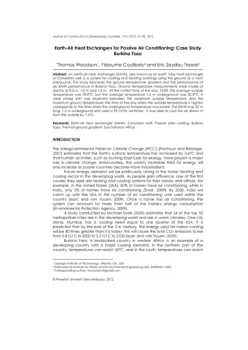
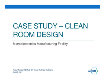
Understanding The TerminologyPrimary Air Jets - Air jets from free round openings,grilles, perforated panels, ceiling diffusers and otheroutlets can be defined by three variables. Throw Drop Spread
Understanding The TerminologyTHROWDROP
Understanding The TerminologySpread - is defined as the divergence of the airstream in a horizontal or verticalplane after it leaves the outlet.50 fpm22.5Typical 100 fpm22.5150 fpm
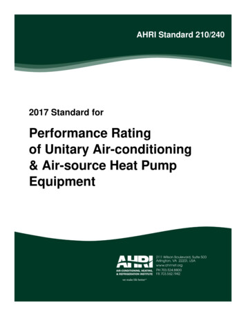
Understanding The TerminologyCoanda Effect - a negative or low pressure area is created between themoving air mass and the ceiling at or near the supply air outlet. This lowpressure area causes the moving air mass to cling to and flow close to theceiling surface and increases the throw.Coanda Effect
Understanding The TerminologyUnderstanding primary air jet variables enables Accurate prediction of room air flow Improvement of thermal comfort Proper selection of grilles, registers and diffusers Adherence with ASHRAE Ventilation Std 62.1 as aLeed PREREQUISITE, and in the 2009 IMC
Understanding The TerminologyThe Basis of Catalog Performance Data Throw – The horizontal or vertical axial distance anairstream travels after leaving an air outlet, usuallyassumes a surface adjacent to the air outlet Pressure – Can be total pressure or static pressure Sound – Can be either NC or Octave Band data
Throw Throws are cataloged for 150, 100 and 50 fpmterminal velocities. Throws should be selected so that jets do notcollide, but have sufficient projection for the area tobe served.150fpm100fpm50fpm7 – 8 – 12
PressurePSPTPressure – Air outlet pressure data isrequired to properly size the air deliverysystem within a building. Static Pressure – The outward force of airwithin a duct, measured in inches of watercolumn. Velocity Pressure – The forward movingforce of air within a duct, measured ininches of water column.PS Total Pressure – The sum of the velocityand static pressures, expressed in inchesof water column and can be obtained byuse of a pitot tube.PT PV PSPT
SoundSound levels reported for diffusers are conducted inaccordance with ASHRAE Standard 70. Catalog sound data assumes 10 diameters ofstraight duct. Room absorption is assumed to be 10dB in allbands. In practice however, room sound levels areprobably 5 NC higher than reported.
Air Distribution, Poor Pattern
Air Distribution, Good Pattern
Understanding ADPI
ADPI ADPI is the percentage of points within the occupied zonehaving a range of effective draft temperatures of -3 to 2 ofaverage room temperature at a coincident air velocity lessthan 70 FPM. ADPI is essentially a measure of the degree of mixing inzones served by overhead cooling systems. When air distribution is designed with a minimum ADPI of80% the probability of vertical temperature stratification orhorizontal temperature non-uniformity is low andconformance with ASHRAE Standard 55 (Thermal Comfort)requirements is high. ADPI does not apply to heating situations or ventilationrelated mixing.
ASHRAE Fundamentals Chapter 20, Table 3 ADPI selection using T50 / Lwas developed in the ‘60swhere L is the distance to thenearest wall or halfway to thenearest air outlet. A relationship was foundbetween 50 FPM/minisothermal throw and coolingthrow, Using this table engineers canassure clients that diffuserselections will provideacceptable mixing and airchange effectiveness.
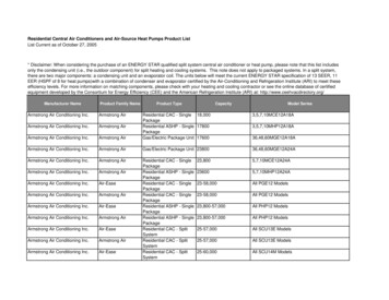
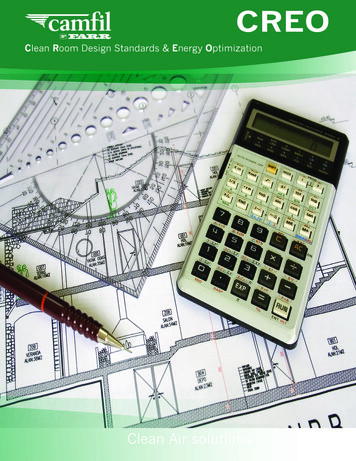
Perforated 24X24, 10” inlet, 4 way, 20 Delta-TSpacing for 80% ADPI1614CFM1/2 Unit Separation DistanceNC M/Sq.Ft.3.03.54.04.55.0
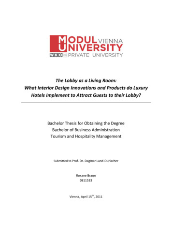
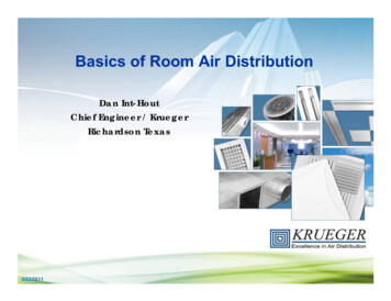
Prism 24x24Prism, 24”x24”, 10” inlet, 20 ΔTSpacing for 80% ADPI10in. Neck24NC 371 /2 U n it S e p a ra tio n D is ta n c e , fm/SqFt1.61.82.02.22.42.6
Room Air SpeedIssues and Factors Standard 55 says thermal comfort can be achievedwith 0 fpm air motion. Uniform air temperatures indicate good mixing whenloads are present. With conventional (well-mixed) systems, room airspeed is driven primarily by room loads when airsupply is below 0.9 CFM/sq. ft. and air diffusion isadequate per ASHRAE sponsored research Partitions can provide excellent comfort with ceilingdiffusers when cooling.
ASHRAE Journal, 2004, on overheadair distribution selection
Common Overhead Heating DesignColdOutsideWindowTHERMOSTAT
Overhead Heating PerimeterConsiderations: Maximum delta-t for effective mixing when heatingfrom overhead, per ASHRAE handbook ?. 15 F (90 F discharge), continuous operation. 150 FPM should reach 4-5 feet from the floor. ASHRAE 62.1 requires that ventilation be increasedby 25% when heating, if the above rules are notfollowed. Throw toward and away from glass. Typical perimeters require only 8 F Delta-t@ 1cfm/sq.Ft.
Proper Perimeter Design
Perimeter Considerations:See March 2007 ASHRAE Journal:
LEED & ASHRAE CodeCompliance In LEED 2009 and later, in order to get ANY LEED points, onemust fully meet the Ventilation Rate Procedure calculation inASHRAE Standards 62.1 (Ventilation)ASHRAE 62.1-2013 VRP requires that if heating air suppliedfrom the ceiling is less than 15 above room temperature butdoes not reach within 4.5 feet of the floor at 150FPM theoutdoor air supply must be increased by 25%.ASHRAE 62.1-2013 VRP requires that if the heating air suppliedfrom the ceiling is greater than 15 above room temperature theoutdoor air supply must also be increased by 25%.LEED V4 Ventilation points are again gained by increasedventilation 30% beyond 62.1 minimums.
Non-Inductive Air DistributionLaminar and Radial Flow OutletsLaminar FlowRadial Flow Hospital Operating Suites Hi-Tech Electronics and other industrialapplications Clean Rooms Laboratories
UFAD: Underfloor Air Distribution A raised floor allowselectrical andcommunicationcircuits to be easilyaccessed andchanged.Air may be distributedwithin this space,without ductwork.Ducted perimeter with fan poweredboxes, or other techniques, depending onclimate, glass load, etc.Pressurized plenum for core
Interior Outlet Selection –1/workstation
Perimeter outlet selection Perimeter solutions vary considerablyAvoid condensing coils under the floorHydronic coils often leakExhaust at the perimeter to draw heataway Best solutions seem to be heat and coolfrom overhead
Displacement Systems 59To be added
Select based on ”adjacent zone”
AtriumsGymsAnd more
Non Typical Throw Analysis
Special ApplicationsHigh bay application - Ceilings over 12’ high Heating is a challenge due to buoyancy.– Take advantage of vertical stratification where possible– Required Heating airflow rate may exceed cooling airflowrate.– Keep heating supply air temperature to roomtemperature ΔT to a minimum If supplying air distribution from the ceiling, consider usinground diffusers, drum louvers, or diffusers with somevertical projection. One cannot use ADPI to predict heating performance. Consider Displacement Ventilation for cooling applications
Diffuser Selection & Buoyancy ADPI isn’t always the best way to analyze, select andplace diffusers, especially with heating and high bayapplications. One can estimate Throw as a function of ΔT andbuoyancy. Simple rule: Distance to 75ft/min is affected by1%/degree(F) ΔT.Example:1. 20 ΔT Cooling, Vertical Down 20% projection2. 20 ΔT Heating, Vertical Down -20% projection3. 20 ΔT Heating, Along Ceiling 20% projection
Side Wall Register Selection &Buoyancy Horizontal free jet: Vertical change @ 75ft/min is affected by1% of 75fpm throw/F0 ΔT.Example: 15oF Delta T heating15% T75T75Note: T150 is not affected by Delta-t
Entrained vs. Free Jets Most catalog throw data assumes jet is along a surface. Exceptions include drum louvers, duct mounted grillesand vertical linear diffusers. A free jet will be shorter than an entrained jet because ithas more surface area to induce surrounding air, whichshortens throw.
Special ApplicationsContinuous Duct Application Suggestions: Use multiple drum louvers, duct mounted grilles andcontinuous linear applications (longer than 10’). Size duct as large a possible (Duct inlet velocity 1000fpm). If inlet velocities are less than 1000fpm, maintainconstant duct size through entire length of run andbalancing will be minimal.
Returns Typically, returns are located in the ceilingin offices. Returns have an almost immeasurableeffect on room air flows below 1.5 cfm/sf. Suspended ceilings typically leak 1cfm/sfat 0.1” differential pressure. Spaces with high airflow rates can benefitfrom low returns.
Air Distribution Summary LEED 2009 requires meeting Standard 62.1 for projectapproval-No compliance No Leed project designation! Documented use of ADPI is the ONLY way to ass
22.03.2011 · ASHRAE Standard 55-2010 mandates a maximum 5.4 . ASHRAE 62.1-2013 VRP requires that if heating air supplied from the ceiling is less than 15 above room temperature but does not reach within 4.5 feet of the floor at 150FPM the outdoor air supply must be increased by 25%. ASHRAE 62.1-2013 VRP requires that if the heating air supplied from the ceiling is greater than 15 above .