Transcription
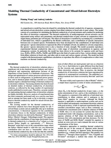
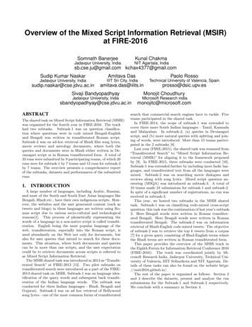
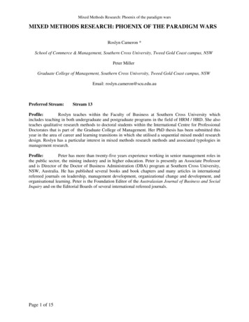
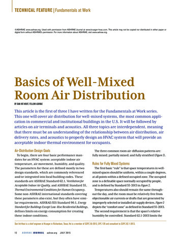
TECHNICAL FEATURE Fundamentals at Work ASHRAE www.ashrae.org. Used with permission from ASHRAE Journal at www.krueger-hvac.com. This article may not be copied nor distributed in either paper ordigital form without ASHRAE’s permission. For more information about ASHRAE, visit www.ashrae.org.Basics of Well-MixedRoom Air DistributionBY DAN INT-HOUT, FELLOW ASHRAEThis article is the first of three I have written for the Fundamentals at Work series.This one will cover air distribution for well-mixed systems, the most common application in commercial and institutional buildings in the U.S. It will be followed byarticles on air terminals and acoustics. All three topics are interdependent, meaningthat there must be an understanding of the relationship between air distribution, airdelivery rates, and acoustics to properly design an HVAC system that will provide anacceptable indoor thermal environment for occupants.Air-Distribution Design GoalsTo begin, there are four basic performance mandates for an HVAC system: acceptable indoor airtemperature, air movement, humidity, and quality.The parameters for these are defined mostly in twodesign standards, which are commonly referencedand/or integrated into local building codes. Thesestandards are ASHRAE Standard 62.1, Ventilation forAcceptable Indoor Air Quality, and ASHRAE Standard 55,Thermal Environmental Conditions for Human Occupancy.Some non-ASHRAE international standards coveringthese parameters also exist, but they often have similar requirements. ASHRAE/IES Standard 90.1, EnergyStandard for Buildings Except Low-Rise Residential Buildings,defines limits on energy consumption for creatingthese indoor conditions.The three common room air-diffusion patterns are:fully mixed; partially mixed; and fully stratified (Figure 1).Rules for Fully Mixed SystemsThe first basic “rule” is that space temperatures in wellmixed spaces should be uniform, within a couple degrees,at all points within a defined occupied zone. The occupiedzone is a definable space normally occupied by people,and is defined by Standard 55-2013 in Figure 2.Temperatures also should remain the same throughout the day, and the room must be relatively free fromobjectionable air currents or drafts that are generated byimproperly selected or installed air supply devices. Figure 2depicts the “comfort zone” as defined in Standard 55-2013.The second requirement is that the space’s relativehumidity be controlled. Standard 62.1-2013 limits theDan Int-Hout is a chief engineer at Krueger in Richardson, Texas. He is a member of SSPC 55-2013, SPC 129 and consultant to SSPC 62.1-2013.12ASHRAE JOURNALashrae.orgJ U LY 2 0 1 5
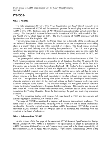
TECHNICAL FEATUREJ U LY 2 0 1 5ElevationElevationElevationElevationrelative humidity to 65% maximum.FIGURE 1 Characteristics of air-distribution patterns (2011 ASHRAE Handbook—Fundamentals).This means that when in coolingand dehumidification mode with anStratifiedFullyall-air HVAC system, the supply airStratifiedStratifiedFully Mixedmust have a dew-point temperatureMixedlow enough to keep the indoor airMixedborne moisture controlled. Typically,Local TemperatureLocal TemperatureLocal TemperatureLocal Temperaturethe dew point of the supplied air isCO2 ConcentrationCO2 ConcentrationCO2 ConcentrationCO2 Concentrationno greater than 55 F (13 C) for conPartially Stratified Room Air-Distribution Systemsventional all-air systems.Finally, a minimum quantity ofFully Stratified Room Air-Distribution SystemsFully Mixed Room Air-Distribution Systems“ventilation” air needs to be introExamples:Examples:Examples:duced into the space. This typically Thermal Displacement Underfloor Air Distribution (Using Room Air Induction) Overhead Mixed Air Supply inUsing Low Velocity Cool Air Operating in Cooling ModeCooling Operationrefers to outdoor air, but it may con NaturalVentilation UnderseatAirDistribution(UsingRoomAirInduction) Fan Cell Units and Unit Ventilatorstain some cleaned, recycled air if theOperating in Cooling Mode High Velocity Floor Based Supplyrequirements of ASHRAE Standard Task/Ambient Cooling (Using Furniture Based Outlets)In Heating Operation Task/Ambient (UFAD) Cooling or Heating (Industrial Applications)62.1 are met. The required volumetric flow rate, in cfm or L/s, is basedon several factors in the standard, which is typicallyFIGURE 2 Thermal comfort zone in a room per ASHRAE Standard 55-2013.around 0.15 cfm/ft2 (1.3 L/s·m2) in office spaces.There are two basic behaviors of air as it is introducedVelocities Within theinto a space. The first is that cold air (being denser) tendsOccupied Zone* Shall Be 50 fpmto fall and hot air (being lighter) tends to rise. This isknown as buoyancy. The second is that air wants to movefrom high pressure to low pressure. A jet of moving-typ3.3 ftFloor to Occupants’ Head Level3.3 ftically air has lower pressure than the air surrounding it.(3.5 ft for Seated, 6 ft for Standing Occupants)In addition, air is viscous, and the high velocity supply air,introduced via supply air outlets, will transfer momentumto the much lower velocity air already in the room, thusinducing room air movement and enhancing mixing and*Occupied Zone – the region normally occupied by people within a space. In the absence oftempering of the supply air into the room’s air. These facknown occupant locations, the occupied zone is to be between the floor and 1.8 m (6 ft) abovethe floor and more than 1.0 m (3.3 ft) from outside walls/windows or fixed heating, ventilating, ortors are what drive the science of room air distribution.air-conditioning equipment and 0.3 m (1 ft) from internal walls.The goal of conventional fully mixed air distributionis to create a “well-mixed” environment. In most officestoday, air is supplied from overhead air outlets, typiin the room. Called the Coanda effect, also referred tocally via diffusers because they are intended to diffuseas the surface or Bernoulli effect, this is what causes athe supply air into the space, but supply grilles are alsonegatively buoyant jet of cool air to stay along the surfaceused. The entering air temperature from such devicesof the ceiling. As this attached jet of air moves along ais often designed to be around 55 F (13 C) with convenceiling, two things happen.tional systems, which is colder than the desired roomFirst, the temperature difference between the roomair temperature. To understand how the air will behaveand the supply air is reduced as surrounding higherand prevent the air from falling into the space, designpressure room air mixes into the jet. This increases theengineers must not only draw upon the above behaviorsvolumetric flow rate of the moving airstream, which, inof room air diffusion, but also understand the relatedturn, increases its mass. As no additional kinetic energyeffects and terminology when developing their designs.is introduced, the air velocity will slow as momentumA jet of air flowing next to a solid surface will create ais conserved. This then decreases the jet’s ability toslightly lower pressure region when compared to thatentrain more air, thereby reducing the Coanda effect.ashrae.orgASHRAE JOURNAL13
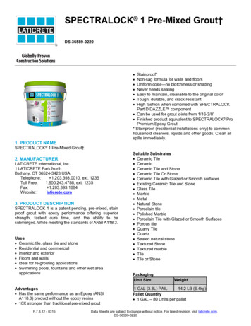
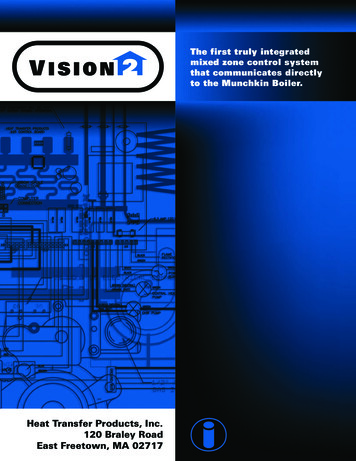
TECHNICAL FEATURE Fundamentals at WorkFIGURE 3 Primary and secondary airstreams.Primary AirPrimary AirIt is important that neither primary or secondary enterthe occupied zone at temperatures or air speeds thatwould be considered uncomfortable.Secondary AirSecondaryAirFIGURE 4 Jet collisions.“L”“L” 3 ftT50Comfort Zone9 ft6 ftIt is reduced the farther away thejet is from the air outlet. If the jetis cooler, and thus denser, than theroom air, it will detach from the ceiling when the forward momentum ofthe supply jet is less than the downwards buoyancy force. If the buoyancy force is great enough, the supply jet may enter the occupied zonewith an objectionable temperatureor velocity. This effect is predictableand should be considered by thedesigner.Throw, defined as the projectionof an air device, is the distance theair travels before it slows to a specified air speed. Often manufacturers14ASHRAE JOURNALashrae.orgreport throws to air speeds of 50 fpm(0.25 m/s), 100 fpm (0.5 m/s), and150 fpm (0.76 m/s). These throws aremost often reported for isothermalair, which is simply supply air that isthe same temperature as the roomair, as isothermal throw is moreeasily measured and is used for airdiffusion performance index (ADPI)calculations, as we will see later.If a diffuser has too short a throw,such as at low airflow rates in coolingmode, it may detach from the ceilingbefore it has entrained enough air towarm up and mix enough with theroom air. The result is that the coldair will fall into the space. This is oftenJ U LY 2 0 1 5referred to as “dumping,” although themore correct term is “excessive drop.”But if opposing jets have too high ofairflows, they may collide and enterthe occupied zone at air speeds thatmay be perceived as a draft. For designengineers, it is a matter of finding theright balance between preventingexcessive drop and maintaining theentrainment rate.Figure 3 shows the total airstreamfrom a ceiling-mounted air outlet.The shaded areas are secondary air,or air that has been significantlymixed with room air. Figure 4 showswhat happens when opposing jetscollide.It is important that the jet notenter the occupied zone until sufficiently tempered and slowed.Standard 55-2013 requires the use ofan elevated air speed analysis whenair speeds exceed 40 fpm (0.20 m/s).The ASHRAE Handbook—Fundamental’sSpace Air Diffusion chapter recommends not exceeding 50 fpm (0.25m/s), and the ADPI method excludespoints in excess of 70 fpm (0.35 m/s).Using manufacturer’s catalog data,engineers are able to select devicesthat will have long enough throws atminimum airflows to avoid excessive drop while spacing diffusers farenough apart to avoid excessive collisions. While manufacturers usuallyreport throws to 50 fpm (0.25 m/s) intheir catalogs, in selection softwarethe desired terminal velocity is usually a selectable parameter.The distance from a diffuser to theedge of the space it is designed toserve is designated as the “characteristic length” or “L.” Therefore, identical diffusers with the same flow ratesare spaced 2 L apart. To avoid draftsin the occupied zone, a good rule ofthumb is that diffusers should be
Advertisement formerly in this space.
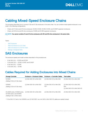
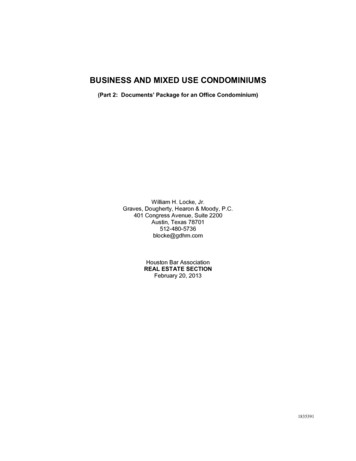
TECHNICAL FEATURE Fundamentals at Workspaced so that at the designed maximum airflow, a 50 fpm throw (T50) isno greater than L plus the distancefrom 6 ft to the room height, asshown in Figure 4.Furthermore, while it mightappear that higher discharge velocities equal greater induction ratesand longer throws, this is not alwaysthe case. Mass effect must be considered because at some point masswill overcome velocity and determine the throw. Different supplyair outlets will perform in differentways. Higher discharge velocitieswill mean greater required systemair pressures and higher fan energy,and usually produce greater soundlevels. We will talk more about whenmore sound production can actuallybe a good thing.In addition to aerodynamic considerations, there are two other performance issues to be considered:pressure and acoustics.PressureThe HVAC system’s fan needs toprovide enough pressure to deliverair to the outlets as well as overcomethe resistance created by the diffuser.In addition, the fan energy also creates room air motion, and pushes airback to the air handler through theair inlets and the return ducts.Air pressure is characterized bythree values: Static pressure is the force perunit area exerted by a fluid. It ismeasured at a 90 degree angle to theflow’s direction, traditionally witha static tube connected to a water-,mercury-, or red gauge oil-filledmanometer. Velocity pressure is the kinetic energy of the fluid flow. It ismeasured by subtracting the static16ASHRAE JOURNALashrae.orgpressure from the stagnation (total)pressure, traditionally with a concentric pitot-static tube. Total pressure is the sum of thestatic and velocity pressures.Total pressure is the measure of theenergy in moving air within a duct,remaining fairly constant, less friction effects. Most air diffuser manufacturers present catalog data onstatic and total pressure losses over arange of airflows (with velocity pressure being the difference betweenthe two). In a duct, velocity pressuresare traditionally measured with apitot-static tube and manometer asdepicted in Figure 5. The pitot tube’sopening on the end reads total pressure (sometimes called stagnationpressure), while the openings on theside measure static pressure. By connecting each of the connections onthe pitot tube to opposite ends of amanometer, it will display the velocity pressure, which is easily convertedto air velocity. Air velocity multipliedby duct area gives the airflow rate.AcousticsWe will discuss acoustics in detailin a following article, “Basics ofApplied Acoustics.” For the moment,however, we need to understandthat in reporting sound producedby air outlets that manufacturersare required to use 10 diametersof straight supply duct attached tothe air device. In the real world,this almost never happens. Studies(reported in “Effects of TypicalInlet Conditions on Air OutletPerformance,” ASHRAE Journal, April2012) show the effect that real-lifeinlet conditions have on acousticperformance. Using flex duct orhard elbows can increase the soundproduced by an outlet (on theJ U LY 2 0 1 5FIGURE 5 Pitot tube.PsPTPitot TubeConnecting TubingPsPV Difference in Liquid LevelPT – PS PVPTGlass Manometer Tubeaverage of a noise criteria [NC] of 5)compared to manufacturer’s catalogdata obtained per the above.Sound generated by a diffuser is created by mixing air. As a general rule,the louder an air device is, the betterit works. By selecting the quietest possible diffuser, it may mean it is notmixing as well as it could. With variable volume designs, which we willdescribe in detail in a following article,cooling airflow rates are at their highest on
He is a member of SSPC 55-2013, SPC 129 and consultant to SSPC 62.1-2013. BY DAN INT-HOUT, FELLOW ASHRAE asics of Well-Mixed Room Air Distribution This article is the rst of three I hae written for the Fundamentals at Work series. This one will coer air distribution for well-mixed systems, the most common appli - cation in commercial and institutional buildings in the .S. It will be followed .