Transcription
JAFNPPIMPROVED STANDARD TECHNICALSPECIFICATIONS (ISTS) CONVERSIONITS: 3.7.4Control Room Air Conditioning (AC) SystemMARKUP OF NUREG-1433, REVISION 1, BASES
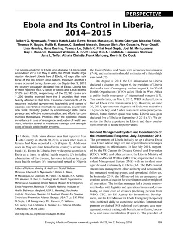
Control'Room AC#f SystemB 3.7. B 3.7PLANT SYSTEMSB 3.7.0 OControl Room Air Conditioning (AC) lSystem(iBASESBACKGROUND7The jControl Room AC System provides temperature controlfor the control room IgionntrThe &Control Room ACISytem consists of tworedundant subsystems that provide cooling 4hOTIiflJ grecirculated control room air. Each subsystem consists ofcoils, fans, chillers, compressors,ductwork, dampers, and instrumentation and controls toprovide for control room temperature control.StcoolingThe jControl Room ACb System is designed to provide acontrolled environment under both normal and accidentconditions. A single subsystem provides the rit ure.roo-mhtemperature control to maintain a suitablThne persons.ofoccupancysustainedaforenvironmentdesign conditions for the control room environnt are 7 Flative humtditv.4 The fControl Rom AC ysteandoperation n maintaining the control room temperature isdiscussed in the FSAR, Section D P (Ref. 1).)[.AImAPPLICAIRL'FSAFETY WALYSESThe desion basis of the jControl Room ACt System is tomaintain the control room temperature for a 39 dayI(Oilcontinuous occupancy.The tControl Room ACI System components are arranged inredundant safet related subsystems. During emergencyoperation, the Control Room ACO System maintains aOPERABILITY ofhaitable enviromnt and euresEEcomponents in the control room. A single failure of alosscomponent of the Control Room ACI System, assuming aof offslte power, does not impair the ability of the systemto perform its design function. Redundant detectors andcontrols are provided for control room temperature control.The lControl Rom ACQ System is designed in accordance withSeismic Category I requirements. The (Control Room ACISystem is capable of removing sensible and latent heat loadsfrom the control room, including consideration of equipment(continued)BWR/4411B 3.7-25Cire-1if 0y) 0-
Z7INSERT BKGD-1while the Control Room Emergency Ventilation Air Supply (CREVAS) System (amode of the Control Room AC) provides a radiologically controlled environment(refer to the Bases of for LCO 3.7.3. "Control Room Emergency Ventilation AirSupply (CREVAS) System).S2INSERTBKGD-2This can be accomplished when a control room chiller is providing the coolingmedium to the cooling coils of an air handling unit. The control roomchillers are non-safety related; however, the Control Room AC System stillmeets safety-related QA Category I requirements when the Emergency ServiceWater System is aligned to directly supply the cooling coils. The resultingService Watermaximum Control Room environmental conditions when the Emergency0 F assuming temlake temperature of 85 0 F. This satisfies the OPERABILITY requirements of theControl Room equipment.Insert Page 3.7-25
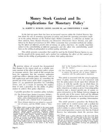
ýControl Room ACb SystemB 3 7.8BASESheat loads and personnel occupancy requirements to ensureequipment OPERABILITY. prdAPPLICABLESAFETY ANALYSES(continued)The lControl Room ACt'.istem satisfies Criterion 3 o 1o6-0 CrA -a-0-3'(. 6c) (?-)(.* ijFa redundant subsystems of the OContrelTwoRoom ACI System are required to be OPERABLE to ensure thatat least one is available, assuming a singleofailurecould\disables the other subsystem. Total system failureresult in the equipment operating temperature exceedinglimits.LCO'-*-)when theThe jControl Room AC eSystem is considered sindividualThes;et subsystems.temeraureare OPEALE in'bothS Eu I r i ductwork, dampers, and associatedinstrumentation and controls.*.*.'In NODE 1, 2, or 3, the jControl Room ACf-Sytem must bewillOPERABLE to ensure that the control room entnot exceedroom isolation.APPLICABILITYIn NODES 4 and 5, the probability and consequences of aandDesign Basis Accident are reduced due to the pressuretemperature limitations in these MODES. Therefore,is notmaintaining the (Control Room ACI System OPERABLEsituationsrequired in NODE 4 or 5, except for the followingunder which significant radioactive releases can bepostulated:a.During operations with a potential for draining thereactor vessel (OPDRVs);b.During CORE ALTERATIONS; andc.During movement of irradiated fuel assemblies in the/e econdaryt containment.(continued)BWR/4 STS8 3.7-26Rev 1, 04/07/95:
.0INSERT LCOThe cooling coils of the air handling units may be cooled by the Control Roomchillers, but to satisfy this LCO, the Emergency Service Water System must becapable of alignment to provide cooling water directly to the cooling coils.Insert Page 3.7-26
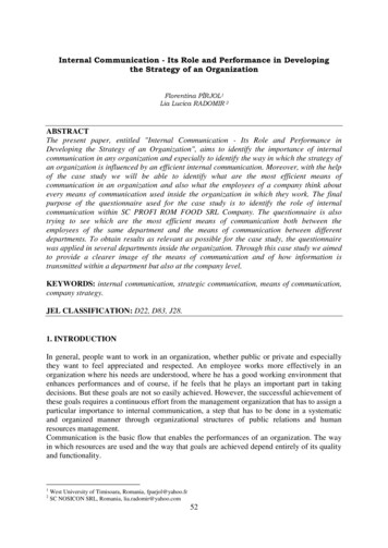
/#Control Room ACJ 8Systeq3.7.FrBASES(continued)ACTIONSA.lWith one &control room AC6 subsystem inoperable, theeinoperable tcontrol room ACI subsystem must be estored too.OPERABLE status within 30 days. With thein thisACProomlcontrolOPERABLEremainingcondition, thesubsystem is adequate to perform the control room airconditioning function. However, the overall reliability isreduced because a singleJ failure in the OPERABLE subsystemcould result in loss of the control room air conditioningfunction. The 30 day Completion Time is based on the lowprobability of an event occurring requiring control roomisolation, the consideration that the remaining subsystemcan provide the required protection, and the availability ofalternate safety and nonsafety cooling methods.In NODE 1, 2, or 3, if the inoperable icontrol room ACsubsystem cannot be restored to OPERABLE status within theust be place in/aassociated Completion Tim, the 1this status, theachieveTorisk.minimizesthatNODEmust be placed in at least NODE 3 within 12 hours and inMODE 4 within 36 hours. The allowed Completion Times arereasonable, based on operating experience, to reach therequired Drcondttons from full power conditions in ansystems.orderly manner andywih94 challenging 4ý5.P1i oC.I. C.2.1.C.2.2, and C.2.3./he Required Actions of Condition C are modified by a Note"indicating that LCO 3.0.3 does not apply. If movingirradiated fuel assemblies while-in NODE 1, 2, or 3, thefuel movement is independent of reactor operations.Therefore, inability to suspend movement ofirradiated fuelassemblies is not sufficient reason to require a reactorshutdown.During movement of irradiated fuel assemblies in the4secondaryl containment, during CORE ALTERATIONS -or during-/OPDRVs, if Required Action A.1 cannot be completed withinthe required Completion Time, -the OPERABLE 1control room A;0subsystem may be-placed immediately in operation. Thisaction ensures that the remaining subsystem is OPERABLE,(continued)B 3.7-27D&ER/4 STSRev 1, 04/07195It1
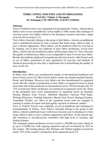
t ontrol Room ACystemB 3.7.9BASESACTIONSCA. C.2.1. C.2.2. and C.2.3(continued)that no failures that would prevent actuation will occur,and that any active failure will be readily detected.An alternative to Required Action C.1 is to immediatelysuspend activities that present a potential for releasingradioactivity that might require isolation of the controlroom. This places the GM nika condition that minimizesrisk.If applicable, 10RE ALTERATIONS and movement of irradiatedfuel assemblies inthe Isecondaryf containment-IMusi.shallsuspended itmediately. Suspension of these activitiesnot preclude completion of movement of a component to a safeposition. Also, if applicable, actionO must be initiatedimmediately to suspend OPDRVs to minimize the probability ofa vessel draindown and subsequent potential for fissionproduct release. Action must continue until the OPDRVs aresuspended.IfIfboth #control room AC.Esubsystems adE noperabl e inmay not beytNODE 1,s 2, or 3, the IControl Rom Acapable of performing the intended function.be entered imoediately.inbiiLCyIOU 3.0.3 mstI'ev(*d t(41v t*Il'"E.ITherefore,E.2. and E.3./heRequired Actions of Condition E are modified by a Noteindicating that LCD 3.0.3 does not apply. If movingirradiated fuel assemblies while in NODE 1, 2, or 3, thefuel movement is independent of reactor operations.Therefore, inability to suspend movement of. irradiated fuelassemblies is not a sufficient reason to require a reactorshutdown.During-movement of irradiated fuel assemblies in theIsecondary* containment, during CORE ALTERATIONS, or duringOPORVs, with two Ocontrol room AC*j subsystem inoperable,action must be taken immediately to suspend activities thatpresent a potential for releasing radioactivity that might(continued)BNR/4 STSB 3.7-28Rev 1, 04/07/95
/Room AC6 System(.ControlB 3.74BASESACTIONSEa.n-(continued)require isolation of the control room.in a condition that minimizes risk.This places theIf applicable, ,ORE ALTERATIONS an* handling of irradiatedffuel in the oecondar.* containment must be suspendednotshallactivitiestheseofimmediately. Suspensionpreclude completion of movement of a component to a safe (initiated)gýposition. Also, if applicable, actionj' must telyfissionforpotentiala vessel draindown and subsequentareproduct release. Action# must continue until the biIity of theThis SR verifies that the heat removcontrolroom heat loadsystem is sufficient to remove theZof aassumed in the Isafety analysesTZ The SR consists(iMonhnThecombination of testing and calculation.ofFrequency is appropriate since signifiant d adationtimethisoverexpectthe TControl Room AQSyste is not.,period.'-BVR/4 STSB 3.7-29Rev 1, 04/07/95
JiJAFNPPIMPROVED STANDARD TECHNICALSPECIFICATIONS (ISTS) CONVERSIONITS: 3.7.4Control Room Air Conditioning (AC) SystemJUSTIFICATION FOR DIFFERENCES (JFDs)FROM NUREG-1433, REVISION 1, BASES
JUSTIFICATION FOR DIFFERENCES FROM NUREG-1433. REVISION 1ITS BASES: 3.7.4 - CONTROL ROOM AIR CONDITIONING (AC) SYSTEMRETENTION OF EXISTING REOUIREMENT (CLB)NonePLANT-SPECIFIC WORDING PREFERENCE OR MINOR EDITORIAL IMPROVEMENT (PA)PAlThe brackets have been removed and the proper plant specific informationhas been provided.PA2ISTS 3.7.5 has been renumbered as ISTS 3.7.4 to reflect deletion of ISTS3.7.3. The Surveillance has been renumbered as a result of this change.PA3Changes have been made (additions, deletions, and/or changes to theNUREG) to reflect the plant specific nomenclature.PA4Editorial change made for enhanced clarity or to be consistent withsimilar statements in other places in the Bases.PA5Editorial change made to be consistent with the Specification.PLANT-SPECIFIC DIFFERENCE IN THE DESIGN (DB)DB1Changes have been made to reflect the plant specific design andanalysis.DB2The brackets have been removed and the proper plant specific referencesprovided.DB3The design does not include redundant heating coils therefore referenceto "heating" and "heating coils" have been deleted. However, a heateris located in the ductwork associated with each Control Room area andeach heater is supplied by a safety related power supply. This detailwas added to the Background Section.DIFFERENCE BASED ON AN APPROVED TRAVELER (TA)NoneDIFFERENCE BASED ON A SUBMITTED. BUT PENDING TRAVELER (TP)NoneJAFNPPPage 1 of 2Revision A
JUSTIFICATION FOR DIFFERENCES FROM NUREG-1433. REVISION 1ITS BASES: 3.7.4 - CONTROL ROOM AIR CONDITIONING (AC) SYSTEMDIFFERENCE FOR ANY REASON OTHER THAN THE ABOVE (X)X1NUREG-1433, Revision 1, Bases reference to "the NRC Policy Statement"has been replaced with 10 CFR 50.36(c)(2)(ii), in accordance with 60 FR36953 effective August 18. 1995.X2The bracketed Surveillance Frequency of 18 months in ITS SR 3.7.4.1 hasbeen removed and the Frequency changed to 24 months in conjunction withthe current operating cycle. This proposed Frequency is consideredadequate since significant degradation of the Control Room AC System isnot expected over this time period.JAFNPPPage 2 of 2Revision A
JAFNPPIMPROVED STANDARD TECHNICALSPECIFICATIONS (ISTS) CONVERSIONITS: 3.7.4Control Room Air Conditioning (AC) SystemRETYPED PROPOSED IMPROVED TECHNICALSPECIFICATIONS (ITS) AND BASES
Control Room AC System3.7.43.7 PLANT SYSTEMS3.7.4Control Room Air Conditioning (AC) SystemLCO 3.7.4Two control room AC subsystems shall be OPERABLE.APPLICABILITY:MODES 1, 2, and 3,During movement of irradiated fuel assemblies in thesecondary containment,During CoreALTERATIONS,During operations with a potential for draining the reactorvessel (OPDRVs).ACTIONSREQUIRED ACTIONCONDITIONCOMPLETION TIMEA. One control room ACsubsystem inoperable.A.1Restore control roomAC subsystem toOPERABLE status.30 daysB. Required Action andassociated CompletionTime of Condition Anot met in MODE 1. 2,or 3.B.1Be in MODE 3.12 hoursBe in MODE 4.36 hoursANDB.2(continued)JAFNPP3.7-11Amendment
.0Control Room AC System3.7.4ACTIONS(continued)REQUIRED ACTIONCONDITIONC. Required Action and- ----------- NOTE -----------LCO 3.0.3 is not applicable.associated Completion.Time of Condition Anot met duringPlace OPERABLEmovement of irradiated C.1control room ACfuel assemblies in thesubsystem insecondary containment,operation.during COREALTERATIONS, or duringOROPDRVs.COMPLETION TIMEImmediatelySuspend movement ofirradiated fuelassemblies in thesecondarycontainment.ImmediatelySuspend COREALTERATIONS.ImmediatelyC.2.3Initiate action tosuspend OPDRVs.ImmediatelyD.1Enter LCO 3.0.3.ImmediatelyC.2.1ANDC.2.2ANDD. Two control room ACsubsystems inoperablein MODE 1, 2, or 3.(continued)JAFNPP3.7-12Amendment
.0 ,Control Room AC System3.7.4ACTIONS(continued)REQUIRED ACTIONCONDITIONE. Two control room ACsubsystems inoperableduring movement ofirradiated fuelassemblies in thesecondary containment,during COREALTERATIONS, or duringOPDRVs.COMPLETION TIME. NOTE -----------LCO 3.0.3 is not applicable.E.1Suspend movement ofirradiated fuelassemblies in thesecondarycontainment.ImmediatelySuspend COREALTERATIONS.ImmediatelyInitiate action tosuspend OPDRVs.ImmediatelyANDE.2ANDE.3SURVEILLANCE REQUIREMENTSSURVEI LLANCESR3.7.4.1JAFNPPVerify each control room AC subsystem hasthe capability to remove the assumed heatload.3.7-13FREQUENCY24 monthsAmendment
Control Room AC SystemB 3.7.4B 3.7PLANT SYSTEMSB 3.7.4 Control Room Air Conditioning (AC) SystemBASESBACKGROUNDThe Control Room AC System provides temperature control forthe control room while the Control Room EmergencyVentilation Air Supply (CREVAS) System (a mode of theControl Room AC) provides a radiologically controlledenvironment (refer to the Bases of for LCO 3.7.3, "ControlRoom Emergency Ventilation Air Supply (CREVAS) System").The Control Room AC System consists of two, redundantsubsystems that provide cooling of recirculated control roomair. Each subsystem consists of cooling coils, fans,chillers, compressors, ductwork, dampers, andinstrumentation and controls to provide for control roomtemperature control. A heater is located in the ductworkassociated with each control room area.The Control Room AC System is designed to provide acontrolled environment under both normal and accidentconditions. A single subsystem provides the requiredtemperature control to maintain a suitable control roomenvironment for a sustained occupancy of 20 persons. The 0design conditions for the control room environment are 75 Fand 50% relative humidity. This can be accomplished when acontrol room chiller is providing the cooling medium to thecooling coils of an air handling unit. The control roomchillers are non-safety related; however the Control Room ACSystem still meets safety-related QA Category I requirementswhen the Emergency Service Water System is aligned todirectly supply the cooling coils. The resulting maximumcontrol room environmental conditions when the EmergencyService Water System is supplying the air handling unit 0cooling coils is 1047F assuming a lake temperature of 85 F.This satisfies the OPERABILITY requirements of the controlroom equipment. The Control Room AC System operation inmaintaining the control room temperature is discussed in theUFSAR. Section 9.9.3.11 (Ref. 1).(continued)JAFNPPB 3.7-23Revision 0.1
Control Room AC SystemB 3.7.4BASES(continued)APPLICABLESAFETY ANALYSESThe design basis of the Control Room AC System is tomaintain the control room temperature for a 31 daycontinuous occupancy.The Control Room AC System components are arranged inredundant safety related subsystems. During emergencyoperation, the Control Room AC System maintains a habitableenvironment and ensures the OPERABILITY of components in theControl Room. A single active component failure of acomponent of the Control Room AC System, assuming a loss ofoffsite power, does not impair the ability of the system toperform its design function. Redundant detectors andcontrols are provided for Control Room temperature control.The Control Room AC System is designed in accordance withSeismic Category I requirements. The Control Room AC Systemis capable of removing sensible and latent heat loads fromthe Control Room, including consideration of equipment heatloads and personnel occupancy requirements to ensureequipment OPERABILITY.The Control Room AC System satisfies Criterion 3 of10 CFR 50.36(c)(2)(ii) (Ref. 2).LCOTwo redundant subsystems of the Control Room AC System arerequired to be OPERABLE to ensure that at least one isavailable, assuming a single active component failuredisables the other subsystem. Total system failure couldresult in the equipment operating temperature exceedinglimits.The Control Room AC System is considered OPERABLE when theindividual components necessary to maintain the control roomtemperature are OPERABLE in both subsystems. Thesecomponents include the air handling units, recirculationexhaust fans, air handling unit fans, ductwork, dampers, andassociated instrumentation and controls. The cooling coilsof the air handling units may be cooled by the control roomchillers, but to satisfy this LCO the Emergency ServiceSystem must be capable of alignment to provide cooling waterdirectly to the cooling coils.(continued)JAFNPP8B3.7-24Revision 0
Control Room AC SystemB 3.7.4BASES(continued)APPLICABILITYIn MODE 1, 2, or 3, the Control Room AC System must beOPERABLE to ensure that the control room temperature willnot exceed equipment OPERABILITY limits following controlroom isolation.In MODES 4 and 5, the probability and consequences of aDesign Basis Accident are reduced due to the pressure andtemperature limitations in these MODES. Therefore,maintaining the Control Room AC System OPERABLE is notrequired in MODE 4 or 5, except for the following situationsunder which significant radioactive releases can bepostulated:ACTIONSa.During operations with a potential for draining thereactor vessel (OPDRVs);b.During CORE ALTERATIONS; andc.During movement of irradiated fuel assemblies in thesecondary containment.A.1With one control room AC subsystem inoperable, theinoperable control room AC subsystem must be restored toOPERABLE status within 30 days. With the plant in thiscondition, the remaining OPERABLE control room AC subsystemis adequate to perform the control room air conditioningfunction. However, the overall reliability is reducedbecause a single active component failure in the OPERABLEsubsystem could result in loss of the control room airconditioning function. The 30 day Completion Time is basedon the low probability of an event occurring requiringcontrol room isolation, the consideration that the remainingsubsystem can provide the required protection, and theavailability of alternate safety and nonsafety coolingmethods.B.A and B.2In MODE 1, 2, or 3, if the inoperable control room ACsubsystem cannot be restored to OPERABLE status within theassociated Completion Time, the plant must be placed in a(continued)JAFNPPB 3.7-25Revision 0
--Control Room AC SystemB 3.7.4BASESACTIONSB.1 and B.2(continued)MODE that minimizes risk. To achieve this status, the plantmust be placed in at least MODE 3 within 12 hours and inMODE 4 within 36 hours. The allowed Completion
ITS BASES: 3.7.4 - CONTROL ROOM AIR CONDITIONING (AC) SYSTEM DIFFERENCE FOR ANY REASON OTHER THAN THE ABOVE (X) X1 NUREG-1433, Revision 1, Bases reference to "the NRC Policy Statement" has been replaced with 10 CFR 50.36(c)(2)(ii), in accordance with 60 FR 36953 effective August 18. 1995. .