Transcription
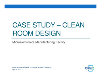
CASE STUDY – CLEANROOM DESIGNMicroelectronics Manufacturing FacilityRocky Mountain ASHRAE 25th Annual Technical ConferenceApril 28, 2017
Agenda Terminology Clean Room Design BasicsISO ClassificationsFiltration and air-change ratesFilter basics Case StudyFacility descriptionProject design criteriaHVAC system descriptionsEnergy efficiency considerations Conclusion / Q & A
Relevant Terminology1. ACH/ACR: Air changes per hour / air change rate2. Air Lock: A transitional room between two other rooms of differentcleanliness.3. Challenge: An airborne dispersion of particles used to test filter integrity andefficiency.4. Cleanroom: A room in which the concentration of airborne particles iscontrolled, and which is constructed and used in a manner to minimize theintroduction, generation, and retention of particles inside the room and inwhich other relevant parameters, e.g. temperature, humidity and pressureare controlled as necessary (ISO 14644‐1 definition).5. DOP: Dioctyl phthalate, and aerosol used for filter challenge.6. FS‐209: Federal Standard recommends ACH rate for various classifications.7. HEPA: High‐efficiency particular air filter.8. ISO 14644‐1: International Organization for Standardization standard thatdefines airborne particulate cleanliness classifications9. Unidirectional (Laminar) flow: Air flowing at a constant and uniform velocityand direction.10. ULPA: Ultra‐low penetration air filter11. Particle concentration: The number of particles per unit of air.
Airborne ParticulatesPerspective: 98% of all particles found in indoor air are smaller than 1 micron in size.
Filter MERV RatingsULPA Filters MERV19‐20MERV 13 is standard for aClass A office designHEPA filters MERV17‐18
Filter MediaOlder generations ofHEPA filters usedaluminum pleatseparatorsGlass fiber papertechnologyToday’s micro‐pleatmedia technologyallows for lowerpressure drop andreduced filter mediadepth
Airborne Particulate CleanlinessClassificationsISO 14644‐1ISO ClassFEDERAL STANDARD 209EEnglishMetricISO 31M1.5ISO 410M2.5ISO 5100M3.5ISO 61,000M4.5ISO 710,000M5.5ISO 8100,000M6.5ISO 9N/AN/AISO 1Increasing CleanlinessISO 2Standard 209E classifications are out‐of‐date.This standard was officially retired in 2001.
Airborne Particulate CleanlinessNumber of Particles per Cubic Meter by Micrometer SizeCLASS0.1 micron 0.2 micron 0.3 micron 0.5 micron1 micron5 0,0008,320,000293,000Perspective: A strand of human hair is about 40‐100 microns in diameter.
Air Change Rates / Ceiling HEPACoverageUni‐directional air flowin cleanroom applies toISO 6 and above300 ACH 45 CFM/SF ina cleanroom with a 9’ceiling% of cleanroomceiling area occupiedby filter modules
Case Study Introductory NotesProject specifics – location, company, etc. areconfidential.Photos used in this presentation are generic,unless otherwise noted.The Case Study project was delivered to theOwner as a design‐assist, with contractorinvolvement early in the design process.
Design Criteria – Clean RoomISO Class 6 Environment: 36,000 SF open‐bay type cleanroom Positive room pressure controlled to 0.05” WC Room conditions at 69 F and 40% RH Minimum of 120 air‐changes per hour 33% ceiling HEPA coverage Unidirectional vertical airflow 12’ ceiling heightRoom features: Smooth, cleanable interior surfaces Gasketed grid ceiling with luminaires, HEPA modules, and systemscomponents (sprinkler heads, smoke detectors, etc.), smoke exhaust grilles Perforated floor serves as return air path Wafer manufacturing tools with specialized solvent and acid exhaust systems
HVAC Design – Clean RoomMake‐up Air AHUs: 100% outside air delivery to plenum Temperature and humidity control ofmake‐up air (6) units, each sized for 30,000 CFM Make‐up air flow is 5 CFM/SF, or 25 ACH.Recirculating AHUs: (40) units, each sized for 24,000 CFM Recirculated air flow is 26.7 CFM/SF, or133 ACH. Powder‐coated finishExhaust Systems: Acid Exhaust (2.8 CFM/SF), with scrubbers and N 1 redundancy Solvent Exhaust (0.8 CFM/SF), N 1 redundancy. Smoke Exhaust (2.7 CFM/SF)
Building Cross-sectionMake‐up AHU’sRecirculating AHU’sISO Class 6CleanroomPerforated floorslab for RA pathThis multi‐level configuration is often applied tomore stringent ISO cleanroom classifications.Ducted HEPAterminals
Manufacturing Level Ceiling PlanHEPA filter modulearrangement in a 2’X 4’ clean‐roomsealed ceiling gridOverall CeilingHEPA coverage is33%
Filter TerminalsSA connection –AHU supply fanprovidesrequired staticFilter mediaKnife‐edge sealwith gel gasketBalancing damper,accessible from themanufacturing level
Interstitial Level PlanActual project photoSupply air plenums areconnected to provide a level ofredundancy betweenrecirculation units.Supply air plenums withmultiple take‐off fittingsto HEPA ceiling modules
Fan Attic Level PlanMake‐up air units,with outside airhoods aboveThe entire fanattic level servesas a mixed airplenum.Exhaust mainsRecirculated air units, withdownward discharge tosupply plenums at theInterstitial level.
Fan Attic LevelAHU supportstructureSupply air plenum(flex ducts to HEPAsnot shown).Recirculated air units,supported from structuralframework.Smoke exhaust
Clean Room Make-up Air UnitsOutside airfrom roof hoodUnits are scheduledfor 8.0” TSP, andonly 0.75” ESP.Pre‐ andintermediatefiltration8‐row, 10 FPI dehumidificationcoil sized for 400 FPM facevelocity and 1.13” DP8‐row, 8 FPI cooling coil sizedfor 400 FPM face velocity and0.83” DPDirect‐drive fanarray (4 fans) (535CFM/BHP), N 1Outside air make‐up AHUdesign with completetemperature and humiditycontrol.Air is HEPA filtered tomaximize the service lifeof terminal HEPAs
Fan Array TechnologyMany advantages over single‐fan systems: Equipment redundancyLess vibrationLower noiseLess space requiredTighter duty selectionDirect drive fans – no beltloss
Psychrometrics – Make-up Air UnitsMake‐up Air AHUcooling coil:EA 85 F db/70 F wbLA 52 F db/52 F wbMake‐up Air AHUdehumidification coil:EA 53 F db/53 F wbLA 42 F db/42 F wbOutside air conditions atMaximum wb temp andcoincident db tempMake‐up Air AHUReheat Coil:EA 41 F dbLA 72 F dbRoom conditions:69 F db/40% RH
Clean Room Recirculation UnitsSimple, low‐pressurerecirculating AHUdesign with very lowunit pressure dropUnits are scheduledfor 3.0” TSP, whichincludes terminalHEPA DP.3‐row, 8 FPI coolingcoil sized for 400 FPMmaximum facevelocity and 0.17” DPDirect‐drive fan withcustom wheel width(1500 CFM/BHP)
Psychrometrics – Recirculation UnitsRecirculating AHUcooling coil:EA 72 F db/59 F wbLA 64 F db/57 F wbRoom conditions:69 F db/40% RHNote:The recirculating AHU Coolingprocess is 100% sensiblecooling. Condensate does notcollect on the cooling coil
Energy Efficiency ConsiderationsCleanrooms can easily be 50X more energy‐intensive than typical office space, and thatis heavily impacted by the fan energyrequired to deliver the prescribed air‐changerate at the required filtration level. Theroom cooling load is often a small fraction ofthe energy demand. Things to prioritize:1. Efficient fan selection – direct‐drive, withcustom wheel selection2. High‐efficiency fan motors3. Low system pressure drop – size ductworkfor low velocity and minimize length ofduct runs4. Low component pressure drop – keep airvelocity (and pressure drop) across coilsand filters as low as practicalFan EnergyCooling EnergyPowerLighting
Other Energy Efficiency ConsiderationsOther design considerations:1. AHU cooling coils are sized for a low face velocity(400 FPM) and air temperature drop (less than 8 F),which allows coil selections to have 3 rows/8 FPI,and minimized pressure drop (0.17” WC) as a result.2. Because cooling coil temperature drop is minimized,chilled water supply temperature can be increased(57 F) during mild and cold weather, which furtherincreases the efficiency of the chilled water plant.3. Pre‐filters: Intended to maximize the life‐span ofthe HEPA terminal filters. 400 FPM face velocity.4. Supply fan speeds are modulated through VFDs as afunction of filter loading.5. Limiting the cleanroom ceiling height to 12’ helpsminimize the CFM required to maintain ACH rates.Chilled water coil
Specialty Exhaust SystemsNote the structureabove is the perforatedfloor /return air pathAcid and solventexhaust systems: Epoxy‐lined stainless‐steelexhaust ductwork withwelded seams andflanged connections.Acid exhaust stream isrouted through ascrubber system prior tobeing discharged at highvelocity vertical plumedischarge at roof level.Actual project photo – Sub-Fab Level
Recommended References: ASHRAE Applications Volume,Chapter 18: Clean Spaces ISO Cleanroom Standards Manufacturer web‐sites:Cam‐fil (filters)Flanders (filters)Price Design Guide (air devices)
Questions?
Thank you!
Contact InformationBarry J. Stamp, PE, LEED APDirector of Engineering ServicesU.S. Engineering om
HVAC Design – Clean Room Make ‐up Air AHUs: 100% outside air delivery to plenum Temperature and humidity control of make‐up air (6) units, each sized for 30,000 CFM Make‐up air flow is 5 CFM/SF, or 25 ACH. Recirculating AHUs: (40) units, each sized for 24,000 CFM Recirculated air flow is 26.7 CFM/SF, or 133 ACH. Powder‐coated finish Exhaust Systems: Acid Exhaust (2.8 CFM/SF), with .