Transcription
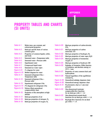
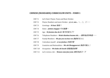
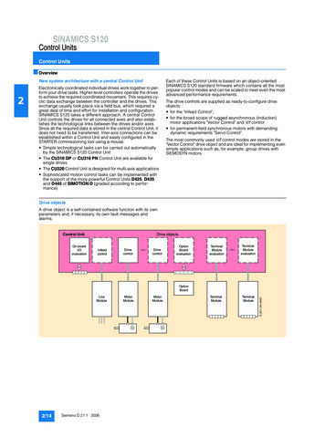
SINAMICS S120Control UnitsControl Units OverviewNew system architecture with a central Control UnitEach of these Control Units is based on an object-orientedSINAMICS S120 standard firmware which contains all the mostpopular control modes and can be scaled to meet even the mostadvanced performance requirements.The drive controls are supplied as ready-to-configure driveobjects: for the "Infeed Control", for the broad scope of rugged asynchronous (induction)motor applications "Vector Control" and V/f control for permanent-field synchronous motors with demandingdynamic requirements "Servo Control".The most commonly used V/f control modes are stored in the"Vector Control" drive object and are ideal for implementing evensimple applications such as, for example, group drives withSIEMOSYN motors.Drive objectsA drive object is a self-contained software function with its ownparameters and, if necessary, its own fault messages andalarms.Control UnitOn-boardI/OevaluationDrive oduleevaluationOptionBoardLineModule2/14Siemens D 21.1 · duleG D211 EN 000572Electronically coordinated individual drives work together to perform your drive tasks. Higher-level controllers operate the drivesto achieve the required coordinated movement. This requires cyclic data exchange between the controller and the drives. Thisexchange usually took place via a field bus, which required agreat deal of time and effort for installation and configuration.SINAMICS S120 takes a different approach: A central ControlUnit controls the drives for all connected axes and also establishes the technological links between the drives and/or axes.Since all the required data is stored in the central Control Unit, itdoes not need to be transferred. Inter-axis connections can beestablished within a Control Unit and easily configured in theSTARTER commissioning tool using a mouse. Simple technological tasks can be carried out automaticallyby the SINAMICS S120 Control Unit The CU310 DP or CU310 PN Control Unit are available forsingle drives The CU320 Control Unit is designed for multi-axis applications Sophisticated motion control tasks can be implemented withthe support of the more powerful Control Units D425, D435and D445 of SIMOTION D (graded according to performance)
SINAMICS S120Control UnitsControl Units Overview (continued)Comprehensive package of open-loop and closed-loopcontrol functionsA wide variety of standard functions such as setpoint input, dataset changeover, controller optimization, kinetic buffering, etc.ensure a high degree of operational reliability and excellent flexibility of application.2Overview of key open-loop and closed-loop control functions:Closed-loop controltypes S120Open-loop controltypes S120Main functions S120for booksize/chassisComment, noteInfeed Control Booksize- Current control with/withoutmains sensor- VDC control with/withoutmains sensor Chassis- Current control with mainssensor- VDC control with mainssensor Booksize- Smart Line Modules canbe selected Chassis- Basic Line Modules canbe selected Mains identification Controller optimization Harmonics filter Automatic restartThe mains sensor is the VSM 10Voltage Sensing Module; "current" is the line current; 3-phasewith line frequencyVector Control Asynchronous motor- Torque control with/withoutencoder- Speed control with/withoutencoder Torque motor- Torque control with encoder- Speed control with/withoutencoder For asynchronous and torquemotors- Position control withencoder- Linear/paraboliccharacteristic- Fixed-frequencycharacteristic (textiles)- Independent voltagesetpoint input Data set changeover Extended setpoint input Motor identification Current/speed controlleroptimization Technology controller Basic positioner Automatic restart Flying restart with/withoutencoder Kinetic buffering Synchronization DroopMixed operation with V/f controlmodes is possible; it is for thisreason that the V/f controlmodes are stored only once inthe "Vector Control" drive objectPosition control can beselected as a function modulefrom both Servo and Vectormode.Synchronous motors (1FK and1FT) and linear motors can beoperated only in Servo mode.Servo control- Linear/parabolic characteristic- Fixed-frequency characteristic (textiles)- Independent voltagesetpoint input Data set changeover Setpoint input Motor identification Damping application Technology controller Basic positionerMixed operation with V/f controlmodes is possible; it is for thisreason that the V/f controlmodes are stored only once inthe "Vector Control" drive objectPosition control can beselected as a function modulefrom both Servo and Vectormode. Asynchronous motor- Torque control with encoder- Speed control with/withoutencoder Synchronous motor, linear motor and torque motor- Torque control with encoder- Speed control with encoder For all motor types- Position control withencoderTechnology packagesSIMOTION D Control Units support the coordinated motion control of multiple drives. In addition to drive objects, these ControlUnits also offer technology objects such as, for example, "camcontroller", "synchronism", "cam disk" and "temperature control",and these objects are grouped to form technology packages.Users can create their own objects and set up links between allconfigured objects.Siemens D 21.1 · 20062/15
SINAMICS S120Control UnitsControl Units Overview (continued)2BICO technologyDiagnostics optimally supported by trace functionEvery drive object contains a large number of input and outputvariables which can be freely and independently interconnectedusing Binector Connector Technology (BICO). A binector is alogic signal which can assume the value 0 or 1 A connector is anumerical value, e.g. the actual speed or current setpoint.The time characteristics of input and output variables associatedwith drive objects can be measured by the integrated trace function and displayed using the STARTER commissioning tool. Thetrace can record up to 4 signals simultaneously. A recording canbe triggered as a function of freely selectable boundary conditions, e.g. the value of an input or output variable.Function modulesThe "basic positioner" is used for the absolute/relative positioning of linear and rotary axes (modulo) with motor encoders (indirect measuring system) or machine encoders (direct measuringsystem). The "technology controller" is designed as a PID controller. It is suitable for implementing controls for regulating variables such as fill level, temperature, tension, pressure, flow rateand dancer position.Integrated safety functionsThe Control Units support safety functions such as "Safe standstill“ (STO Safe Torque Off)CompactFlash cardThe functions of the SINAMICS S120 drives are stored on aCompactFlash card. This card contains the firmware and parameter settings for all drives in the form of a project. TheCompactFlash card can also hold additional projects, whichmeans that the correct project can be accessed immediatelywhen series machines of different types are commissioned.When the Control Unit has booted, the data on the CompactFlash card are read and loaded to the RAM.The firmware is organized in objects. Drive objects are used toimplement open-loop and closed-loop control functions for LineModules, Motor Modules, Power Modules and other systemcomponents connected by DRIVE-CLiQ.2/16Siemens D 21.1 · 2006
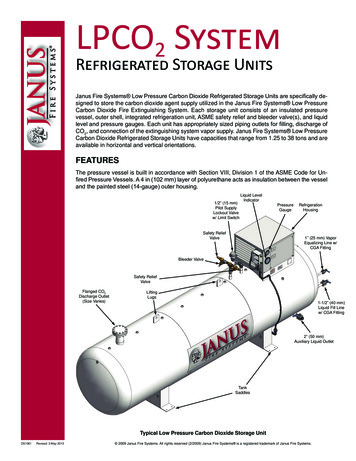
SINAMICS S120Control UnitsCU310 DP Control Unit Overview Selection and ordering dataDescriptionOrder No.CU310 DP Control Unit(without CompactFlash card)6SL3040-0LA00-0AA02 AccessoriesDescriptionOrder No.PROFIBUS connectorwithout PG/PC connection6ES7972-0BA41-0XA0PROFIBUS connectorwith PG/PC connection6ES7972-0BB41-0XA0STARTER commissioning tool6SL3072-0AA00-0AG0 IntegrationThe CU310 DP Control Unit drives Power Modules in blocksizeformat via the PM-IF interface. In this case, other DRIVE-CLiQcomponents such as Sensor or Terminal Modules, can be connected to the DRIVE-CLiQ socket on the CU310 DP Control Unit.Power Modules in chassis format are driven by the CU310 DPControl Unit via the DRIVE-CLiQ interface. With this option,Sensor and Terminal Modules must be connected to the freeDRIVE-CLiQ sockets on the Power Module.The CU310 DP Control Unit provides the communications andopenloop/closed-loop control functions for a Power Module.The CU310 DP combined with a Power Module andCompactFlash card creates a powerful single axis AC drivewith a PROFIBUS interface to a higher-level control. DesignCU310 DP Control Units feature the following interfaces asstandard: 1 DRIVE-CLiQ socket for communication with otherDRIVE-CLiQ devices, e.g. Sensor or Terminal Modules 1 PM-IF interface for communication with Power Modules inblocksize format 1 interface to the BOP20 Basic Operator Panel 1 PROFIBUS interface with PROFIdrive V4 profile 1 HTL/TTL encoder evaluation circuit 4 parameterizable digital inputs (floating) 4 parameterizable bidirectional digital inputs/digital outputs(non-floating) 1 serial RS232 interface 1 slot for the CompactFlash Card on which firmware andparameters are stored 3 test sockets and one reference ground for commissioningsupport 1 connection for the electronics power supply via the 24 V DCpower supply connector 1 PE (protective earth) connectionParameter settings can be changed with the BOP20 BasicOperator Panel. The BOP20 panel can also be snapped onto theCU310 DP Control Unit during operation to perform troubleshooting procedures.The CU310 DP Control Unit and other connected componentsare commissioned and diagnosed with the STARTER commissioning tool.A CU310 DP Control Unit communicates with the higher-levelcontrol system using PROFIBUS and the PROFIdrive V4 profile.The integrated safety functions such as e.g. "Safe Torque Off"( "Safe standstill") must be selected in two channels. Two digitalinputs on the CU310 DP Control Unit are required for this purpose.An external 24 V supply can be connected to the CU310 topower the control unit when the incoming supply to the PowerModule is not energized.The status of the CU310 DP Control Unit is indicated via multicolor LEDs.A BOP20 Basic Operator Panel can also be snapped directlyonto the CU310 DP Control Unit for diagnostic purposes.As the firmware and parameter settings are stored on a plug-inCompactFlash card, the Control Unit can be changed withoutthe need for software tools.Siemens D 21.1 · 20062/17
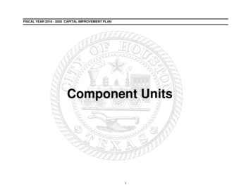
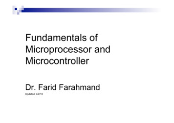
SINAMICS S120Control UnitsCU310 DP Control Unit Integration (continued) 235MX124 serial interface 24 V MMMMPROFIBUSTxD X22X100X23Encoder interfaceX21ext.24 VRxD2DRIVE-CLiQ socket 0MMControl UnitCU310 DPX1201nc2nc3M4 Temp5-Temp6nc7EP 24 V8EP M1PM-IFinterface4)X1211DI 42DI 53DI 64DI 75M22)6M7DI/DO 128DI/DO 13 1)9M10DI/DO 14 1)11DI/DO 15 1)12MCompactFlash card1)2)3)4)Fast inputs (must be shielded)Jumper open, isolation for digital inputs (DI)Can be parameterized individually as input/outputRequired for SafetyConnection example of CU310 DP Control Unit2/18Siemens D 21.1 · 2006G D211 EN 000583)
SINAMICS S120Control UnitsCU310 DP Control Unit Technical dataCU310 DP Control UnitMax. current requirement (at 24 V DC)without taking account of digital outputs and DRIVE-CLiQ supply0.85 AMax. connectable cross section2.5 mm2Max. fuse protection20 ADigital inputs4 x floating digital inputs4 bidirectional non-floating digital inputs/digital outputs Voltage– 3 V to 30 V Low level (an open digital input is interpreted as "low")– 3 V to 5 V High level15 V to 30 V Current consumption (typ. at 24 V DC) Signal propagation delays for digital inputs210 mA1)L H: approx. 50 µsH L: approx. 100 µs Signal propagation delays for high-speed digital inputs1)(high-speed digital inputs can be used for position detection)L H: approx. 5 µsH L: approx. 50 µs Max. connectable cross section0.5 mm2Digital outputs (continued-short-circuit-proof)4 bidirectional non-floating digital inputs/digital outputs Voltage24 V DC Max. load current per digital output 2)500 mA Delay time of the digital outputsapprox. 150 µs Max. connectable cross section0.5 mm2Encoder evaluationTTL or HTL incremental encoders (with adjustable parameters) Cut-off frequency500 kHz Max. cable length for TTL incremental encoder100 m (328 ft) (only bipolar signals permitted) Max. cable length for HTL incremental encoder100 m (328 ft) for unipolar signals300 m (984 ft) for bipolar signalsPower loss 20 WPE connectionOn housing with M5 screwWidth73 mm (2.9 in)Height183.2 mm (7.2 in)Depth89.6 mm (3.5 in)Weight, approx.0.95 kg (2 lb)ApprovalscULus (File No.: E164110)1)2)The specified signal propagation delays refer to the hardware. Theactual reaction time depends on the time slot in which the digital inputor output is processed.In order to use the digital outputs, an external 24 V power supply mustbe connected to terminal X124.Siemens D 21.1 · 20062/19
SINAMICS S120Control UnitsCU310 PN Control Unit Overview Selection and ordering data2DescriptionOrder No.CU310 PN Control Unit(without CompactFlash card)6SL3040-0LA01-0AA0 AccessoriesThe CU310 PN Control Unit is designed for the communicationand open-loop/closed-loop control functions of a PowerModule. The CU310 PN combined with a Power Module andCompactFlash card creates a powerful single axis AC drive.The communication link to the higher-level control is providedby PROFINET IO. DesignCU310 PN Control Unit features the following interfaces asstandard: 1 DRIVE-CLiQ socket for communication with otherDRIVE-CLiQ devices, e.g. Sensor or Terminal Modules 1 PM-IF interface for communication with Power Modules inblocksize format 1 interface to the BOP20 Basic Operator Panel 2 x PROFINET interfaces (RJ45 sockets) with PROFIdrive V4profile 1 HTL/TTL encoder evaluation circuit 4 parameterizable digital inputs (floating) 4 parameterizable bidirectional digita
6SL3040-0LA00-0AA0 Description Order No. PROFIBUS connector without PG/PC connection 6ES7972-0BA41-0XA0 PROFIBUS connector with PG/PC connection 6ES7972-0BB41-0XA0 STARTER commissioning tool 6SL3072-0AA00-0AG0. SINAMICS S120 Control Units CU310 DP Control Unit 2/18 Siemens D 21.1 · 2006 2 Integration (continued) Connection example of CU310 DP Control Unit M