Transcription
International Journal of Trend in Scientific Research and Development (IJTSRD)Volume: 3 Issue: 4 May-Jun 2019 Available Online: www.ijtsrd.com e-ISSN: 2456 - 6470Simulation of Automatic Water Level ControlSystem by using Programmable Logic ControllerMrs Yin Yin Mon, Mrs Win Moet Moet Htwe, Mrs Khin Ei Ei KhineDepartment of Electrical Power Engineering, Technological University, Hmawbi, Yangon, MyanmarHow to cite this paper: Mrs Yin Yin Mon Mrs Win Moet Moet Htwe Mrs Khin EiEi Khine "Simulation of AutomaticWater Level Control System by usingProgrammableLogicController"Published in International Journal ofTrend in Scientific Research andDevelopment(ijtsrd), ISSN: 24566470, Volume-3 Issue-4, June 2019,pp.1621-1628, 172172.pdfCopyright 2019 by author(s) andInternational Journal of Trend inScientific Research and DevelopmentJournal. This is an Open Access articledistributed underthe terms of theCreative CommonsAttribution License (CC BY STRACTThis research focuses on the design and implementation of a PLC-based waterlevel control system. In this research, there are three primary objectives: thewater level indicator circuit design, manual control system of water level controland the PLC based automatic water level control. Float switches cannot be ableto use to indicate the multi water level in the desired control system. Therefore,AND gate based digital electronic water sensor is invented and used in thisproposed not only manual water level control but also PLC based automaticwater level control by dividing in eight steps. Induction motor is used to drivethe pump as a one set package. So, induction motor starting method is selectedaccording to the power rating of motor, type of motor and nature of application.Star-delta starting method is used to reduce the starting current of inductionmotor. For PLC based automatic water level control, Siemens S7-1200 PLC isused to control the desire water level. There are 10 inputs and 10 outputs in theproposed automatic water level control. Ladder diagram programming is usedfor this control.Keywords: AND gate, water sensor, S7-1200, PLCI.INTRODUCTIONNowadays, the process control system is widely used in many different areas,such as waste water treatment, oil and gas purification, chemical, pulp and paperproduction, and food production. In a process control system, the controlleralways plays a significant role to transact the operating conditions of the system.In most industry implementation, the Programmable Logic Controller (PLC) isused due to its advantages, such as fast response, quick and simple trouble-shoot,low cost and high reliability. PLC based automatic waterlevel control system is required to sense the water level inthe tank. Water level sensor circuit is necessary in not onlyto level control system but also to indicate the water levelstatus by pilot light. Digital AND gate LM7408 IC are used inwater level sensor circuit as the main component. Electrodes(copper wire) are used to sense the water level byconducting the current flow as the sensors. It requires 5 and12 V DC VDC power supply for sensor circuits. Manualcontrol is also considered and inserted in this system if theautomatic water level control system is fail by sensor circuitor PLC module. [1]II.BACKGROUND THEORY OF INDUCTIONMOTOR, PUMP AND LOGIC GATEA. Introduction to Induction Motor StarterInduction Motors consume 60% of total electrical energy inindustrialized countries. In industry, more than 90% of theelectrical motors are three phase squirrel-cage inductionmotors. 80% of Induction motor populations are less than15KW, where efficiencies are generally lower and over sizingpossibility is very high. The motor load factor surveyconducted indicates 20% of induction motor population inindustries in organized sector are loaded less than 30% of itsrated capacity.@ IJTSRD Unique Paper ID – IJTSRD25172 The use of squirrel cage induction motor is limited for lowstarting torque application. But in general, due tomaintenance free operation, it is common to use squirrelcage induction motor for High Inertia load application. Thiswill lead to over sizing of motors, which results in excessenergy consumption during normal running condition. Anattempt was made to improve the operating efficiency ofoversized motor in High Inertia load application with thehelp of a special type of starter called Delta-Star Starter. Thisstarter starts the squirrel cage induction motor in DeltaConnection to meet the high starting torque and runs in Starconnection to take care of running torque. [4]B. Star-delta StarterThis type is used for the induction motor, the stator windingof which is nominally delta-connected. If the above windingis reconnected as star, the voltage per phase supplied to eachwinding is reduced by 1/ 3(0.577). This is a simple starter,which can be easily reconfigured. As the voltage per phase indelta connection is , the phase current in each stator windingis (Vs/Zs), where Zs is the impedance of the motor per phaseat standstill or start (stator impedance and rotor impedancereferred to the stator, at standstill). [4]C. Centrifugal PumpCentrifugal pumps have a rotating impeller that throws thewater radically against a casing. The kinetic energy added toVolume – 3 Issue – 4 May-Jun 2019Page: 1621
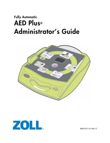
International Journal of Trend in Scientific Research and Development (IJTSRD) @ www.ijtsrd.com eISSN: 2456-6470the water by the impeller is then converted to potentialenergy in the form of pressure or ‘head’ in the diffuser orvolute section. As the water exits the pump through thediffuser, the cross-section increases, causing the velocity(kinetic energy) to reduce and, by conservation of energy,the potential energy is increase. For conventional centrifugalpump designs, high efficiencies are only obtained for lowpumping pressures and hence relatively small pumpingheads of less than about 25 m. Other advantages ofcentrifugal pumps include their simplicity (with a minimumof moving parts) and corresponding reliability, low cost,robustness, tolerance to pumping particulates and lowstarting torque. On the other hand, another potentiallimitation of centrifugal pumps is their inability to be selfpriming, although technology exists for overcoming thisimpediment. Consequently, they are frequently used assubmersible pumps, preferably in conjunction with asubmersible motor. For many years this has been a problem,since the preferred DC motors were not submersible owingto the presence of the brushes.High efficiency can be obtained with small clearances andnarrow passages, but this is undesirable for pump reliabilityand the ability to pump liquids contaminated with particles.In addition, high efficiency can be obtained with a high speedimpeller, which again acts to shorten the life of the pump. Insummary, pumps need to be designed and selected forspecific applications and environments. [4](a)(b)(c)(d)(e)(f)(g)Figure2. various type of gate IC, (a) 7408 Quad 2 inputAND Gates, (b) 7432 Quad 2 input OR Gates, (c) 7400Quad 2 input NAND Gates, (d) 7402 Quad 2 input NORGates, (e) 74266 Quad 2 input XNOR Gates, (f) 7404Hex NOT (Gates Inverters), (g) 74133 Single 13 inputNAND Gate. [3]III.BASIC KNOWLEDGE AND USEFUL FUNCTIONS OFS7-1200A. Basic Requirements for PLC ControlIn order to create or change a program, the followingitems are needed: Programmable logic controller (PLC) Programming device Programming software Connector cable [2]i. Programmable Logic Controller (PLC)Throughout this research the S7-1200 PLC is used because ofits ease of use.Figure1. Centrifugal Pump Operation [4]D. Logic GatesFigure 2, illustrates a selection of the basic gates logic gatesthat are available from a number of manufacturers instandard families of integrated circuits. Each logic family isdesigned so that gates and other logic ICs within that family(and other related families) can be easily combined, andbuilt into larger logic circuits to carry out complex functionswith the minimum of additional components. Typically,standard logic gates are available in14 pin or 16 pin DIL(dual in line) chips. The number of gates per IC variesdepending on the number of inputs per gate. Two-inputgates are common, but if only a single input is required, suchas in the 7404 NOT (or inverter) gates, a 14 pin IC canaccommodate 6 (or Hex) gates. The greatest number ofinputs on a single gate is on the 74133 13 input NAND gate,which is accommodated in a 16 pin package. [3]@ IJTSRD Unique Paper ID – IJTSRD25172 Figure3. S7- 1200 PLC Unit [6]ii. Programming DevicesThe program is created in a programming device (PG) andthen transferred to the PLC. The program for the S7-200 canbe created using a dedicated Siemens SIMATIC S7programming device.Volume – 3 Issue – 4 May-Jun 2019Page: 1622
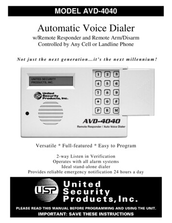
International Journal of Trend in Scientific Research and Development (IJTSRD) @ www.ijtsrd.com eISSN: 2456-6470are required to control the pump motor. Completed circuitdiagram of water level indicator and sensor control circuit isshown in figure 6.Figure4. PG Programming Device for the S7-1200 PLC[6]iii. SoftwareA software program is required in order to tell the PLC whatinstructions it must follow. Programming software istypically PLC specific. A software package for one PLC, or onefamily of PLCs, such as the S7 family, would not be useful onother PLCs. The S7-1200 uses a Windows based softwareprogram called STEP 7- Micro/WIN32. Micro/WIN32 isinstalled on a personal computer in a similar manner to anyother computer software. [5]iv. Connector Cables PPI (Point-to-Point Interface)Connector cables are required to transfer data from theprogramming device to the PLC. Communication can onlytake place when the two devices speak the same language orprotocol. Communication between a Siemens programmingdevice and the S7-1200 is referred to as PPI protocol (pointto- point interface). The S7-1200 uses a 9-pin, D-connector.This is a straight-through serial device that is compatiblewith Siemens programming devices (MPI port) and is astandard connector for other serial interfaces. [2]In the circuit diagram, the eight number of AND gates areused to get the sequential step control according to thenature of water level. LM7408 AND gate IC is used in thiscircuit for both indicators and sensors. Each LM7408 ANDgate IC contains four AND gates as two input gate function.LM7408 AND gate IC operates with 5V DC supply. Relays areoperating with 12VDC supply. So power supply is designedfor both 5V DC and 12VDC fro, 220V AC. To get the desiredDC voltage level of gate ICs, LM7805 voltage regulator IC isused to obtain the 5V DC constant. Relays are supplied byrectifier and filter output directly. Voltage regulator IC is notrequired for relay operation because relay can operatebetween 11 V DC to 15 V DC.1000 μF 25V capacitor is used as a voltage filter to eliminatethe ripple voltage and frequency of rectifier. 10 μF, 16Vcapacitor is used in the output of LM7805 IC to eliminate thenoise voltage signal by surge voltage. C1384 NPN transistorsare used in all relay driver circuit. 10k ohm resistors areused to ground the inputs of AND gates. 330 ohm resistorsare used to limit the LED operating voltage. 10 ohm resistorsare totally 16 numbers and 330 ohm resistors are totally 19numbers in gate circuits. C1384 NPN transistors are totally 3numbers and relays are also totally 3 numbers for the threecontrol states. One blue LED is used to indicate the maximumlevel of water. Two green LEDs are used to indicate theminimum level of water. Three yellow LEDs are used toindicate the middle level of water. Two red LEDs are used toindicate the under limit level of water in the tank.IV.DESIGN AND TESTING OF PROPOED WATERLEVEL CONTROL SYSTEMA. Introduction to Design ConsiderationIn this section, design consideration of hardware and PLCladder program of the water level control system isdescribed. Firstly, hardware system is considered for bothwater level sensor circuit and PLC control. Water levelcontrol system can be divided in three sections such asA. Water level indicator and sensor control circuitB. Manual water level control system by relayC. Automatic water level control system by PLCFigure5. Prototype of automatic water level controlsystemB. Water level indicator and sensor control circuitWater level indicator and sensor control circuit consists ofeight steps to show the water level in the tank. There arethree relay outputs to give the signal to PLC input such as (i)under limit level, (ii) minimum limit level and (iii) maximumlimit level. The under limit level signal is required in thecontrol to avoid the pumping without water in theunderground tank. Maximum and minimum limit level signal@ IJTSRD Unique Paper ID – IJTSRD25172 Figure6. Completed circuit diagram of water levelindicator and sensor control circuitVolume – 3 Issue – 4 May-Jun 2019Page: 1623
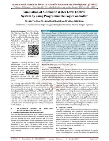
International Journal of Trend in Scientific Research and Development (IJTSRD) @ www.ijtsrd.com eISSN: 2456-6470C. Operation Of Water Level Indicator Control SystemThe flow chart of water level indicator control circuit isshown in figure 7. The water in the tank is used as aconductor to act like sensors. So, the sensors are very simpleand it can save the cost of control circuit.When there is no water in the tank, the under limit sensor isnot actuate and sent a signal to the PLC input module. If thepump motor is running to supply the water in the tank, thewater level will be rise slowly. If the level reach the underlevel limit, the sensor (S1) will actuate and send the signal tothe relay as an ON state. Due to water level increment bypump motor running, it will reach to the next 2nd state. Andthen the sensor (S2) will actuate and red LED is light on.D. Manual water level control systemManual control is used in water pumping system as anauxiliary control if the automatic system is fail to pump thewater due to water level sensor fault. One of the powercircuits of star-delta control is shown in figure 8. Over loadin the power circuit tend to protect the motor winding if theover current occurs at the motor winding. Circuit breaker inthe circuit tends to protect the power line if the faults occurat motor control.If the water level reach to the 3rd state level, the sensor (S3)will actuate and it may turn yellow LED is light on. If thewater level reach to the 4th state level, the sensor (S4) willactuate and it may turn yellow LED is light on. Next, if thewater level reach to the 5th state level, the sensor (S5) willactuate and it may turn yellow LED is light on. Yellow LEDsindicate the middle level of water in the tank.If the water level reach to the 6th state level, the sensor (S6)will actuate and it may turn green LED is light on. If thewater level reach to the 7th state level, the sensor (S7) willactuate and it may turn green LED is light on. And also, relayoutputs the contact to send a minimum water level signal tothe PLC to run the pump motor. Green LEDs indicate theupper level of water in the tank.Figur8. Power Line diagram of water level controlManual control circuit is shown in figure 9. It consists of 6magnetic contactors, 2 timer, 4 pilot light and 4 pushbuttons.If the water level reach to the 8th state level, the sensor (S8)will actuate and it may turn blue LED is light on. At the sametime, relay outputs the contact to send a maximum waterlevel signal to the PLC to stop the pump motor. If the waterlevel refill and under of the 7th state level, the pump motorrestarts to run again to maintain the water level between theminimum and maximum level.Figure7. Flow chart of water level indicator controlcircuit@ IJTSRD Unique Paper ID – IJTSRD25172 Figure9. Manual Control Circuit of water level controlVolume – 3 Issue – 4 May-Jun 2019Page: 1624
International Journal of Trend in Scientific Research and Development (IJTSRD) @ www.ijtsrd.com eISSN: 2456-6470E. Automatic water level control system by PLCFigure10. Flow chart of automatic water level controlIn this research, combination of gate electronic sensor circuit for water level indicator light and pump motor control by PLC isused to get perfect and more reliable control system. The control system of flow chart is shown in figure 10.Siemen S7-1200 PLC is used in control circuit associated with programming software. Ladder diagram language is used inprogram because it is the most familiar language and easy to visual operation in simulation by graphical symbols. Figure 11shows the PLC ladder diagram of automatic water level control system. Figure 12 shows the connection diagram of inputswitch, sensor and output relays and pilot light.@ IJTSRD Unique Paper ID – IJTSRD25172 Volume – 3 Issue – 4 May-Jun 2019Page: 1625
International Journal of Trend in Scientific Research and Development (IJTSRD) @ www.ijtsrd.com eISSN: 2456-6470@ IJTSRD Unique Paper ID – IJTSRD25172 Volume – 3 Issue – 4 May-Jun 2019Page: 1626
International Journal of Trend in Scientific Research and Development (IJTSRD) @ www.ijtsrd.com eISSN: 2456-6470Figure11. PLC ladder diagram program of automatic water level control systemInput ListI0.0 system stop,I0.5 GT min level limit switchI0.1 system start,I0.6 GT max level limit switchI0.2 emergency stop,I0.7 OH min level limit switchI0.3 fail safe switch,I1.0 OH max level limit switchI0.4 quick start,I0.6 GT under level limit switchOutput ListO0.0 System RUN PL,O0.5 GT Pump STOP PLO0.1 System STOP PL,O0.6 MMC2O0.2 MMC1,O0.7 YMC2O0.3 YMC1,O1.0 DMC2O0.4 DMC1,OI0.6 OH Pump STOP PLFigure12. Connection diagram of input switch, sensor and output relays and pilot light@ IJTSRD Unique Paper ID – IJTSRD25172 Volume – 3 Issue – 4 May-Jun 2019Page: 1627
International Journal of Trend in Scientific Research and Development (IJTSRD) @ www.ijtsrd.com eISSN: 2456-6470V.ConclusionsThis research investigates a designing process of PLC basedautomatic water level control system. In this system,Siemens S7-1200 PLC, Star-delta based induction motorstarting control and AND gate IC based water level sensorcircuits are used. In this research, eight steps of water levelare considered as the sample water level indicators. If themore steps are required to indicate the water level accordingto the size of tanks, the AND gate IC can be added in thewater level sensor circuits. PLC based water level controlused in industrial water supply is the most reliable controland the best control for sequential process.ACKNOWLEDGEMENTThe author would like to express her gratitude to Dr. NaySoe Shwe, Professor and Head of Electrical PowerEngineering Department, Technological University(Hmawbi) for his encouragement and helpful suggestion andsupervision. The author wishes to thanks all my colleagues.Thanks are also extended to her dear parents and friends fortheir support.@ IJTSRD Unique Paper ID – IJTSRD25172 REFERENCES[1] April 2016. Water Level Monitoring by UsingPLC.[2] Gebremaryam Alem ,Dr.Krishnanaik Vankdoth,“Automatic Fluid Level Control Using ProgrammableLogic Controller”.[3] Haoqiang Ji, “PLC Programming For A Water �,2017[4] Kharagpur, “Different Types of Starters for InductionMotor (IM)”, 2011[5] W. Bolton, “Programmable logic controllers”. Newnes,2015.[6] Siemens AG, “One hour Primier”, Microsystems SiematicS7- 200, Federal Republic of Germany, (2008).Volume – 3 Issue – 4 May-Jun 2019Page: 1628
Programmable logic controller (PLC) Programming device Programming software Connector cable [2] i. Programmable Logic Controller (PLC) Throughout this research the S7-1200 PLC is used because of its ease of use. Figure3. S7- 1200 PLC Unit [6] ii. Programming Devices The program is created in a programming device (PG) and then transferred to the .