Transcription
User GuideUPS Network Management Card 3AP9640, AP9641, AP9643990-91148D-00103/ 2021
Schneider Electric Legal DisclaimerThe information presented in this manual is not warranted by Schneider Electric to be authoritative, error free,or complete. This publication is not meant to be a substitute for a detailed operational and site specificdevelopment plan. Therefore, Schneider Electric assumes no liability for damages, violations of codes,improper installation, system failures, or any other problems that could arise based on the use of thisPublication.The information contained in this Publication is provided as is and has been prepared solely for the purpose ofevaluating data center design and construction. This Publication has been compiled in good faith by SchneiderElectric. However, no representation is made or warranty given, either express or implied, as to thecompleteness or accuracy of the information this Publication contains.IN NO EVENT SHALL SCHNEIDER ELECTRIC, OR ANY PARENT, AFFILIATE OR SUBSIDIARY COMPANYOF SCHNEIDER ELECTRIC OR THEIR RESPECTIVE OFFICERS, DIRECTORS, OR EMPLOYEES BELIABLE FOR ANY DIRECT, INDIRECT, CONSEQUENTIAL, PUNITIVE, SPECIAL, OR INCIDENTALDAMAGES (INCLUDING, WITHOUT LIMITATION, DAMAGES FOR LOSS OF BUSINESS, CONTRACT,REVENUE, DATA, INFORMATION, OR BUSINESS INTERRUPTION) RESULTING FROM, ARISING OUT,OR IN CONNECTION WITH THE USE OF, OR INABILITY TO USE THIS PUBLICATION OR THE CONTENT,EVEN IF SCHNEIDER ELECTRIC HAS BEEN EXPRESSLY ADVISED OF THE POSSIBILITY OF SUCHDAMAGES. SCHNEIDER ELECTRIC RESERVES THE RIGHT TO MAKE CHANGES OR UPDATES WITHRESPECT TO OR IN THE CONTENT OF THE PUBLICATION OR THE FORMAT THEREOF AT ANY TIMEWITHOUT NOTICE.Copyright, intellectual, and all other proprietary rights in the content (including but not limited to software, audio,video, text, and photographs) rests with Schneider Electric or its licensors. All rights in the content not expresslygranted herein are reserved. No rights of any kind are licensed or assigned or shall otherwise pass to personsaccessing this information.This Publication shall not be for resale in whole or in part.
ContentsIntroduction . 1Product Description. . . . . . . . . . . . . . . . . . . . . . . . . . . . . . . . . . . . . . . . . 1Features. . . . . . . . . . . . . . . . . . . . . . . . . . . . . . . . . . . . . . . . . . . . . . . . . 1Supported Devices . . . . . . . . . . . . . . . . . . . . . . . . . . . . . . . . . . . . . . . . 2IPv4 initial setup. . . . . . . . . . . . . . . . . . . . . . . . . . . . . . . . . . . . . . . . . . . 2IPv6 initial setup. . . . . . . . . . . . . . . . . . . . . . . . . . . . . . . . . . . . . . . . . . . 2Network management with Other Applications . . . . . . . . . . . . . . . . . . . 3Internal Management Features . . . . . . . . . . . . . . . . . . . . . . . . . . . . . . . . 4Overview . . . . . . . . . . . . . . . . . . . . . . . . . . . . . . . . . . . . . . . . . . . . . . . . 4Access priority for logging on. . . . . . . . . . . . . . . . . . . . . . . . . . . . . . . . . 4Types of user accounts . . . . . . . . . . . . . . . . . . . . . . . . . . . . . . . . . . . . . 4How to Reset after a Lost Password. . . . . . . . . . . . . . . . . . . . . . . . . . . . 5Front Panel (AP9640) . . . . . . . . . . . . . . . . . . . . . . . . . . . . . . . . . . . . . . . 6Front Panel (AP9641) . . . . . . . . . . . . . . . . . . . . . . . . . . . . . . . . . . . . . . . 7Front Panel (AP9643) . . . . . . . . . . . . . . . . . . . . . . . . . . . . . . . . . . . . . . . 8LED Descriptions . . . . . . . . . . . . . . . . . . . . . . . . . . . . . . . . . . . . . . . . . . 9Status LED. . . . . . . . . . . . . . . . . . . . . . . . . . . . . . . . . . . . . . . . . . . . . . . 9Link-RX/TX (10/100/1000) LED . . . . . . . . . . . . . . . . . . . . . . . . . . . . . . . 9Watchdog Features. . . . . . . . . . . . . . . . . . . . . . . . . . . . . . . . . . . . . . . . 10Overview . . . . . . . . . . . . . . . . . . . . . . . . . . . . . . . . . . . . . . . . . . . . . . . 10Network interface watchdog mechanism . . . . . . . . . . . . . . . . . . . . . . . 10Resetting the network timer . . . . . . . . . . . . . . . . . . . . . . . . . . . . . . . . . 10Automatic Logout . . . . . . . . . . . . . . . . . . . . . . . . . . . . . . . . . . . . . . . . . 10Web User Interface . 11Introduction . . . . . . . . . . . . . . . . . . . . . . . . . . . . . . . . . . . . . . . . . . . . . . 11Overview . . . . . . . . . . . . . . . . . . . . . . . . . . . . . . . . . . . . . . . . . . . . . . . 11Supported Web browsers . . . . . . . . . . . . . . . . . . . . . . . . . . . . . . . . . . 11How to Log On . . . . . . . . . . . . . . . . . . . . . . . . . . . . . . . . . . . . . . . . . . . 11Overview . . . . . . . . . . . . . . . . . . . . . . . . . . . . . . . . . . . . . . . . . . . . . . . 11URL address formats . . . . . . . . . . . . . . . . . . . . . . . . . . . . . . . . . . . . . . 12First log in . . . . . . . . . . . . . . . . . . . . . . . . . . . . . . . . . . . . . . . . . . . . . . 12UPS Network Management Card 3 User Guidei
Home Screen . . . . . . . . . . . . . . . . . . . . . . . . . . . . . . . . . . . . . . . . . . . . 13Overview. . . . . . . . . . . . . . . . . . . . . . . . . . . . . . . . . . . . . . . . . . . . . . . . 13Icons and Links. . . . . . . . . . . . . . . . . . . . . . . . . . . . . . . . . . . . . . . . . . . 13Monitoring the UPS: Status menu . 14UPS on Status menu . . . . . . . . . . . . . . . . . . . . . . . . . . . . . . . . . . . . . . 14Outlet Groups on Status menu . . . . . . . . . . . . . . . . . . . . . . . . . . . . . . . 16Battery System on Status menu . . . . . . . . . . . . . . . . . . . . . . . . . . . . . . 16Universal I/O on Status menu. . . . . . . . . . . . . . . . . . . . . . . . . . . . . . . . 17Network on Status menu . . . . . . . . . . . . . . . . . . . . . . . . . . . . . . . . . . . 18Controlling the UPS . 19UPS on Control menu. . . . . . . . . . . . . . . . . . . . . . . . . . . . . . . . . . . . . . 19Outlet Groups on Control menu . . . . . . . . . . . . . . . . . . . . . . . . . . . . . . 21Security on Control menu . . . . . . . . . . . . . . . . . . . . . . . . . . . . . . . . . . . 22Network on Control menu . . . . . . . . . . . . . . . . . . . . . . . . . . . . . . . . . . . 23Configuring your Settings: 1 . 24Outlet Groups on Configuration menu . . . . . . . . . . . . . . . . . . . . . . . . . 24What are Outlet Groups? . . . . . . . . . . . . . . . . . . . . . . . . . . . . . . . . . . . 24Configuring your Outlet Groups . . . . . . . . . . . . . . . . . . . . . . . . . . . . . . 25Power Settings on Configuration menu . . . . . . . . . . . . . . . . . . . . . . . . 26Shutdown on Configuration menu . . . . . . . . . . . . . . . . . . . . . . . . . . . . 27Start of Shutdown . . . . . . . . . . . . . . . . . . . . . . . . . . . . . . . . . . . . . . . . . 27Duration of Shutdown . . . . . . . . . . . . . . . . . . . . . . . . . . . . . . . . . . . . . . 28PowerChute Shutdown Parameters . . . . . . . . . . . . . . . . . . . . . . . . . . . 29UPS General screen. . . . . . . . . . . . . . . . . . . . . . . . . . . . . . . . . . . . . . . 31Self-Test Schedule screen . . . . . . . . . . . . . . . . . . . . . . . . . . . . . . . . . . 32Shutdown Scheduling . . . . . . . . . . . . . . . . . . . . . . . . . . . . . . . . . . . . . . 32For both the UPS and outlet group options . . . . . . . . . . . . . . . . . . . . . 33iiUPS Network Management Card 3 User Guide
Firmware Update screen . . . . . . . . . . . . . . . . . . . . . . . . . . . . . . . . . . . .33Update the UPS firmware from a USB drive (AP9641, AP9643 only) . 34Using FTP to update the UPS firmware . . . . . . . . . . . . . . . . . . . . . . . . 34PowerChute Network Shutdown clients . . . . . . . . . . . . . . . . . . . . . . . .35Universal I/O screens . . . . . . . . . . . . . . . . . . . . . . . . . . . . . . . . . . . . . .35Temperature and Humidity screen . . . . . . . . . . . . . . . . . . . . . . . . . . . . 35Input Contacts screen . . . . . . . . . . . . . . . . . . . . . . . . . . . . . . . . . . . . . . 36Output Relay screen . . . . . . . . . . . . . . . . . . . . . . . . . . . . . . . . . . . . . . . 37Configuring the Control Policy . . . . . . . . . . . . . . . . . . . . . . . . . . . . . . . 37Security menu . . . . . . . . . . . . . . . . . . . . . . . . . . . . . . . . . . . . . . . . . . . .38Session Management screen . . . . . . . . . . . . . . . . . . . . . . . . . . . . . . . . 38Ping Response . . . . . . . . . . . . . . . . . . . . . . . . . . . . . . . . . . . . . . . . . . . 38Local Users . . . . . . . . . . . . . . . . . . . . . . . . . . . . . . . . . . . . . . . . . . . . . . 39Remote Users authentication . . . . . . . . . . . . . . . . . . . . . . . . . . . . . . . . 40RADIUS screen. . . . . . . . . . . . . . . . . . . . . . . . . . . . . . . . . . . . . . . . . . . 40Configuring the RADIUS Server . . . . . . . . . . . . . . . . . . . . . . . . . . . . . . 41Firewall screens . . . . . . . . . . . . . . . . . . . . . . . . . . . . . . . . . . . . . . . . . . 42802.1X Security Configuration . . . . . . . . . . . . . . . . . . . . . . . . . . . . . . . 44Configuring your Settings: 2 . 47Network on Configuration menu . . . . . . . . . . . . . . . . . . . . . . . . . . . . . .47TCP/IP settings for IPv4 screen . . . . . . . . . . . . . . . . . . . . . . . . . . . . . . 47TCP/IP settings for IPv6 screen . . . . . . . . . . . . . . . . . . . . . . . . . . . . . . 48DHCP response options . . . . . . . . . . . . . . . . . . . . . . . . . . . . . . . . . . . . 49Port Speed screen . . . . . . . . . . . . . . . . . . . . . . . . . . . . . . . . . . . . . . . . 50DNS screen. . . . . . . . . . . . . . . . . . . . . . . . . . . . . . . . . . . . . . . . . . . . . . 50Testing DNS screen . . . . . . . . . . . . . . . . . . . . . . . . . . . . . . . . . . . . . . . 51Web access screen. . . . . . . . . . . . . . . . . . . . . . . . . . . . . . . . . . . . . . . . 51Web SSL Certificate screen . . . . . . . . . . . . . . . . . . . . . . . . . . . . . . . . . 52Console screen . . . . . . . . . . . . . . . . . . . . . . . . . . . . . . . . . . . . . . . . . . . 52SNMP screens . . . . . . . . . . . . . . . . . . . . . . . . . . . . . . . . . . . . . . . . . . . 53Modbus screens . . . . . . . . . . . . . . . . . . . . . . . . . . . . . . . . . . . . . . . . . . 56BACnet screen . . . . . . . . . . . . . . . . . . . . . . . . . . . . . . . . . . . . . . . . . . . 57FTP Server screen . . . . . . . . . . . . . . . . . . . . . . . . . . . . . . . . . . . . . . . . 59Wi-Fi screen (AP9641 and AP9643 only) . . . . . . . . . . . . . . . . . . . . . . . 59Notification menu. . . . . . . . . . . . . . . . . . . . . . . . . . . . . . . . . . . . . . . . . .60Types of notification . . . . . . . . . . . . . . . . . . . . . . . . . . . . . . . . . . . . . . . 61Configuring event actions . . . . . . . . . . . . . . . . . . . . . . . . . . . . . . . . . . . 61E-mail notification screens . . . . . . . . . . . . . . . . . . . . . . . . . . . . . . . . . . 63SNMP Trap Receivers screen . . . . . . . . . . . . . . . . . . . . . . . . . . . . . . . 65SNMP Traps test screen . . . . . . . . . . . . . . . . . . . . . . . . . . . . . . . . . . . . 66UPS Network Management Card 3 User Guideiii
General menu . . . . . . . . . . . . . . . . . . . . . . . . . . . . . . . . . . . . . . . . . . . . 67Identification screen . . . . . . . . . . . . . . . . . . . . . . . . . . . . . . . . . . . . . . . 67Date/ Time screen . . . . . . . . . . . . . . . . . . . . . . . . . . . . . . . . . . . . . . . . 67Creating and Importing settings with the config file . . . . . . . . . . . . . . . 68Configure Links screen . . . . . . . . . . . . . . . . . . . . . . . . . . . . . . . . . . . . . 68Logs on Configuration menu. . . . . . . . . . . . . . . . . . . . . . . . . . . . . . . . . 69Identifying Syslog servers. . . . . . . . . . . . . . . . . . . . . . . . . . . . . . . . . . . 69Syslog settings . . . . . . . . . . . . . . . . . . . . . . . . . . . . . . . . . . . . . . . . . . . 69Syslog test and format example . . . . . . . . . . . . . . . . . . . . . . . . . . . . . . 70Tests menu. 70Testing and calibrating . . . . . . . . . . . . . . . . . . . . . . . . . . . . . . . . . . . . . 70Setting the NMC LED lights to blink . . . . . . . . . . . . . . . . . . . . . . . . . . . 70Logs and About menus. 71Using the Event and Data Logs . . . . . . . . . . . . . . . . . . . . . . . . . . . . . . 71Event log. . . . . . . . . . . . . . . . . . . . . . . . . . . . . . . . . . . . . . . . . . . . . . . . 71Data log . . . . . . . . . . . . . . . . . . . . . . . . . . . . . . . . . . . . . . . . . . . . . . . . 72How to use SCP or FTP to retrieve log files . . . . . . . . . . . . . . . . . . . . . 73UPS Log . . . . . . . . . . . . . . . . . . . . . . . . . . . . . . . . . . . . . . . . . . . . . . . . 75Energy Usage . . . . . . . . . . . . . . . . . . . . . . . . . . . . . . . . . . . . . . . . . . . . 75Firewall Log . . . . . . . . . . . . . . . . . . . . . . . . . . . . . . . . . . . . . . . . . . . . . 76About the Network Management Card 3 . . . . . . . . . . . . . . . . . . . . . . . 76About the UPS device . . . . . . . . . . . . . . . . . . . . . . . . . . . . . . . . . . . . . 76About the NMC and the firmware modules. . . . . . . . . . . . . . . . . . . . . . 77Support screen . . . . . . . . . . . . . . . . . . . . . . . . . . . . . . . . . . . . . . . . . . . 77Device IP Configuration Wizard. 78Capabilities, Requirements, and Installation. . . . . . . . . . . . . . . . . . . . . 78System requirements . . . . . . . . . . . . . . . . . . . . . . . . . . . . . . . . . . . . . . 78Installation . . . . . . . . . . . . . . . . . . . . . . . . . . . . . . . . . . . . . . . . . . . . . . 78ivUPS Network Management Card 3 User Guide
How to Export Configuration Settings. 79Retrieving and Exporting the .ini File. . . . . . . . . . . . . . . . . . . . . . . . . . .79Summary of the procedure . . . . . . . . . . . . . . . . . . . . . . . . . . . . . . . . . . 79Contents of the .ini file . . . . . . . . . . . . . . . . . . . . . . . . . . . . . . . . . . . . . 79Detailed procedures . . . . . . . . . . . . . . . . . . . . . . . . . . . . . . . . . . . . . . . 79The Upload Event and Error Messages . . . . . . . . . . . . . . . . . . . . . . . .81The event and its error messages . . . . . . . . . . . . . . . . . . . . . . . . . . . . 81Messages in config.ini. . . . . . . . . . . . . . . . . . . . . . . . . . . . . . . . . . . . . . 81Errors generated by overridden values . . . . . . . . . . . . . . . . . . . . . . . . . 81Related Topics. . . . . . . . . . . . . . . . . . . . . . . . . . . . . . . . . . . . . . . . . . . .82File Transfers.83Upgrading Firmware . . . . . . . . . . . . . . . . . . . . . . . . . . . . . . . . . . . . . . .83Firmware File Transfer Methods . . . . . . . . . . . . . . . . . . . . . . . . . . . . . .83Using the NMC Firmware Upgrade Utility . . . . . . . . . . . . . . . . . . . . . . . 83Use FTP or SCP to upgrade one Network Management Card . . . . . . . 84Use XMODEM to upgrade one NMC . . . . . . . . . . . . . . . . . . . . . . . . . . 85Upgrading the firmware on multiple Network Management Cards . . . . 85Verifying Upgrades . . . . . . . . . . . . . . . . . . . . . . . . . . . . . . . . . . . . . . . .86Last Transfer Result codes . . . . . . . . . . . . . . . . . . . . . . . . . . . . . . . . . . 86Verify the version numbers of installed firmware . . . . . . . . . . . . . . . . . 86Changing UI Language . . . . . . . . . . . . . . . . . . . . . . . . . . . . . . . . . . . . .87Troubleshooting . 88Network Management Card Access Problems . . . . . . . . . . . . . . . . . . .88SNMP Issues. . . . . . . . . . . . . . . . . . . . . . . . . . . . . . . . . . . . . . . . . . . . .89Modbus Problems . . . . . . . . . . . . . . . . . . . . . . . . . . . . . . . . . . . . . . . . .89APC USB Wi-Fi Dongle (AP9834) Problems. . . . . . . . . . . . . . . . . . . . .90LED Descriptions . . . . . . . . . . . . . . . . . . . . . . . . . . . . . . . . . . . . . . . . . 90Two-Year Factory Warranty . . . . . . . . . . . . . . . . . . . . . . . . . . . . . . . . .89Terms of warranty . . . . . . . . . . . . . . . . . . . . . . . . . . . . . . . . . . . . . . . . . 89Non-transferable warranty . . . . . . . . . . . . . . . . . . . . . . . . . . . . . . . . . . 89Exclusions . . . . . . . . . . . . . . . . . . . . . . . . . . . . . . . . . . . . . . . . . . . . . . . 89Warranty claims . . . . . . . . . . . . . . . . . . . . . . . . . . . . . . . . . . . . . . . . . . 90UPS Network Management Card 3 User Guidev
IntroductionProduct DescriptionFeaturesThe Schneider Electric UPS Network Management Cards (AP9640, AP9641, and AP9643)mentioned below are Web-based, IPv6 Ready products. Devices with the NMC installedcan be managed using multiple open standards such as:Hypertext Transfer Protocol over SecureSecure SHell (SSH)Sockets Layer (HTTPS)Secure Copy (SCP)RADIUSExtensible Authentication Protocol (EAP)Building Automation and Control Networksover LAN (EAPoL)Protocol (BACnet)Simple Network Management ProtocolSyslogversions 1, 2c and 3TelnetModbusHypertext Transfer Protocol (HTTP)File Transfer Protocol (FTP)The AP9640 Network Management Card: Provides UPS control and self-test scheduling features. Provides data and event logs. Enables you to set up notifications through event logging, e-mail, Syslog and SNMP traps. Provides support for PowerChute Network Shutdown. Supports using a Dynamic Host Configuration Protocol (DHCP) or BOOTstrap Protocol (BOOTP)server to provide the network (TCP/IP) values of the NMC. Provides the ability to export a user configuration (.ini) file from a configured card to one or moreunconfigured cards without converting the file to a binary file. Provides a selection of security protocols for authentication and encryption. Communicates with StruxureWare Data Center Expert, StruxureWare Operations, or EcoStruxure IT. Supports Modbus TCP/IP. Supports BACnet/IP.The AP9641 Network Management Card includes all AP9640 Network Management Card features and thefollowing: Provides two USB ports, which support upgrading the UPS firmware from a USB flash drive, and theoptional APC USB Wi-Fi Device (AP9834). Supports two universal input/output ports, to which you can connect:– Temperature (AP9335T) or temperature/humidity sensors (AP9335TH)– Relay input/output connectors that support two input contacts and one output relay (using theAP9810 Dry Contact I/O Accessory, which is an optional add-on) 1Supports Modbus RTU via Universal I/O port 2, in addition to Modbus TCP/IP. For information on howto configure Modbus RTU refer to the Modbus Documentation Addendum.UPS Network Management Card 3 User Guide
The AP9643 Network Management Card includes all AP9640 Network Management Card features and thefollowing: Provides two USB ports, which support upgrading the UPS firmware from a USB flash drive, and theoptional APC USB Wi-Fi Device (AP9834). Supports one universal input/output port, to which you can connect:– Temperature (AP9335T) or temperature/humidity sensor (AP9335TH)– Relay input/output connector that support two input contacts and one output relay (using theAP9810 Dry Contact I/O Accessory, which is an optional add-on) Supports Modbus RTU via the serial RS485 port, in addition to Modbus TCP/IP. For information on howto configure Modbus RTU refer to the Modbus Documentation Addendum.Supported DevicesThe Network Management Card 3 is compatible with: Smart-UPS devices with a SmartSlot with the SUM, SURT, SURTA, SURTD, SMT, SMX, and SRTprefixes, and SUA devices manufactured after 2008 *. Single phase Symmetra UPS devices.* To view the full list of compatible UPS in which an NMC 3 can be installed, see Knowledge Basearticle FA237786 on the APC website.IPv4 initial setupYou must define the following TCP/IP settings for the NMC before it can operate on the network: the IP address of the NMC the subnet mask of the NMC the IP address of the default gateway (only needed if you are going off segment)NOTE: If a default gateway is unavailable, use the IP address of a computer that is located on the samesubnet as the NMC and that is usually running. The NMC uses the default gateway to test the network whentraffic is very light.NOTE: The Network Management Card has a MAC address prefix of 00:C0:B7 or 28:29:86. To check the MACaddress of your NMC, go to "About Network" You can use this MAC address prefix to configure your DHCPservice.NOTE: Do not use the loopback address (127.0.0.1) as the default gateway. Doing so disables thecard. You must then log on using a serial connection and reset the TCP/IP settings to their defaults.To configure the TCP/IP settings, see the Network Management Card Installation Guide on theAPC website and in printed form.For detailed information on how to use a DHCP server to configure the TCP/IP settings at an NMC,see “DHCP response options”.IPv6 initial setupIPv6 network configuration provides flexibility to accommodate your requirements. IPv6 can be used anywherean IP address is entered on this interface. You can configure manually, automatically, or using DHCPv6, seethe “TCP/IP settings for IPv6 screen”.UPS Network Management Card 3 User Guide2
Network management with Other ApplicationsThese applications, utilities and resources work with a UPS that connects to the network through an NMC.3 PowerChute Network Shutdown — Provide unattended remote graceful shutdown of computers thatare connected to UPS devices. APC PowerNet MIB — Discover how to access UPS devices via SNMP. StruxureWare Data Center Expert — Provide enterprise-level power management and management ofSNMP agents such as networked UPS devices and environmental sensors. EcoStruxure IT — Cloud-based monitoring software with which you can monitor your UPS devices viaSNMP and Modbus. Device IP Configuration Utility — Configure the basic settings of one or more NMCs over the network,see “Device IP Configuration Wizard”. Security Wizard — Assists in creating or importing Transport Layer Security (TLS) server certificatesand Secure SHell (SSH) host keys, which help to protect the integrity and confidentiality ofcommunication with the NMC.UPS Network Management Card 3 User Guide
Internal Management FeaturesOverviewUse the Web user interface (UI) or the command line interface (CLI) to view the status of the UPS and tomanage the UPS and the NMC. You can also use SNMP to monitor the status of the UPS.For more information about the UIs, see “Web User Interface” and the Command Line Interface(CLI) Guide on the APC website. See “SNMP screens” for information about how SNMP access tothe NMC is controlled.Access priority for logging onYou can enable more than one user to log on at the same time, where each user has equal access. See“Session Management screen”.Types of user accountsThe NMC has various levels of access — Super User, Administrator, Device User, Read-Only User andNetwork-only User: A Super User can use all of the menus in the UI and all of the commands in the command lineinterface. The Super User can also define additional user accounts, and set variables for the additionalusers. The default user name and password are both apc at first log in. You will be prompted to entera new password after you log in.NOTE: The Super User cannot be renamed or deleted, but it can be disabled. It is recommended thatthe Super User account is disabled once any additional Administrator accounts are created. Make surethat there is at least one Administrator account enabled before the Super User account is disabled.An Administrator can use all of the menus in the UI and all of the commands in the command lineinterface. The default user name is apc, and a password must be set before the user account can beenabled. A Device User has read and write access to device-related screens. Administrative functions likesession management under the Security menu and Firewall under Logs are greyed out.The default user name is device, and a password must be set before the user account can beenabled. A Read-Only User has the access to the same menus as a Device User above, but without thecapability to change configurations, control devices, delete data, or use file transfer options. Links toconfiguration options are visible but disabled. (The Event and Data Logs display no button for this userto clear the log).The default user name is readonly, and a password must be set before the user account can beenabled. A Network-only User can only log on using the Web user interface (UI) and CLI (Telnet/SSH, notserial). There is no default name and password.The Administrator, Device User, Read-Only User, and Network-only User accounts are disabled bydefault, and cannot be enabled until the Super User default password (apc) is changed.To set User Name and Password values for Administrator, Device User and Read-Only accounttypes, see “Local Users”.UPS Network Management Card 3 User Guide4
How to Reset after a Lost PasswordNOTE: Resetting your NMC will reset the card to its default configuration.If you forget your password, you must use the Reset button on the NMC to wipe all configuration, including thepassword. Hold down the Reset button for 20-25 seconds, ensuring the Status LED is pulsing green during thistime. When the Status LED changes to amber or orange, release the Reset button to allow the NMC tocomplete its reboot process.After the NMC reboots, you must re-configure your NMC. For more information, see the Installation Guide orKnowledge Base article FA156064 on the APC website.It is recommended you export the .ini file after configuring your NMC to prevent loss of data in theevent of a lost password. See “Retrieving and Exporting the .ini File”.5UPS Network Management Card 3 User Guide
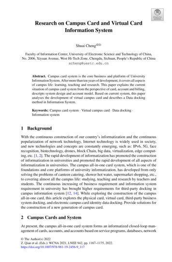
Front Panel (AP9640)Network10/100/1000ConsoleResetAP9640 Network Management Card 3ItemDescriptionUSB console portConnects the NMC to a local computer, via a micro-USB cable(APC part number 960-0603), to configure initial network settingsor access the command line interface (CLI).210/100/1000 Base-T connectorConnects the NMC to the Ethernet network.3Reset buttonRestarts the network management interface. NOTE: This does notaffect the output power of the device in which the NMC is installed.4Link-RX/TX (10/100/1000) LEDSee “Link-RX/TX (10/100/1000) LED”.5Status LEDSee “Status LED”.1UPS Network Management Card 3 User Guide6
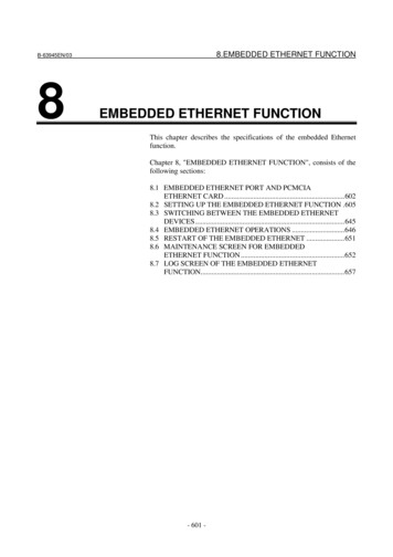
Front Panel (AP9641)NetworkUniversal I/OUSB10/100/10001Console2ResetAP9641 Network Management Card 3ItemDescriptionUSB portsSupport for UPS firmware updates and the optional APC USB Wi-FiDevice (AP9834). See “Update the UPS firmware from a USB drive(AP9641, AP9643 only)” and "Wi-Fi screen (AP9641 and AP9643only)".23Universal I/O portsConnect temperature sensors, temperature/humidity sensors, andrelay input/output accessory connectors to UIO port. The relay input/output accessory has two input contacts and one output relay.410/100/1000 Base-T connectorConnects the NMC to the Ethernet network.5Reset buttonRestarts the network management interface. NOTE: This does notaffect the output power of the device in which the NMC is installed.USB console portConnects the NMC to a local computer, via a micro-USB cable (APCpart number 960-0603), to configure initial network settings oraccess the command line interface (CLI).7Link-RX/TX (10/100/1000)LEDSee “Link-RX/TX (10/100/1000) LED”.8Status LEDAn LED (light-emitting diode) is a light source. See “Status LED”.167UPS Network Management Card 3 User Guide
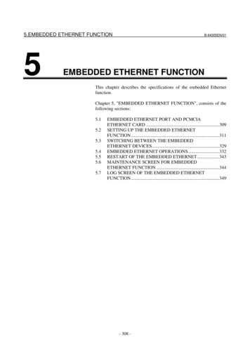
Front Panel (AP9643)NetworkModbusUSBUniversal I/OTXD0- 1 10/100/10001Console2Reset0- 1 ComRxDAP9643 Network Management Card 3ItemDescriptionUSB portsSupport for UPS firmware updates and the optional APC USB Wi-FiDevice (AP9834). See “Update the UPS firmware from a USB drive(AP9641, AP9643 only)” and "Wi-Fi screen (AP9641 and AP9643only)".Universal I/O portConnect temperature sensor, temperature/humidity sensor, or relayinput/output accessory connector to UIO port. The relay input/outputaccessory has two input contacts and one output relay.Modbus connectorConnects the NMC to a Building Management System (BMS). Twoterminal block plugs connectors are included (part number 7300532). To verify if your UPS supports Modbus, consult your UPSdocumentation.410/100/1000 Base-T connectorConnects the NMC to the Ethernet network.5Reset buttonRestarts the network management interface. NOTE: This does notaffect the output power of the device in which the NMC is installed.USB console portConnects the NMC to a local computer, via a micro-USB cable (APCpart number 960-0603), to configure initial network settings oraccess the command line interface (CLI).7Link-RX/TX (10/100/1000)LEDSee “Link-RX/TX (10/100/1000) LED”.8Status LEDAn LED (light-emitting diode) is a light source. See “Status LED”.1236UPS Network Management Card 3 User Guide8
LED DescriptionsStatus LEDThis LED (light-emitting diode) indicates the status of the NMC.ConditionDescriptionOffOne of the following situations exists: The NMC is not receiving input power. The NMC is not operating properly. It may need to be repaired or replaced.Contact Customer Support. See “APC World
User Guide UPS Network Management Card 3 AP9640, AP9641, AP9643 990-91148D-001 . Building Automation and Control Networks Protocol (BACnet) Simple Network Management Protocol versions 1, 2c and 3 . IPv6 can be used anywhere an IP address is entered on this interface. You can configure manually, automatically, or using DHCPv6, see .