Transcription
Remote I/OALLEN-BRADLEY Remote I/O Indicator Interfacefor 520, 720i , 820i and 920i Indicators Installation andProgramming Manual69950
ContentsAbout This Manual . 11.0Introduction. 12.0Installation . 22.1 Installing the Remote I/O Interface . . . . . . . . . . . . . . . . . . . . . . . . . . . . . . . . . . . . . . . . . . . . . . . . . . . 22.1.12.1.22.1.3Termination Resistance. . . . . . . . . . . . . . . . . . . . . . . . . . . . . . . . . . . . . . . . . . . . . . . . . . . . . . . . . . . . . 3A-B Network Connections . . . . . . . . . . . . . . . . . . . . . . . . . . . . . . . . . . . . . . . . . . . . . . . . . . . . . . . . . . 3LED Status Indicator . . . . . . . . . . . . . . . . . . . . . . . . . . . . . . . . . . . . . . . . . . . . . . . . . . . . . . . . . . . . . . . 32.2 DIP Switch Configuration . . . . . . . . . . . . . . . . . . . . . . . . . . . . . . . . . . . . . . . . . . . . . . . . . . . . . . . . . . 42.3 Decimal Point Handling . . . . . . . . . . . . . . . . . . . . . . . . . . . . . . . . . . . . . . . . . . . . . . . . . . . . . . . . . . . 53.0Discrete Transfer Commands . 63.1 Output Image Table Format . . . . . . . . . . . . . . . . . . . . . . . . . . . . . . . . . . . . . . . . . . . . . . . . . . . . . . . . 63.2 Input Image Table Format . . . . . . . . . . . . . . . . . . . . . . . . . . . . . . . . . . . . . . . . . . . . . . . . . . . . . . . . . 83.3 Discrete Command Descriptions . . . . . . . . . . . . . . . . . . . . . . . . . . . . . . . . . . . . . . . . . . . . . . . . . . . . 9Return Status and Current Weight. . . . . . . . . . . . . . . . . . . . . . . . . . . . . . . . . . . . . . . . . . . . . . . . . 9Display Channel . . . . . . . . . . . . . . . . . . . . . . . . . . . . . . . . . . . . . . . . . . . . . . . . . . . . . . . . . . . . . . 9Display Gross Weight . . . . . . . . . . . . . . . . . . . . . . . . . . . . . . . . . . . . . . . . . . . . . . . . . . . . . . . . . . 9Display Net Weight . . . . . . . . . . . . . . . . . . . . . . . . . . . . . . . . . . . . . . . . . . . . . . . . . . . . . . . . . . . . 9Display Piece Count . . . . . . . . . . . . . . . . . . . . . . . . . . . . . . . . . . . . . . . . . . . . . . . . . . . . . . . . . . . 9Gross/Net Key Press (toggle mode) . . . . . . . . . . . . . . . . . . . . . . . . . . . . . . . . . . . . . . . . . . . . . . . 9Zero . . . . . . . . . . . . . . . . . . . . . . . . . . . . . . . . . . . . . . . . . . . . . . . . . . . . . . . . . . . . . . . . . . . . . . . 9Display Tare . . . . . . . . . . . . . . . . . . . . . . . . . . . . . . . . . . . . . . . . . . . . . . . . . . . . . . . . . . . . . . . . . 9Enter Tare (integer) . . . . . . . . . . . . . . . . . . . . . . . . . . . . . . . . . . . . . . . . . . . . . . . . . . . . . . . . . . . . 9Acquire Tare (simulate tare key press) . . . . . . . . . . . . . . . . . . . . . . . . . . . . . . . . . . . . . . . . . . . . . . 9Clear Tare . . . . . . . . . . . . . . . . . . . . . . . . . . . . . . . . . . . . . . . . . . . . . . . . . . . . . . . . . . . . . . . . . . . 9Primary Units. . . . . . . . . . . . . . . . . . . . . . . . . . . . . . . . . . . . . . . . . . . . . . . . . . . . . . . . . . . . . . . . . 9Secondary Units . . . . . . . . . . . . . . . . . . . . . . . . . . . . . . . . . . . . . . . . . . . . . . . . . . . . . . . . . . . . . . 9Tertiary Units . . . . . . . . . . . . . . . . . . . . . . . . . . . . . . . . . . . . . . . . . . . . . . . . . . . . . . . . . . . . . . . . . 9Units Key Press (toggle units) . . . . . . . . . . . . . . . . . . . . . . . . . . . . . . . . . . . . . . . . . . . . . . . . . . . 10Print Request . . . . . . . . . . . . . . . . . . . . . . . . . . . . . . . . . . . . . . . . . . . . . . . . . . . . . . . . . . . . . . . 10Display Accumulator . . . . . . . . . . . . . . . . . . . . . . . . . . . . . . . . . . . . . . . . . . . . . . . . . . . . . . . . . . 10Clear Accumulator . . . . . . . . . . . . . . . . . . . . . . . . . . . . . . . . . . . . . . . . . . . . . . . . . . . . . . . . . . . 10Push Weight to Accumulator . . . . . . . . . . . . . . . . . . . . . . . . . . . . . . . . . . . . . . . . . . . . . . . . . . . . 10Return Gross as Integer . . . . . . . . . . . . . . . . . . . . . . . . . . . . . . . . . . . . . . . . . . . . . . . . . . . . . . . 10Return Net as Integer . . . . . . . . . . . . . . . . . . . . . . . . . . . . . . . . . . . . . . . . . . . . . . . . . . . . . . . . . 10Return Tare as Integer. . . . . . . . . . . . . . . . . . . . . . . . . . . . . . . . . . . . . . . . . . . . . . . . . . . . . . . . . 10Return Piece Count. . . . . . . . . . . . . . . . . . . . . . . . . . . . . . . . . . . . . . . . . . . . . . . . . . . . . . . . . . . 10Return Current Display as Integer . . . . . . . . . . . . . . . . . . . . . . . . . . . . . . . . . . . . . . . . . . . . . . . . 10Return Accumulator as Integer . . . . . . . . . . . . . . . . . . . . . . . . . . . . . . . . . . . . . . . . . . . . . . . . . . 10Return Rate of Change as Integer . . . . . . . . . . . . . . . . . . . . . . . . . . . . . . . . . . . . . . . . . . . . . . . . 10Return Peak as Integer . . . . . . . . . . . . . . . . . . . . . . . . . . . . . . . . . . . . . . . . . . . . . . . . . . . . . . . . 10Set Batching State . . . . . . . . . . . . . . . . . . . . . . . . . . . . . . . . . . . . . . . . . . . . . . . . . . . . . . . . . . . 10Batch Start . . . . . . . . . . . . . . . . . . . . . . . . . . . . . . . . . . . . . . . . . . . . . . . . . . . . . . . . . . . . . . . . . 10Technical training seminars are available through Rice Lake Weighing Systems.Course descriptions and dates can be viewed at www.ricelake.com/trainingor obtained by calling 715-234-9171 and asking for the training department. Rice Lake Weighing Systems. All rights reserved. Printed in the United States of America.Specifications subject to change without notice.Rice Lake Weighing Systems is an ISO 9001 registered company.March 2013
Batch Pause . . . . . . . . . . . . . . . . . . . . . . . . . . . . . . . . . . . . . . . . . . . . . . . . . . . . . . . . . . . . . . . . 11Batch Reset . . . . . . . . . . . . . . . . . . . . . . . . . . . . . . . . . . . . . . . . . . . . . . . . . . . . . . . . . . . . . . . . 11Batch Status . . . . . . . . . . . . . . . . . . . . . . . . . . . . . . . . . . . . . . . . . . . . . . . . . . . . . . . . . . . . . . . . 11Lock Front Panel of Indicator. . . . . . . . . . . . . . . . . . . . . . . . . . . . . . . . . . . . . . . . . . . . . . . . . . . . 11Unlock Front Panel of Indicator . . . . . . . . . . . . . . . . . . . . . . . . . . . . . . . . . . . . . . . . . . . . . . . . . . 11Set Digital Output ON . . . . . . . . . . . . . . . . . . . . . . . . . . . . . . . . . . . . . . . . . . . . . . . . . . . . . . . . . 11Set Digital Output OFF . . . . . . . . . . . . . . . . . . . . . . . . . . . . . . . . . . . . . . . . . . . . . . . . . . . . . . . . 11Read Digital I/O . . . . . . . . . . . . . . . . . . . . . . . . . . . . . . . . . . . . . . . . . . . . . . . . . . . . . . . . . . . . . . 11No Operation . . . . . . . . . . . . . . . . . . . . . . . . . . . . . . . . . . . . . . . . . . . . . . . . . . . . . . . . . . . . . . . 11Reset Indicator . . . . . . . . . . . . . . . . . . . . . . . . . . . . . . . . . . . . . . . . . . . . . . . . . . . . . . . . . . . . . . 11Set Register . . . . . . . . . . . . . . . . . . . . . . . . . . . . . . . . . . . . . . . . . . . . . . . . . . . . . . . . . . . . . . . . 11Get Register . . . . . . . . . . . . . . . . . . . . . . . . . . . . . . . . . . . . . . . . . . . . . . . . . . . . . . . . . . . . . . . . 114.0Block Transfer Commands. 124.1 Block Write Command Format. . . . . . . . . . . . . . . . . . . . . . . . . . . . . . . . . . . . . . . . . . . . . . . . . . . . . 134.2 Block Read Command Format . . . . . . . . . . . . . . . . . . . . . . . . . . . . . . . . . . . . . . . . . . . . . . . . . . . . 134.3 Block Transfer Command Descriptions . . . . . . . . . . . . . . . . . . . . . . . . . . . . . . . . . . . . . . . . . . . . . . 15Set Tare Value. . . . . . . . . . . . . . . . . . . . . . . . . . . . . . . . . . . . . . . . . . . . . . . . . . . . . . . . . . . . . . . 15Read Gross Weight . . . . . . . . . . . . . . . . . . . . . . . . . . . . . . . . . . . . . . . . . . . . . . . . . . . . . . . . . . . 15Read Net Weight. . . . . . . . . . . . . . . . . . . . . . . . . . . . . . . . . . . . . . . . . . . . . . . . . . . . . . . . . . . . . 15Read Tare Weight . . . . . . . . . . . . . . . . . . . . . . . . . . . . . . . . . . . . . . . . . . . . . . . . . . . . . . . . . . . . 15Read Piece Count . . . . . . . . . . . . . . . . . . . . . . . . . . . . . . . . . . . . . . . . . . . . . . . . . . . . . . . . . . . . 15Read Current Display . . . . . . . . . . . . . . . . . . . . . . . . . . . . . . . . . . . . . . . . . . . . . . . . . . . . . . . . . 15Read Accumulator . . . . . . . . . . . . . . . . . . . . . . . . . . . . . . . . . . . . . . . . . . . . . . . . . . . . . . . . . . . 15Read Rate of Change . . . . . . . . . . . . . . . . . . . . . . . . . . . . . . . . . . . . . . . . . . . . . . . . . . . . . . . . . 15Read Peak Value. . . . . . . . . . . . . . . . . . . . . . . . . . . . . . . . . . . . . . . . . . . . . . . . . . . . . . . . . . . . . 16Read Gross, Tare, Net . . . . . . . . . . . . . . . . . . . . . . . . . . . . . . . . . . . . . . . . . . . . . . . . . . . . . . . . 16Read Multiple Weights. . . . . . . . . . . . . . . . . . . . . . . . . . . . . . . . . . . . . . . . . . . . . . . . . . . . . . . . . 16Set Setpoint Value. . . . . . . . . . . . . . . . . . . . . . . . . . . . . . . . . . . . . . . . . . . . . . . . . . . . . . . . . . . . 16Set Setpoint Hysteresis . . . . . . . . . . . . . . . . . . . . . . . . . . . . . . . . . . . . . . . . . . . . . . . . . . . . . . . . 16Set Setpoint Bandwidth . . . . . . . . . . . . . . . . . . . . . . . . . . . . . . . . . . . . . . . . . . . . . . . . . . . . . . . 16Set Setpoint Preact . . . . . . . . . . . . . . . . . . . . . . . . . . . . . . . . . . . . . . . . . . . . . . . . . . . . . . . . . . . 16Set Single Setpoint, All Values. . . . . . . . . . . . . . . . . . . . . . . . . . . . . . . . . . . . . . . . . . . . . . . . . . . 17Read Setpoint Value . . . . . . . . . . . . . . . . . . . . . . . . . . . . . . . . . . . . . . . . . . . . . . . . . . . . . . . . . . 17Read Setpoint Hysteresis . . . . . . . . . . . . . . . . . . . . . . . . . . . . . . . . . . . . . . . . . . . . . . . . . . . . . . 17Read Setpoint Bandwidth . . . . . . . . . . . . . . . . . . . . . . . . . . . . . . . . . . . . . . . . . . . . . . . . . . . . . . 18Read Setpoint Preact . . . . . . . . . . . . . . . . . . . . . . . . . . . . . . . . . . . . . . . . . . . . . . . . . . . . . . . . . 18Read Single Setpoint, All Values . . . . . . . . . . . . . . . . . . . . . . . . . . . . . . . . . . . . . . . . . . . . . . . . . 18Set Multiple Setpoint Values . . . . . . . . . . . . . . . . . . . . . . . . . . . . . . . . . . . . . . . . . . . . . . . . . . . . 18Read Multiple Setpoint Values . . . . . . . . . . . . . . . . . . . . . . . . . . . . . . . . . . . . . . . . . . . . . . . . . . . 18. . . . . . . . . . . . . . . . . . . . . . . . . . . . . . . . . . . . . . . . . . . . . . . . . . . . . . . . . . . . . . . . . . . . . . . . . . 185.0Operation. 195.1 Test Program for Verifying Remote I/O Interface Operation . . . . . . . . . . . . . . . . . . . . . . . . . . . . . . . 195.2 PLC Program for Converting 20-bit Values to Floating Integers . . . . . . . . . . . . . . . . . . . . . . . . . . . . 215.3 Using Block Transfer to Set and Read Setpoint Values . . . . . . . . . . . . . . . . . . . . . . . . . . . . . . . . . . 226.0Remote I/O Interface Card Specifications. 24Remote I/O Interface Limited Warranty . 25Rice Lake continually offers web-based video training on a growing selectionof product-related topics at no cost. Visit www.ricelake.com/webinars.iiRemote I/O Installation and Programming Manual
About This ManualThis manual provides information needed to installand use the Rice Lake Weighing Systems Remote I/OInterface card. The Remote I/O Interface allows 520,720i , 820i , and 920i indicators to communicatewith PLC and SLC controllers using theAllen-Bradley Remote I/O network.1 See the 520,720i, 820i, or 920i Installation Manual for additionalinstallation information and detailed descriptions ofindicator functions.1.1.0Allen-Bradley , PLC , and SLC are trademarks ofAllen-Bradley Company, Inc., a Rockwell Internationalcompany.The Remote I/O Interface card is installed inside theindicator enclosure. Installation in NEMA 4Xstainless steel enclosures permits use in washdownenvironments.WarningSome procedures described in this manualrequire work inside the indicator enclosure.These procedures are to be performed byqualified service personnel only.Authorized distributors and their employeescan view or download this manual from theRice Lake Weighing Systems distributor siteat www.ricelake.com.IntroductionThe Remote I/O Interface returns weight and status information from the 520, 720i, 820i, or 920i indicator to thePLC controller. The Remote I/O Interface also provides the PLC programmer with limited control of indicatorfunctions. Indicator configuration and calibration cannot be performed through the Remote I/O Interface.The Remote I/O Interface behaves as a node adapter device to the master PLC, appearing as a quarter rack of I/O.The PLC controller and Remote I/O Interface communicate using a quarter rack of data slots (4 slots with 8 bitsof input, 8 bits of output per slot). Each pair of slots corresponds to a “module group”, one input and one outputword. The Remote I/O Interface contains two module groups and therefore communicates two words of data.The PLC controller sends commands to the indicator through the Remote I/O Interface by writing the commandsto the output image table, and reads returned weight and status data from the input image table. These actions arereferred to as discrete transfers. See Section 3.0 for information about using discrete transfer commands.Block transfers are accomplished by sending a block write command followed by a block read command.Separate data files are set up for block commands. The length of these files depends on the length of the databeing read or written. See Section 4.0 for information about using block transfer commands.Introduction1
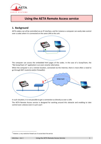
2.0InstallationThis section describes the procedures used to installthe Remote I/O interface card into the 520, 720i, 820i,and 920i indicators; connect communications cables;select the termination resistance; and set theconfiguration DIP switches for the Remote I/Ointerface.2.1.1612810181413To r q u e b a c k p l a t e s c r e w sto 15 in-lb (1.7 N-m)Installing the Remote I/O InterfaceUse the following procedure to install the Remote I/OInterface card into 520, 720i, 820i, and 920i indicators.1. Disconnect indicator from power source.5632Disconnect power before removing indicatorbackplate. The 520, 720i, 820i, and 920ihave no on/off switch. Before opening theunit, ensure the power cord is disconnectedfrom the power outlet.14111511. Reconnect power to the indicator. Theindicator automatically recognizes allinstalled option cards when the unit ispowered on. No hardware-specificconfiguration is required to identify thenewly-installed Remote I/O card to thesystem.CPU board connectionJ1P1TP1TP34567SW281567SW18123TP243. Carefully align the option card connector withthe option card slot on the indicator CPUboard (or 920i expansion board). Press downto seat the option card in the CPU boardconnector.4. Use the screws provided in the option kit tosecure the other end of the option card to thethreaded standoffs on the CPU board.5. Set termination resistance (jumper JMP4) asdescribed in Section 2.1.1 on page 3.6. Wire the card to the network as described inSection 2.1.2 on page 3.7. Set DIP switches as described in Section 2.2on page 4.8. Use cable ties to secure loose cables inside theenclosure.9. For indicator models that include a backplate,position the backplate over the enclosure andreinstall the backplate screws. For the 820iand 920i desktop and universal models, usethe torque pattern shown in Figure 2-1 toprevent distorting the backplate gasket.Torque screws to 15 in-lb (1.7 N-m).10. Ensure no excess cable is left inside theenclosure and tighten cord grips.73Use a wrist strap to ground yourself andprotect components from electrostaticdischarge (ESD) when working inside theindicator enclosure.922. Open indicator enclosure. For indicatormodels with backplates, place indicatorface-down on an antistatic work mat andremove screws that hold the backplate to theenclosure body.17Figure 2-1. 820i and 920i Enclosure Backplate.1WarningSTATUS LED1150Ω82ΩJ21, 4 BLUE2, 5 SHIELD3, 6 CLEARJMP41Allen-Bradley NetworkconnectionsFigure 2-2. Remote I/O Interface Card2Remote I/O Installation and Programming Manual
2.1.1Termination Resistance2.1.2If the Remote I/O Interface is the last, or only, deviceattached to the PLC, the interface must provide atermination resistance. Use Table 2-1 to determine theappropriate termination resistance value and JMP4jumper position for the network. If the Remote I/OInterface is not the last device in a chain, position thejumper on one pin only. Resistance values for thejumper positions are marked on the Remote I/OInterface card.A-B Network ConnectionsConnections to the Allen-Bradley network are made atconnector J2 on the Remote I/O Interface card (seeFigure 2-2). Connectors 4–6 are tied to connectors1–3 to allow daisy-chaining through the Remote I/OInterface.Feed Allen-Bradley network cable through cord grip.Allow enough cable for routing along inside ofenclosure to J2 connector on the Remote I/O Interfacecard. Connect Allen-Bradley network cables intoconnector J2 on the Remote I/O Interface card, thenuse cable ties to secure network cables to the cable tiemounts.Network DataRateMaximumCable LengthMaximumNodesJMP4TerminationResistance16150 2.1.382 A single LED on the Remote I/O card provides statusinformation for troubleshooting (see Figure 2-2).Table 2-2 summarizes the function of the LED.57.6 Kbps10 000 ft115.2 Kbps5000 ft230.4 Kbps2500 ft32Table 2-1. JMP4 Jumper Positions and TerminationResistance ValuesLED Status IndicatorLEDOFFPulsing(2Hz)ONFunctionNot initialized or not receiving valid framesCommunications established with Command1’s or timeoutValid communications established withCommand 2’sTable 2-2. Remote I/O Interface Status LEDInstallation3
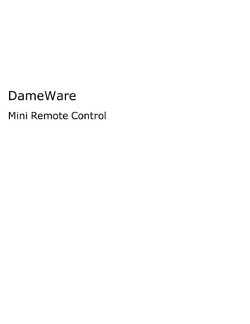
2.2DIP Switch Configuration233456ReservedBlock Transfer1ReservedRack AddressLSBRack SizeLink AddressStartingQuarterLast RackNetworkData RateTwo banks of DIP switches, SW1 and SW2, are used to configure the Remote I/O Interface for communicationwith the indicator and the network. Figure 2-3 shows the switch assignments for SW1 and SW2.MSB4567812OPENOPENSW1SW278Figure 2-3. SW1 and SW2 DIP Switch Assignments.Starting QuarterSwitches SW1-1 and SW1-2 set the starting quarter(or group number) used by the Remote I/O Interface.Use Table 2-3 to select the correct switch settings.SW1 Switch ED2nd2OPENCLOSED3rd4CLOSEDOPEN4th6OPENOPENTable 2-3. Starting QuarterSW2 Switch SettingsRemote I/O Data Rate1257.6 KbpsCLOSEDCLOSED115.2 KbpsOPENCLOSED230.4 KbpsCLOSEDOPENOPENOPENTable 2-4. Network Data RateLast RackSet SW2-3 OPEN if the Remote I/O Interface linkaddress includes the highest module group in this rackaddress.Rack AddressRack SizeSwitches SW1-3 through SW1-8 are used to set therack address of the Remote I/O Interface. Use Tableon page 5 to select the correct switch settings for therack address. Note that setting a switch OPEN acts as aAt this time only a quarter rack size is supported. Thisoption has been included for possible future expansionto include half rack support. Switch 2-4 is ignored.logical “1” and that SW1-3 represents the least significant bit(LSB) of the rack address.Network Data RateSW2-1 and SW2-2 set the data rate of theAllen-Bradley network. Use Table 2-4 to select thecorrect switch settings for the network.4Remote I/O Installation and Programming ManualBlock TransferSet SW2-6 CLOSED to enable or OPEN to disableblock transfer to the Remote I/O Interface. Setting thisswitch OPEN causes the Remote I/O Interface toignore unsolicited block transfer requests from thePLC.
Rack AddressSW1 Switch Settings (LSB— ack Address8DecimalOctal32403341OPENCLOSED CLOSED CLOSED CLOSED3442CLOSEDOPENCLOSED CLOSED CLOSEDOPENCLOSED CLOSED CLOSED CLOSED3543OPENOPENCLOSED CLOSED CLOSEDOPENCLOSED CLOSED CLOSED3644OPENCLOSED CLOSEDOPENCLOSED CLOSED CLOSED3745OPENCLOSEDOPENCLOSED CLOSEDOPENOPENCLOSED CLOSED CLOSED3846CLOSEDOPENOPENCLOSED CLOSEDOPENOPENCLOSED CLOSED CLOSED3947OPENOPENOPENCLOSED CLOSEDOPENCLOSED CLOSED CLOSED CLOSED CLOSED CLOSEDCLOSED CLOSED CLOSED CLOSED CLOSEDCLOSED CLOSEDSW1 Switch Settings (LSB— MSB)CLOSED CLOSED CLOSED34CLOSED CLOSEDCLOSED CLOSED4050CLOSED CLOSED4151OPENCLOSEDOPENCLOSED CLOSED4252CLOSEDOPENCLOSEDOPENCLOSED CLOSED4353OPENOPENOPENOPENCLOSED CLOSED4454OPENOPENCLOSED CLOSED4555OPENCLOSEDOPENOPENOPENCLOSED CLOSED4656CLOSEDOPENOPENOPENCLOSED CLOSED4757OPENCLOSED CLOSED CLOSED CLOSED7CLOSED CLOSED CLOSED CLOSEDOPENCLOSED CLOSED6CLOSED CLOSED CLOSED CLOSED CLOSEDOPENCLOSED CLOSED5CLOSED CLOSED PENCLOSEDOPENOPENOPENOPENOPENCLOSED CLOSEDCLOSED CLOSEDOPENCLOSED4860OPENCLOSED4961OPENCLOSED CLOSEDOPENCLOSED5062CLOSEDOPENCLOSED CLOSEDOPENOPENCLOSED CLOSEDOPENCLOSED5163OPENOPENCLOSED ENOPENCLOSED CLOSED CLOSEDCLOSED CLOSEDCLOSED CLOSED CLOSEDCLOSED CLOSEDCLOSED CLOSEDCLOSED CLOSED CLOSED CLOSEDCLOSED CLOSED CLOSEDCLOSED CLOSEDCLOSED CLOSED CLOSEDCLOSED CLOSEDCLOSED CLOSEDTable 2-5. SW1 Switch Settings for Remote I/O Interface Rack Address2.3Decimal Point HandlingDiscrete TransferDiscrete transfer commands return no decimal point information to the PLC. For example, a value of 750.1displayed on the indicator is returned to the PLC as 7501.Block TransferBlock transfer commands support decimal point information with no special handling.Installation5
3.0Discrete Transfer CommandsDiscrete commands are used by the PLC to send and receive data from the Remote I/O Interface. The PLCcontroller and Remote I/O Interface share a quarter rack of slot space, resulting in two 16-bit words for the outputimage table (used to write commands to the indicator) and two 16-bit words for the input image table (used toread data from the indicator).NOTE: Data returned by discrete transfer commands is not valid when the indicator is in setup mode.3.1Output Image Table FormatTo perform a discrete command, the PLC places two 16-bit words in the PLC output image table, which is sentby the scanner to the node adapter of the Remote I/O Interface. The Remote I/O Interface provides the contentsof the output image table to the indicator for command processing.The format of the output image table is shown in Table 3-1.Bit1514131211109876543210Word ord able 3-1. Output Image Table FormatParameter valuewhere:v00–v15p00–p07c00–c07To allow communication with a multi-scale indicator,the scale number is sent in the upper byte of word 1. Avalue of 0 represents the current scale. Certaincommands require a parameter other than a scalenumber. These commands are noted in the table asrequiring a slot number or other selection parameter.16-bit unsigned integer valueParameter valueCommand numberThese fields are described below:ValueWord 0 of the output image table is used to pass valuedata on certain commands. This field should be usedonly when block transfer is disabled. For example, toenter a tare value, use word 0 to specify the tare value;the Enter Tare command number (12) is specified inbits 00 through 07 of word 1.Values entered in this field are treated as unsignedintegers. Possible values range from 0 to 65535.Command NumberThe number representing the indicator command issent in the lower byte of word 1. Table 3-2 lists theremote commands that can be specified for 520 and920i indicators on discrete write commands.NOTE: A lockout feature that looks for any change in theimage table data is incorporated into the indicator receivemechanism to prevent inundation by the same command.Repeated commands must be separated by any other validcommand/parameter/value combination.DecimalHexBinaryCommand00x000000 0000Return Status and Weight10x010000 0001Display Channel20x020000 0010Display Gross Weight30x030000 0011Display Net Weight40x040000 0100Display Piece Count90x090000 1001Gross/Net key press (toggle mode)100x0A0000 1010Zero110x0B0000 1011Display Tare120x0C0000 1100Enter Tare (integer)130x0D0000 1101Acquire TareTable 3-2. 520 /720i/ 820i / 920i Remote Commands6Remote I/O Installation and Programming Manual
DecimalHexBinaryCommand140x0E0000 1110Clear Tare160x100001 0000Primary Units170x110001 0001Secondary Units180x120001 0010Tertiary Units190x130001 0011Units key press (toggle units)200x140001 0100Print Request210x150001 0101Display Accumulator220x160001 0110Clear Accumulator230x170001 0111Push Weight to Accumulator320x200010 0000Return Gross (integer)330x210010 0001Return Net (integer)340x220010 0010Return Tare (integer)350x230010 0011Return Piece Count370x250010 0101Return Current Display (integer)380x260010 0110Return Accumulator (integer)390x270010 0111Return Rate of Change (integer)400x280010 1000Return Peak (integer)950x5F0101 1111Set Batching State960x600110 0000Batch Start970x610110 0001Batch Pause980x620110 0010Batch Reset990x630110 0011Batch Status1120x700110 0100Lock Indicator Front Panel1130x710110 0101Unlock Indicator Front Panel1140x720110 0110Set Digital Input ON1150x730110 0111Set Digital Input OFF1160x740110 1000Read Digital Input Status2530xFD1111 1101No operation2540xFE1111 1110Reset Indicator3680x17010111 0000Set Register4020x19211001 0010Get RegisterTable 3-2. 520 /720i/ 820i / 920i Remote Commands (Continued)Discrete Transfer Commands7
3.2Input Image Table FormatIn response to a discrete command, the Remote I/O Interface interface returns data and status information acrossthe network as two 16-bit words. This information is read from the input image table by the PLC. The format ofthe input image table is shown in Table 3-3:Bit1514131211109876543210Word ord able 3-3. Input Image Table Formatwhere:v00–v19s00–s1120-bit unsigned integerStatus dataValueWeight data is returned to the PLC using word 0 andbits 0 to 3 from word 1 of the input image table. ThePLC can use just word 0 to read data in a 16-bitformat, allowing unsigned values from 0 to 65,535 tobe returned from the indicator. If larger numbers orgreater precision is required, the PLC can piecetogether the additional four bits from word 1, resultingin a 20-bit unsigned value. This format allows theindicator to return values up to 1,048,575. Polarity isreturned with status data. The weight data returned isthe displayed weight after the command is executedunless the command specifies otherwise.Indicator Status DataWord 1BitStatusBitValue 0Value 104s00Positive weightNegative weight05s0106s0207s0308s04GrossNet09s05No tareTare acquired10s06Primary unitsSecondary/ otherunits11s07StandstillIn motionLower three bits of scale numberStatus DataIndicator status data is returned in bits 4–15 of word 1.Status data is listed in Table 3-4. Batch commandsreturn batch status in place of bits 8–15 as listed inTable 3-5.12s08Weight invalid /Over-rangeWeight OK13s09Not zeroCenter of zeroChannel Bits14s10Tare not enteredTare entered15s11ErrorNo errorBits s01–s03 of the indicator status data (Table 3-4)are used to represent the lower three bits of the scalechannel number. For example, if a value of ‘0
Feed Allen-Bradley network cable through cord grip. Allow enough cable for routing along inside of enclosure to J2 connector on the Remote I/O Interface card. Connect Allen-Bradley network cables into connector J2 on the Remote I/O Interface card, then use cable ties to secure network cables to the cable tie mounts.