Transcription
IMPEDANCE CALCULATIONINTRODUCTIONIn modern devices signals are operating at higherfrequencies, rising and falling edges are reduced (1 nsBENEFITS OF THE ALTIUM DESIGNERIMPEDANCE CALCULATOR Supports different line structures:or less), and the frequency is increased (to tens of GHz). Microstrip - the outer layersThis requires the use of printed circuit boards (PCB) with Stripline - is constructed with a flat conductor sus-controlled impedance in order to prevent distortion of thepended between two ground planes, where thesignal when it is transmitted over the conductors.conductor and ground planes are separated by adielectric.A conductor on a PCB is no longer just a track linking the contact pads and vias, but a transmission line that has toEmbedded Microstrip - a flat conductor suspendedover a ground plane with a dielectric between it andtransmit a signal with low-loss of shape, amplitude andanother dielectric material above the conductorvelocity. Asymmetric Stripline - is most commonly found in aWhen designing a PCB, the developer must determinepcb where the distance from trace to planes is not thewhich layers contain impedance-controlled conductorssame distance above and below (or differential pairs) and which layers contain ground andpower reference layers. The developer’s task is to performpreliminary calculations of the PCB structure and design ittaking into account the calculated values of the conductorwidth in the specified layers.Modern CAD for PCB design should support differenttransmission line structures and consider as many Uses a material library Provides transmission line calculation for several impedance values (including single layer) Automatic impedance calculation Visual presentation of complete information abouttransmission line, including layer structure with parameters and line constructions Accounts for side etching ofconductor Considers mask thickness above the conductor andabove the board Enables Selection of model and roughness parameters Performs Delay Calculation Provides Inductance calculation Provides Capacitance calculation Available for FREE as part of Altium Designer 20 andbeyondparameters that can affect the calculation of impedanceas possible. The impedance calculator must use the mostaccurate formulas for calculation.Controlled impedance of PCBs raises the process of design,material selection, structure and production of PCBs to a newlevel.www.altium.comCoplanar - lines that lie on the same plane
IMPEDANCE CALCULATIONEXAMPLE OF IMPEDANCE CALCULATIONWhen designing a board with controlled impedance, engineers need to minimize manufacturing costs. Therefore, at theinitial stage, engineers tend to focus on certain parameters including conductor thickness and gap. Then, using the selectedparameters, the developer attempts to select the appropriate materials and PCB stack. There is an example below showinghow this can be done using the Altium Designer Layer Stack Manager and its impedance calculation capability. It is worthnoting that the opposite situation is possible in projects when the PCB stack is a constant and the user must determine thewidth of the conductor and the gap.Example:It is necessary to design Edge-Coupled Microstrip on the outer layers of the 6-layer board.Input parameters:Line width 0.2 mmGap between the lines 0.2 mm100 Ohm impedance, tolerance not more than 5%.It is necessary to select the stack materials.1.Load the PCB stack of 6 layers into the Layer Stack Manager.www.altium.com
IMPEDANCE CALCULATION2.Display the Properties panel. Using the Panels at the bottom-left of the workspace, select the Properties panel. This panelshould always be open when working in the Layer Stack Manager.3.Select the Impedance tab in the Layer Stack Manager.4.Add the Impedance Profile by clicking the button.5.In the Properties panel in the Impedance Profile section, select the Differential type, Set the Target Impedance value to100 and Target Tolerance field to 5%.www.altium.com
IMPEDANCE CALCULATION6.Select the layer where the transmission line will be located. Specify 1 layer (Top Layer) in the impedance profile, to highlight all layers in the stack-up that participate in the calculation of this transmission line (display the structure and parameters of this line). In the impedance profile in the Bottom Ref column - select the nearest reference layer 2 - Int1 (GND).In the Properties panel in the Transmission Line section, the selected line construction is displayed.7.Disable Layers 3-Int2 (Sign) and 4-Int3 (Sign) in the profile, as the task is to count only microstrip transmission line.8.Set the checkbox for the use of the Surface finish in the Properties panel, which requires a Surface finish layer in the stack-up.9.In the Properties panel - change the line width W1 0.2 mm, W2 0.18 mm. Etching (W2) - this setting depends on the technological specifics of the PCB fabricator.10. Change the thickness of the mask over the board C1 0.03 mm, over the conductor C2 0.025 mm. This parameter dependson the material and technological specifics of the PCB fabricator. As a rule, the mask thickness above the dielectric and abovethe conductor are different.11. Set the gap between the differential pairs G 0.2 mm.www.altium.com
IMPEDANCE CALCULATION12. Select another material for the outer layer copper library by ½ oz (Thickness 0.018mm). Since the copper thicknessaffects the impedance, and total thickness of the outer layers of the metal layer will be added to the copper plus thesurface finish, it is possible to change the copper thickness to adapt the calculation to a given impedance. If such a material is available from the fabricator.13. Change the prepreg for the Dielectric 2 layer to PP-014 (Thickness 0.107 and Dk 4.2). Also note that the impedancecalculation is more influenced by the dielectric thickness, the width of the conductor and, to a lesser extent, the Dk parameter. In this example, it is necessary to raise the impedance value, but we cannot change the width of the conductor.The simplest solution is to use a thicker dielectric. Of course, the engineer has to be in regular contact with the fabricator to assure that the material is available and that this solution is technologically feasible.www.altium.com
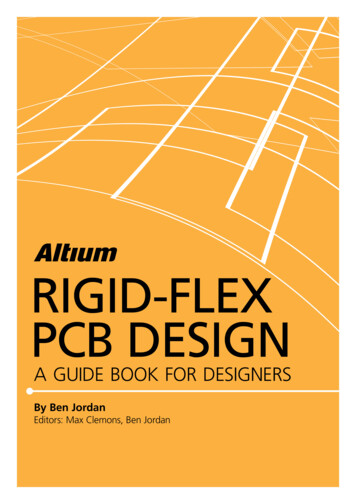
IMPEDANCE CALCULATION14. In the Properties panel, in the Other section - specify the model and roughness parameters. Use the following as anexample of the copper roughness setting Model Type - Huray-Bracken, SR 0.2, RF 2. This parameter is set for highspeed transmission lines.15. View of the Impedance tab after all of the calculations have been changed01 - Contents Transmission Line03 - Structure Transmission Line05 - Calculated p arameters02 - Reference layers04 - Advanced parameters for input06 - Roughnesswww.altium.com
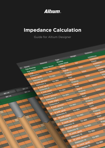
IMPEDANCE CALCULATION16. Final impedance calculation:Use caseDescriptionZdiff (calculated)Target Impedance value:Zdiff 100OhmBasic use caseStackup parameters:H1 0.107 mm, Dk1 4.2,H2 0.071 mm, Dk2 4.1,T 0.38 mm, W1 0.2 mm. W2 0.18 mm,Trace Gap (G) 0.2 mm, Surface Finish 0.02mmZdiff 100.8 OhmSolder Mask :C1 0.03 mm, C2 0.025 mm, CDk 4Roughness:Model Type-Huray-Bracken, SR 0.2µm, RF 2C1 C2 0.03 mm, other parameters without changes frombasic caseZdiff 100.7 OhmIf Model Type Flat Conductors and SR 0.1µm, otherparameters without changes from basic caseZdiff 100.6 OhmWithout etchingIf W2 0.2 mm, other parameters without changes frombasic caseZdiff 98.6 OhmWithout surface finishSurface Finish checkbox disabled, other parameterswithout changes from basic caseZdiff 105.1 OhmWithout solder maskdifferentiationWithout the roughnessof copperwww.altium.com
IMPEDANCE CALCULATIONCOMPARISON OF BASIC CALCULATORS BY FUNCTIONALITYHigh End CalculatorEmbedded in CADPCB CalculatorMaterials Library--3Interrelation of stack-up andtransmission line-4Coplanar transmission line Feature name1Basic transmission lines (Microstripand rics with different thicknesses and5-different Dk6Accounting for side etching of conductor-Accounting of the mask thickness above7-the conductor and above the board-Selection of model and roughness8parameters9Cost10DeliveryFreePart of PCBDesign tool-(no model selection)(no model selection) FreeSeparate softwareExtra optionWeb pageCOMPARISON OF BASIC CALCULATORS IN CALCULATION ACCURACYInput data: Model and roughness values for copper are not defined. The default model used in AD is Flat Conductors(SR 0.1µm, RF 2). T - Trace Thickness with Surface Finish (mm) H - Substrate Height (mm), 1,2,3. dielectric numerationfrom bottom to top in the transmission line Dk - dielectric constant, 1,2,3. numbering of corresponding dielectrics W1 - base trace width (mm)Examplewww.altium.com W2 - etched trace width (mm) C1 - mask thickness above the board (mm) C2 - mask thickness above the conductor (mm) G - Gap between lines in diff. pair (mm) S - clearance to the reference layer for coplanarlines (mm)
IMPEDANCE CALCULATION Transmission line type and source dataAltiumDesignerHigh EndCalcEmbeddedin CAD PCB CalcOnlineCalcImpedance valueMicrostrip Single (Target Impedance 50 Ohm)T 0.055, H1 0.1,Dk1 4.6, W1 0.16,W2 0.14150.3449.3549.750.0549.5249С1 С2 0.0349.52without W2Microstrip with Soldermask (Target Impedance 50 Ohm)T 0.055, H1 0.1,Dk1 4.5, W1 0.14,W2 0.12, С1 0.03,С2 0.02, CDk 4248.46without W2,C1,СDkMicrostrip with Soldermask and few dielectrics(Target Impedance 50 Ohm)T 0.055, H1 0.08,Dk1 4.2, H2 0.12,Dk2 4.4, H3 0.1,Dk3 4.6, W1 0.5,W2 0.48, С1 0.03,С2 0.02, CDk 4350.07notsupported49.9С1 С2 0.03notsupportedEmbedded Microstrip (Target Impedance 50 Ohm)T 0.035, H1 0.2,Dk1 4.2, H2 0.2,Dk2 4.2, W1 0.3,W2 0.28449.8549.7449.450.1150.804948.68without W2Symmetric Stripline (Target Impedance 50 Ohm)T 0.035, H1 0.2,Dk1 4.4, H2 0.2,Dk2 4.4, W1 0.15,W2 0.13547.89without W2Asymmetric Stripline (Target Impedance 50 Ohm)6www.altium.comT 0.035, H1 0.18,Dk1 4, H2 0.16,Dk2 4.2, H3 0.14,Dk3 4.4, H4 0.12,Dk3 4.6, W1 0.13,W2 0.1150.40notsupported49.4notsupported
IMPEDANCE CALCULATION Transmission line type and source dataAltiumDesignerHigh EndCalcEmbeddedin CAD PCB CalcOnlineCalcImpedance valueEdge-Coupled Microstrip with soldermask(Target Impedance 100 Ohm)T 0.055, H1 0.2,Dk1 4, W1 0.14,W2 0.12, С1 0.03,С2 0.02, CDk 4,G 0.13799.9999.5899.5105.74С1 С2 without W2,C1,0.03СDknotsupportednotsupportedMicrostrip Coplanar (Target Impedance 50 Ohm)T 0.055, H1 0.17,Dk1 4.5, W1 0.14,W2 0.12, С1 0.03,С2 0.02, CDk 4,S 0.1850.0750.2499.90100.2Edge-Coupled Microstrip Coplanar(Target Impedance 100 Om)T 0.055, H1 0.5,Dk1 4.3, W1 0.16,W2 0.14, С1 0.03,С2 0.02, CDk 4,S 0.1, G 0.29notnotsupportedsupportedCONCLUSIONS To design high-speed and high-frequency devices modernCAD must support different transmission line structures.Unlike other programs, Altium Designer supports most ofthem. Parameters such as mask height, side etching of theconductor and roughness must be taken into account tocalculate the impedance accurately. This is especially truefor high-speed devices. Altium Designer allows you to dothis to the fullest extent. The transmission line impedance is calculated as a part ofthe entire stack-up, which allows the engineer to see thewhole picture. The wave impedance depends largely on the material.Parameters such as resin content, mesh density influencedielectric permeability and therefore impedance. The useof the material library allows you to select the necessarymaterial quickly thereby reducing the time to design thestructure of the transmission line structure design. When designing equipment with controlled impedance,calculations are used to predict the capacitance and inductance on which the impedance depends. The formulasused in Altium Designer are based on empirical dependencies and are unique for different configurations.Impedances in Altium Designer are simulated with Simbeor software.www.altium.com
W1 - base trace width (mm) W2 - etched trace width (mm) C1 - mask thickness above the board (mm) C2 - mask thickness above the conductor (mm) G - Gap between lines in diff. pair (mm) S - clearance to the reference layer for coplanar lines (mm) Feature name Altium Designer High End Calculator Embedded in CAD