Transcription
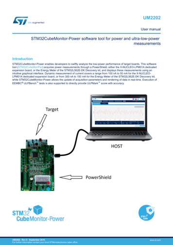
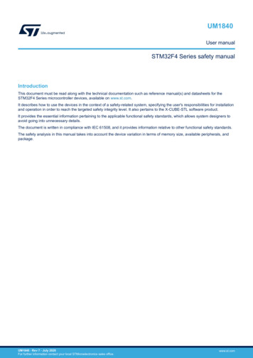
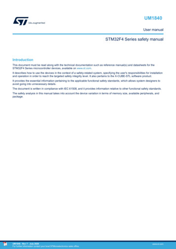
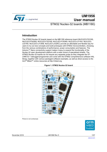
UM2591User manualSTM32G0 Nucleo-32 board (MB1455)IntroductionThe STM32G0 Nucleo-32 board based on the MB1455 reference board (NUCLEO-G031K8) provides an affordable and flexibleway for users to try out new concepts and build prototypes by choosing from the various combinations of performance andpower consumption features, provided by the STM32G0 microcontroller.The Arduino Nano V3 connectivity support allows the easy expansion of the functionality of the STM32 Nucleo opendevelopment platform with a wide choice of specialized shields.The STM32G0 Nucleo-32 board does not require any separate probe as it integrates the ST-LINK/V2-1 debugger/programmer.The STM32G0 Nucleo-32 board comes with the STM32 comprehensive free software libraries and examples available with theSTM32CubeG0 MCU Package.Figure 1. NUCLEO-G031K8 top viewFigure 2. NUCLEO-G031K8 bottom viewPictures are not contractual.UM2591 - Rev 1 - June 2019For further information contact your local STMicroelectronics sales office.www.st.com
UM2591Features1Features STM32G031K8T6U microcontroller (Arm Cortex -M0 at 64 MHz) in LQFP32 package, featuring64 Kbytes of Flash memory and 8 Kbytes of SRAM1 user LED1 RESET or user push-buttonBoard connectors: –Arduino Nano V3 expansion connector–USB with Micro-BFlexible power-supply options: ST-LINK USB VBUS or external sources Note:UM2591 - Rev 1On-board ST-LINK/V2-1 debugger/programmer with USB re-enumeration capability: mass storage, VirtualCOM port, and debug portComprehensive free software libraries and examples available with the STM32CubeG0 MCU PackageSupport of a wide choice of Integrated Development Environments (IDEs) including IAR , Keil , GCCbased IDEsArm is a registered trademark of Arm Limited (or its subsidiaries) in the US and/or elsewhere.page 2/26
UM2591Ordering information2Ordering informationTo order the STM32G0 Nucleo-32 board, refer to Table 1. Additional information is available from the datasheetand reference manual of the target STM32.Table 1. List of available products2.1Order codeReference boardTarget STM32NUCLEO-G031K8MB1455STM32G031K8T6UProduct markingEvaluation tools marked as “ES” or “E” are not yet qualified and therefore not ready to be used as referencedesign or in production. Any consequences deriving from such usage will not be at ST charge. In no event, ST willbe liable for any customer usage of these engineering sample tools as reference design or in production.“E” or “ES” marking examples of location: On the targeted STM32 that is soldered on the board (for illustration of STM32 marking, refer to the STM32datasheet “Package information” paragraph at the www.st.com website). Next to the evaluation tool ordering part number that is stuck or silk-screen printed on the board.This board features a specific STM32 device version, which allows the operation of any bundled commercialstack/library available. This STM32 device shows a "U" marking option at the end of the standard part numberand is not available for sales.In order to use the same commercial stack in his application, a developer may need to purchase a part numberspecific to this stack/library. The price of those part numbers includes the stack/library royalties.2.2Products and codificationThe meaning of the codification is explained in Table 2.Table 2. Codification explanationNUCLEO-XXYYKTDescriptionExample: NUCLEO-G031K8XXMCU series in STM32 Arm Cortex MCUsSTM32G0 SeriesYYMCU product line in the seriesSTM32G031KSTM32 package pin count32 pinsTSTM32 Flash memory size: 8 for 64 Kbytes64 KbytesThe order code is mentioned on a sticker placed on the top side of the board.UM2591 - Rev 1page 3/26
UM2591Development environment3Development environment3.1System requirements Windows OS (7, 8 and 10), Linux 64-bit, or macOS USB Type-A to Micro-B cableNote:macOS is a trademark of Apple Inc. registered in the U.S. and other countries.3.2Development toolchains Keil free MDK-ARM (see note) IAR EWARM (see note)GCC-based IDEsNote:On Windows only.3.3Demonstration softwareThe demonstration software, included in the STM32Cube MCU Package corresponding to the on-boardmicrocontroller, is preloaded in the STM32 Flash memory for easy demonstration of the device peripherals instandalone mode. The latest versions of the demonstration source code and associated documentation can bedownloaded from www.st.com.UM2591 - Rev 1page 4/26
UM2591Conventions4ConventionsTable 3 provides the conventions used for the ON and OFF settings in the present document.Table 3. ON/OFF conventionUM2591 - Rev 1ConventionDefinitionJumper JPx ONJumper fittedJumper JPx OFFJumper not fittedJumper JPx [1-2]Jumper should be fitted between Pin 1 and Pin 2Solder bridge SBx ONSBx connections closed by 0 Ω resistorSolder bridge SBx OFFSBx connections left openResistor Rx ONResistor solderedResistor Rx OFFResistor not solderedpage 5/26
UM2591Quick start5Quick startThe STM32G0 Nucleo-32 board is a low-cost and easy-to-use development kit, used to evaluate and start adevelopment quickly with an STM32G0 Series microcontroller in LFQFP 32-pin package. Before installing andusing the product, accept the Evaluation Product License Agreement from the www.st.com/epla webpage. Formore information on the STM32G0 Nucleo-32 and for demonstration software, visit the www.st.com/stm32nucleowebpage.5.1Getting startedFollow the sequence below to configure the STM32G0 Nucleo-32 board and launch the demonstration application(refer to Figure 4 for component location):1.Check the jumper position on the board (refer to Table 4)2.For the correct identification of the device interfaces from the host PC and before connecting the board,install the ST-LINK/V2-1 USB driver available on the www.st.com website3.To power the board, connect the STM32G0 Nucleo-32 board to a PC with a USB cable (Type-A to Micro-B)through the USB connector CN1 of the board4.Then, red LED LD1 (COM) and green LED LD2 (5V PWR) light up, green LED LD3 blinks5.Remove the jumper placed between D2 (CN3 pin 5) and GND (CN3 pin 4)6.Observe how the blinking of the green LED LD3 changes, when the jumper is in place or removed7.Download the demonstration software and several software examples that help to use the STM32 Nucleofeatures. These are available on the NUCLEO-G031K8 webpage8.Develop your own application using the available examplesTable 4. Jumper mment(1)For STM32G0 current measurement1. Default jumper state is shown in bold.UM2591 - Rev 1page 6/26
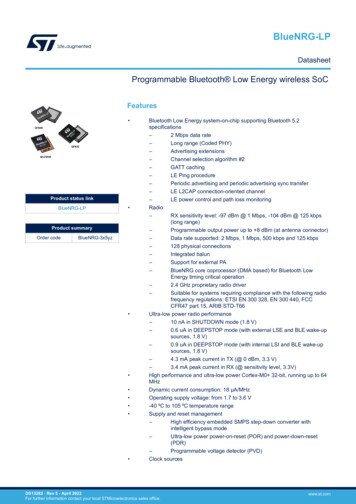
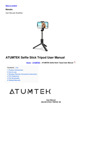
UM2591Hardware layout and configuration6Hardware layout and configurationThe STM32G0 Nucleo-32 board is designed around an STM32G031 microcontroller in an LFQFP 32-pinpackage. Figure 3 shows the connections between the STM32 and its peripherals (ST-LINK/V2-1, push-button,LEDs, USB, and Arduino Nano). Figure 4. Top layout and Figure 5. Bottom layout show the location of thesefeatures on the STM32G0 Nucleo-32 board. The mechanical dimensions of the board are shown in Figure 6.Figure 3. Hardware block diagramNucleo-32 M2591 - Rev 1Arduino NanoconnectorArduino NanoconnectorEmbeddedST-LINK/V2-1LEDLD3page 7/26
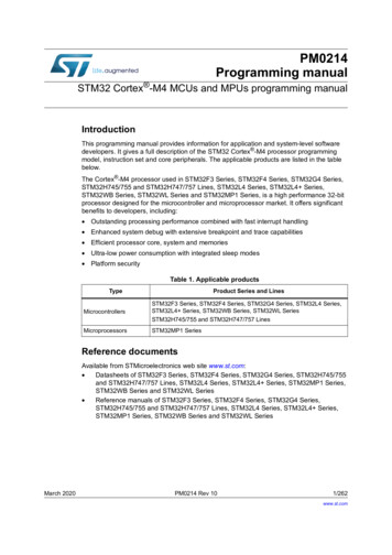
UM2591PCB layout6.1PCB layoutFigure 4. Top layoutLD1red/green LED (COM)CN1 ST-LINK/V2-1Micro-B USB connectorLD4red LED (OC)SB2ST-LINK resetU2STM32G031K8T6U microcontrollerB1RESET or user push-buttonLD2red LED (PWR)UM2591 - Rev 1LD3green LED (USER)page 8/26
UM2591PCB layoutFigure 5. Bottom layoutCN4Arduino Nano connectorCN3Arduino Nano connectorU7ST-LINK/V2-1 microcontrollerJP1IDD measurementUM2591 - Rev 1page 9/26
UM2591Mechanical drawing6.2Mechanical drawingFigure 6. STM32G0 Nucleo-32 board mechanical drawing (in millimeter)6.3Embedded ST-LINK/V2-1The ST-LINK/V2-1 programming and debugging tool is integrated in the STM32G0 Nucleo-32 board.For detailed information about the debugging and programming features of ST-LINK/V2-1, refer to the ST-LINK/V2in-circuit debugger/programmer for STM8 and STM32 user manual (UM1075) and Overview of ST-LINKderivatives technical note (TN1235).Features supported by the ST-LINK/V2-1: USB software re-enumeration Virtual COM port interface on USB Mass storage interface on USBUM2591 - Rev 1page 10/26
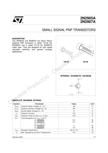
UM2591Power supply USB power management request for more than 100 mA power on USBFeatures not supported on ST-LINK/V2-1: SWIM interface Minimum supported application voltage limited to 3 VKnown limitation: Activating the readout protection on the STM32 target prevents the target application from runningafterwards. The target readout protection must be kept disabled on ST-LINK/V2-1 boards.The embedded ST-LINK/V2-1 is directly connected to the SWD port of the target STM32.6.3.1DriversThe ST-LINK/V2-1 requires a dedicated USB driver, which, for Windows 7 , Windows 8 and Windows 10 , isfound at www.st.com.In case the STM32G0 Nucleo-32 board is connected to the PC before the driver is installed, some STM32G0Nucleo-32 interfaces may be declared as “Unknown” in the PC device manager. In this case, the user must installthe dedicated driver files, and update the driver of the connected device from the device manager a shown in .Note:Prefer using the USB Composite Device handle for a full recovery.Figure 7. USB composite device6.3.2ST-LINK/V2-1 firmware upgradeThe ST-LINK/V2-1 embeds a firmware upgrade mechanism for in-situ upgrade through the USB port. As thefirmware may evolve during the lifetime of the ST-LINK/V2-1 product (for example new functionalities, bug fixes,support for new microcontroller families), it is recommended to visit the www.st.com website before starting to usethe STM32G0 Nucleo-32 board and periodically, to stay up-to-date with the latest firmware version.6.4Power supplyThe power supply is provided either by the host PC through the USB cable, or by an external source: VIN (7 V 12 V), 5V (5 V) or 3V3 (3.3 V) power supply pins on CN4. In case VIN, 5V or 3V3 is used to power theSTM32G0 Nucleo-32 board, this power source must comply with the standard EN-60950-1: 2006 A11/2009, andmust be Safety Extra Low Voltage (SELV) with limited power capability. In case the power supply is 3V3, the STLINK is not powered and cannot be used.6.4.1Power supply input from the USB connectorThe STM32G0 Nucleo-32 board and shield board can be powered from ST-LINK USB connector CN1. Only theST-LINK part is power supplied before the USB enumeration phase, as the host PC only provides 100 mA to theboards at that time. During the USB enumeration, the STM32G0 Nucleo-32 board requires 300 mA of current tothe host PC. If the host is able to provide the required power, the target STM32 microcontroller is powered andred LED LD2 is turned on, thus the STM32G0 Nucleo-32 board and its shield consume a maximum of 300 mAcurrent and not more. If the host is not able to provide the required current, the target STM32 microcontroller andthe shield board are not power supplied. As a consequence the red LED LD2 stays turned off. In such case, it ismandatory to use an external power supply as explained in Section 6.4.2 External power supply inputs.UM2591 - Rev 1page 11/26
UM2591Power supplySB1 is configured according to the maximum current consumption of the board. SB1 can be set to on to informthe host PC that the maximum current consumption does not exceed 100 mA (even when the Arduino Nanoshield is plugged). In such condition, USB enumeration always succeeds since not more than 100 mA isrequested to the host PC. Possible configurations of SB1 are summarized in Table 5.Table 5. SB1 configurationSolder bridge statePower supplySB1 OFF (default)Allowed current300 mA maxUSB power through CN1SB1 ONSB1 (ON/OFF)100 mA maxVIN, 3V3 or 5V powerFor current limitation, refer to Table 6Attention:If the maximum current consumption of the STM32G0 Nucleo-32 board and its shield board exceeds 300 mA, itis mandatory to power the STM32G0 Nucleo-32 board by means of an external power supply connected to VIN, 5V or 3V3.Note:In case the board is powered by a USB charger, there is no USB enumeration. LED LD2 remains offpermanently and the target STM32 is not powered. In this specific case, the SB1 must be set to on, to allow thetarget STM32 to be powered anyway.6.4.2External power supply inputsThe STM32G0 Nucleo-32 board and its shield board can be powered in three different ways from an externalpower supply, depending on the voltage used. The three power sources are summarized in the Table 6.Table 6. External power sourcesInput powernameConnectorpinVoltage rangeMax currentLimitationFrom 7 V to 12 V only and input current capability islinked to input voltage:VINCN4 pin 17 V to 12 V800mA 5VCN4 pin 44.75 V to 5.25 V500mA 3V3CN4 pin 143 V to 3.6 V- 800 mA input current when VIN 7 V 450 mA input current when 7 V VIN 9 V 300 mA input current when 10 V VIN 9 V less than 300 mA input current when VIN 10 VST-LINK not powered and SB2 and SB3 must be OFF.VIN or 5V power supplyWhen powered from VIN or 5 V, it is still possible to use ST-LINK for communication for programming ordebugging only, but it is mandatory to power the board first, using VIN or 5 V, then to connect the USB cable tothe PC. By this way the enumeration succeeds anyway, because of the external power source.The following power sequence procedure must be respected:1.Check that SB1 is OFF2.Connect the external power source to VIN or 5V3.Power on the external power supply 7 V VIN 12 V to VIN, or 5 V for 5V4.Check that red LED LD2 is turned on5.Connect the PC to USB connector CN1If this order is not respected, the board may be powered by VBUS first, then by VIN or 5V, and the following risksmay be encountered:UM2591 - Rev 1page 12/26
UM2591Board functions1.2.If more than 300 mA current is needed by the board, the PC may be damaged or current supplied is limitedby the PC. As a consequence the board is not powered correctly.300 mA is requested at enumeration (since SB1 must be OFF), so the risk exists that the request is rejectedand the enumeration does not succeed if the the PC cannot provide such current. Consequently the board isnot power supplied (LED LD2 remains off). 3V3 power supplyUsing the 3V3 (CN4 pin 14) directly as power input is interesting, for instance if the 3.3 V is provided by a shieldboard. In this case, the ST-LINK is not powered, thus programming and debugging features are not available.When the board is powered by 3V3 (CN4 pin 14), solder bridges SB2 (NRST) and SB3 must be OFF.6.4.3External power supply outputWhen powered by USB or VIN, 5V (CN4 pin 4) can be used as output power supply for an Arduino Nanoshield. In this case, the maximum current of the power source specified in Table 6 must be respected. 3.3V (CN4 pin 14) is also a possible power supply output. The current is limited by the maximum currentcapability of the regulator U3 (500 mA max).6.5Board functions6.5.1LEDsLD1 ST-LINK COM LEDThe bicolor LED LD1 (green, red) provides information about ST-LINK communication status. LD1 default color isred. LD1 turns to green to indicate that communication is in progress between the PC and the ST-LINK, with thefollowing setup: Blinking red: the first USB enumeration with the PC is taking place Red on: the initialization between the PC and ST-LINK is complete Blinking red or green: programming and debugging with target Green on: communication finished and successful Orange on: communication failureLD2 PWRThe red LED indicates that the STM32G0 part is powered and 5 V power is available on CN4 pin 4.LD3 USERThe LD3 USER green LED is connected to the following STM32G031K8T6 I/O: PB3, if t STMicroelectronics, Inc.750 Canyon Drive Suite 300 Coppell, Texas 75019USATelephone: 1 972-466-78459.2IC Compliance StatementIndustry Canada ICES-003 Compliance Label: CAN ICES-3 (B) / NMB-3 (B).UM2591 - Rev 1page 19/26
UM2591CE conformity10CE conformity10.1WarningEN 55032 / CISPR32 (2012) Class A productWarning: this device is compliant with Class A of EN55032 / CISPR32. In a residential environment, thisequipment may cause radio interference.Avertissement : cet équipement est conforme à la Classe A de la EN55032 / CISPR 32. Dans un environnementrésidentiel, cet équipement peut créer des interférences radio.UM2591 - Rev 1page 20/26
UM2591Revision historyTable 11. Document revision historyUM2591 - Rev 1DateVersion25-Jun-20191ChangesInitial release.page 21/26
UM2591ContentsContents1Features. . . . . . . . . . . . . . . . . . . . . . . . . . . . . . . . . . . . . . . . . . . . . . . . . . . . . . . . . . . . . . . . . . . . . . . . . . .22Ordering information . . . . . . . . . . . . . . . . . . . . . . . . . . . . . . . . . . . . . . . . . . . . . . . . . . . . . . . . . . . . . . 332.1Product marking . . . . . . . . . . . . . . . . . . . . . . . . . . . . . . . . . . . . . . . . . . . . . . . . . . . . . . . . . . . . . . . 32.2Products and codification . . . . . . . . . . . . . . . . . . . . . . . . . . . . . . . . . . . . . . . . . . . . . . . . . . . . . . . . 3Development environment . . . . . . . . . . . . . . . . . . . . . . . . . . . . . . . . . . . . . . . . . . . . . . . . . . . . . . . . . 43.1System requirements . . . . . . . . . . . . . . . . . . . . . . . . . . . . . . . . . . . . . . . . . . . . . . . . . . . . . . . . . . . 43.2Development toolchains . . . . . . . . . . . . . . . . . . . . . . . . . . . . . . . . . . . . . . . . . . . . . . . . . . . . . . . . . 43.3Demonstration software . . . . . . . . . . . . . . . . . . . . . . . . . . . . . . . . . . . . . . . . . . . . . . . . . . . . . . . . . 44Conventions. . . . . . . . . . . . . . . . . . . . . . . . . . . . . . . . . . . . . . . . . . . . . . . . . . . . . . . . . . . . . . . . . . . . . . .55Quick start . . . . . . . . . . . . . . . . . . . . . . . . . . . . . . . . . . . . . . . . . . . . . . . . . . . . . . . . . . . . . . . . . . . . . . . .65.16Hardware layout and configuration. . . . . . . . . . . . . . . . . . . . . . . . . . . . . . . . . . . . . . . . . . . . . . . . . 76.1PCB layout . . . . . . . . . . . . . . . . . . . . . . . . . . . . . . . . . . . . . . . . . . . . . . . . . . . . . . . . . . . . . . . . . . . . 76.2Mechanical drawing . . . . . . . . . . . . . . . . . . . . . . . . . . . . . . . . . . . . . . . . . . . . . . . . . . . . . . . . . . . . 96.3Embedded ST-LINK/V2-1. . . . . . . . . . . . . . . . . . . . . . . . . . . . . . . . . . . . . . . . . . . . . . . . . . . . . . . 106.46.56.67Getting started . . . . . . . . . . . . . . . . . . . . . . . . . . . . . . . . . . . . . . . . . . . . . . . . . . . . . . . . . . . . . . . . . 66.3.1Drivers . . . . . . . . . . . . . . . . . . . . . . . . . . . . . . . . . . . . . . . . . . . . . . . . . . . . . . . . . . . . . . . 116.3.2ST-LINK/V2-1 firmware upgrade . . . . . . . . . . . . . . . . . . . . . . . . . . . . . . . . . . . . . . . . . . . . 11Power supply . . . . . . . . . . . . . . . . . . . . . . . . . . . . . . . . . . . . . . . . . . . . . . . . . . . . . . . . . . . . . . . . . 116.4.1Power supply input from the USB connector . . . . . . . . . . . . . . . . . . . . . . . . . . . . . . . . . . . 116.4.2External power supply inputs . . . . . . . . . . . . . . . . . . . . . . . . . . . . . . . . . . . . . . . . . . . . . . 126.4.3External power supply output . . . . . . . . . . . . . . . . . . . . . . . . . . . . . . . . . . . . . . . . . . . . . . 13Board functions . . . . . . . . . . . . . . . . . . . . . . . . . . . . . . . . . . . . . . . . . . . . . . . . . . . . . . . . . . . . . . . 136.5.1LEDs . . . . . . . . . . . . . . . . . . . . . . . . . . . . . . . . . . . . . . . . . . . . . . . . . . . . . . . . . . . . . . . . . 136.5.2Push-button . . . . . . . . . . . . . . . . . . . . . . . . . . . . . . . . . . . . . . . . . . . . . . . . . . . . . . . . . . . 136.5.3Current consumption measurement (IDD). . . . . . . . . . . . . . . . . . . . . . . . . . . . . . . . . . . . . 136.5.4Virtual COM port (VCP): USART . . . . . . . . . . . . . . . . . . . . . . . . . . . . . . . . . . . . . . . . . . . . 14Solder bridges . . . . . . . . . . . . . . . . . . . . . . . . . . . . . . . . . . . . . . . . . . . . . . . . . . . . . . . . . . . . . . . . 14Board connectors . . . . . . . . . . . . . . . . . . . . . . . . . . . . . . . . . . . . . . . . . . . . . . . . . . . . . . . . . . . . . . . .167.1UM2591 - Rev 1Arduino Nano V3 connectors CN3 and CN4. . . . . . . . . . . . . . . . . . . . . . . . . . . . . . . . . . . . . . 16page 22/26
UM2591Contents8STM32G0 Nucleo-32 I/O assignment . . . . . . . . . . . . . . . . . . . . . . . . . . . . . . . . . . . . . . . . . . . . . .189Federal Communications Commission (FCC) and Industry Canada (IC) ComplianceStatements . . . . . . . . . . . . . . . . . . . . . . . . . . . . . . . . . . . . . . . . . . . . . . . . . . . . . . . . . . . . . . . . . . . . . . .19109.1FCC Compliance Statement . . . . . . . . . . . . . . . . . . . . . . . . . . . . . . . . . . . . . . . . . . . . . . . . . . . . 199.2IC Compliance Statement . . . . . . . . . . . . . . . . . . . . . . . . . . . . . . . . . . . . . . . . . . . . . . . . . . . . . . 19CE conformity . . . . . . . . . . . . . . . . . . . . . . . . . . . . . . . . . . . . . . . . . . . . . . . . . . . . . . . . . . . . . . . . . . . .2010.1Warning . . . . . . . . . . . . . . . . . . . . . . . . . . . . . . . . . . . . . . . . . . . . . . . . . . . . . . . . . . . . . . . . . . . . . 20Revision history . . . . . . . . . . . . . . . . . . . . . . . . . . . . . . . . . . . . . . . . . . . . . . . . . . . . . . . . . . . . . . . . . . . . . . .21Contents . . . . . . . . . . . . . . . . . . . . . . . . . . . . . . . . . . . . . . . . . . . . . . . . . . . . . . . . . . . . . . . . . . . . . . . . .
The Arduino Nano V3 . The STM32G0 Nucleo-32 board is a low-cost and easy-to-use development kit, used to evaluate and start a . in-circuit debugger/programmer for STM8 and STM32 user manual (UM1075) and Overview of ST-LINK derivatives technical note (TN1235). Features supported by the ST-LINK/V2-1: