Transcription
Creo Revolve TutorialSetup1. Open Creo ParametricNote: Refer back to the Creo Extrude Tutorial for references and screen shots of the Creo layout2. Set Working Directorya. From the Model Tree navigate to your folder right mouse button Set WorkingDirectory3. Click on the icon New Part name file Revolvetutorial (remember is must be on string nospaces) Ok4. Basic setup features of mouse and hotkeysa. Solid Model Navigation Toolsi. Mouse1. Left Mouse Button: Selects objects2. Roll Bar: Zooms in and out on the model screen.3. Hold Down Roll Bar (Middle Mouse Button): Rotates Model4. Hold Right Mouse Button Down: Gives pop out menu based on thedesign tab.ii. Hotkeys1. a Autoscale2. i Isometric3. d Turns Datums on and offRevolveRevolving is the method of creating a solid by drawing a closed profile and rotatingaround an axis line. The profile may only be drawn on one side of the axis line, this will avoidand intersecting material as the closed profile rotates around the axis1. Under the Model Tab click on the Revolve Icon2. Hold Right Mouse Button in the work area (Black Background) select Define InternalSketch select Front Datum Click Sketch on the Pop-up Window3. Place Axis Line: This is the line you want your profile to spin arounda. Under the Sketch Tab select Centerline Icon to the right of theArrow tool. Note there is another Centerline Tool that says“Centerline” next to the icon, this will not work for an axisb. Left Click on the Origin (Center of the workspace, where the two Datums cross eachother) Move the cursor so the centerline is horizontal Left Click again to placethe centerline. This will place the centerline on top of the Top Datum. You may notbe able to see it. If the user does not place this line then the software will not beable rotate Profile
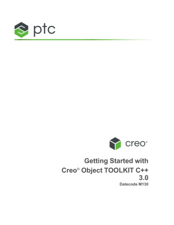
4. Draw the following profile.Avoid creating Equal Length Lines (Software will show an L next to each line if equal)a. Note Profilei. Solid: Placing the Profile on top of the axis line will create solid materialii. Hole: Placing the Profile offset from the axis line will create a hole in thecenter of the objectb. Profile Edgesi. Edges Parallel with the axis line will become curved surfaces on the solidmodelii. Edges Perpendicular to the axis line are linear edgesIf Diameters Do NOT show: Placing Diameter Dimensionsc. Four Clicks of the mouse will be needed to place a dimensiond. Under Sketch Tab click on Normal Icone. Mouse Clicksi. Left Click on Axis Lineii. Left Click on Parallel Edgeiii. Left Click on Axis Line (second time)iv. Middle Mouse Button anywhere to place the dimensionNote Dimensions will appear to measure into blank space. The software is showing wherethe other side of the revolve edge will appearSketch Tab Click the Green Check to lock in the sketch profile This will take you to the Revolve Tab.Buttons are similar to the Extrude (See Extrude Tutorial)
A Solid Object should show up rotate the part around to examine the part. If no solid shows upit means you did not set your axis line. To fix Click on Placement (on the Revolve Info Box) Click Editnext to sketch this will take you back into the sketch Place Axis line Green Checkf.5.Note Blind Distance represents number of degrees of rotation (We will alwaysrotate 360 degrees)g. Note this tutorial is creating a solid, but one can create revolve as a cut. SeeChallenges at the end of the TutorialRevolve Tab Click Green Check to lock in the objectOffset DatumOffset Datums allow users to create new Datums or work surfaces inside or outside of thepart. This allows the user to place a profile in space other than on the default Datums orpredefined solid.6. If Datums are off turn them on Hotkey D7. Go to Model Tab Click on the icon Plane (Pop-up Window will appear, this shows whatDatums have been selected, Allows user to create offset or angled Datums) Select TopDatum In the Datum Pop-up menu the Datum will appear; In the Translation Box enter0.75 (If Datum does not go above the TOP Datum, then type in -.75) If you are having a hardtime seeing which direction it the object is going click Hotkey I (isometric) or Go to View Tab Named Views Default Orientation (Isometric) or any of the others)
8. Extrusion Cuta. Model Extrude Select DTM1 View screen will rotate 90 degrees to the viewerb. Now we will define some edges to measure fromi. Sketch Tab select References Iconii. Click on the following edges seen belowiii. Close References window when donec. Sketch Tab draw a rectangle as seen below Adjust Dimensions Green Check forSketch Extrude Info Tab Select the followingi. Select the Cut Iconii. Cut Through Alliii. Make the cut go up (If wrong direction select Flip Direction)
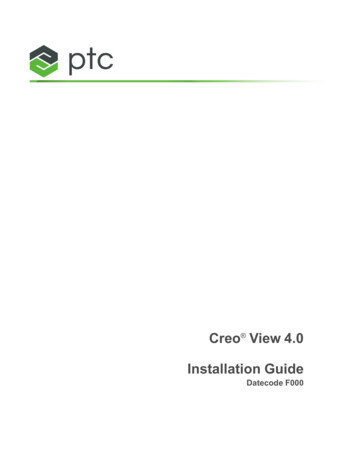
d. Select Green Check (If Final Part does not look correct go to model tree Left Clickon the last extruded Right Click on that extrude Select Edit Definition; this willplace you back into the extrude info box.)9. Adding Materiala. Extrude Icon Hold Right Mouse Button select Define Internal Sketch Select theback surface of the part Draw the following Rectangle with given dimensionsIgnore the hole. Stepcomes later3.00.5000.5000.25Extrude 1.00 into the part
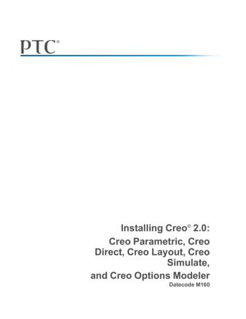
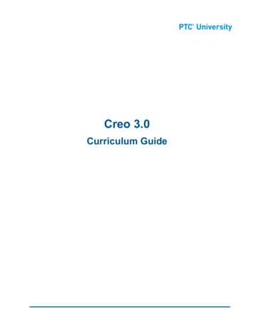
10. Extrude circle cut in the following two location (Note you will do TWO separate extrudes)DIA 0.5000.500Location 1Depth: 0.25Bolt CurveDia. 3.50Location 2Place Reference Circle: Use Circle Tool to draw Set Dimension diameter 3.5 Select circle Right Mouse Button Select ConstructionDepth of Hole Blind 1.00
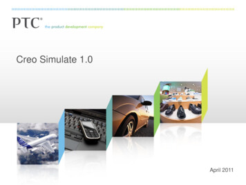
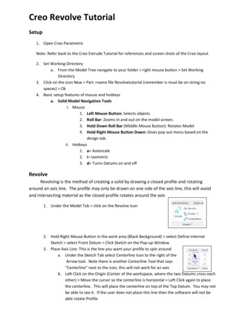
Part Should Look as FollowsRound Edges11. Model Tab select Round Change size to 0.125 Hold Control select the following edges.(Holding Control Key will make all of the edges the same size, not Holding Control Key willmake the edges different sizes0.12512. Green Check
13. Creating a Full Round from an existing edgea. Model Tab select Round select the following edges. Hold Control Key while yourselectingb. Go to Sets Tab in the Round Info bar select Full Round. This will automaticallycreate a full round edge without having to type in a radius size Green CheckGroupingGrouping allows the user to put multiple features (extrude, round, chamfers, etc.) togetherto clean-up the Model Tree or modify the object (Mirror or Pattern)14. First we need to reorder the model tree15. Hold Left Mouse Key down on Round 2 and Drag it below Extrude 2. This will reorder theModel Tree allowing the grouping of the correct two operations. NOTE: If you have morethan 2 Rounds listed you have missed a step. Go back and reread placement of the rounds.16. Hold Control Key down select Extrude 2 and Round 2 Right Mouse Button select Group this will create a group of these two operations which will allows us to mirror bothoperations togetherMirrorMirroring allows the user to select one or multiple existing Solid (Extrude, Revolve, etc.) and reflect theshape over a giving datum. In this tutorial we will be using a pre-existing datum17. In the Model Tree Left Click on Group Local GROUP resulting in selecting it.18. Make sure the Datums are on (Hotkey D or select Datum Icons from View Tab)19. Go to Model Tab Select Mirror Icon (make sure Local Group is still selected) Click onFront Datum either in the Model Tree or in the work space Click Green Check to completethe mirror.
PatternPatterning allows the user to equally space a given extrude. There are multiple ways to pattern.1. Direction- Allows user to equally space a solid in a specified linear direction (Length,Height, or Depth). User can specify one or two directions creating a grid pattern2. Axis- Allows user to rotate a profile based on an axis3. Table- Allows User to create a table and equally or unequally space a solidDirection Pattern20. In the Model Tree select Extrude 3 Go to Model Tab select Pattern21. Rotate the view to Top Viewc. Go to View Tab select Named Views Top View this will rotate your image to aTop View Orientation22. Go to Pattern Tab Click on Dimension Drop Down Menu23. Select the Linear .500 Dimension that measures from the back edge of the part to the centerof the hole. (when selecting the dimension you are not selecting the value for the softwarebut the direction) ( we will only be patterning in one direction)24. In the Dimension Drop Down Menu for Direction 1 place a value of 0.75 and change thenumber of iterations to 3 (See screen shot below) Black dots will show where the holes willappear25. Green Check the Pattern
Axis Pattern26. Click on Extrude 4 on the Model Tree Model Tab select Pattern change the patterntype from Direction to Axis27. Turn on Datums28. Select the Center Axis running down the middle of the part29. Change the iterations to 8 and the degrees to 45 degreesView changed to Right Side from View Named Views Right Side30. Green Check PatternFinal PartChallenges
1. Optional Try to create a revolved cut.Hint: 1. Create a solid to cut away from first.2. Use an offset datum to place cut in the middle of the part
Creo Revolve Tutorial Setup 1. Open Creo Parametric Note: Refer back to the Creo Extrude Tutorial for references and screen shots of the Creo layout 2. Set Working Directory a. From the Model Tree navigate to your folder right mouse button Set Working Directory 3. Click on the icon New Part name file Revolvetutorial (remember is must be on string no spaces) Ok 4. Basic setup features .