Transcription
ESP32 -V3ESP32-U4WDHESP32-S0WDESP32-D0WD – Not Recommended for New Designs (NRND)ESP32-D0WDQ6 – Not Recommended for New Designs (NRND)ESP32-D0WDQ6-V3 – Not Recommended for New Designs (NRND)Version 3.9Espressif SystemsCopyright 2022www.espressif.com
About This DocumentThis document provides the specifications of ESP32 series of chips.Document UpdatesPlease always refer to the latest version on ments.Revision HistoryFor any changes to this document over time, please refer to the last page.Documentation Change NotificationEspressif provides email notifications to keep customers updated on changes to technical documentation.Please subscribe at www.espressif.com/en/subscribe. Note that you need to update your subscription to receivenotifications of new products you are not currently subscribed to.CertificationDownload certificates for Espressif products from www.espressif.com/en/certificates.
ContentsContents1Overview81.1Featured Solutions81.1.1Ultra-Low-Power Solution81.1.2Complete Integration Solution81.2Wi-Fi Key Features81.3Bluetooth Key Features91.4MCU and Advanced Features91.4.1CPU and Memory91.4.2Clocks and Timers101.4.3Advanced Peripheral Interfaces101.4.4Security101.5Applications (A Non-exhaustive List)111.6Block Diagram122Pin Definitions132.1Pin Layout132.2Pin Description152.3Power Scheme192.4Strapping Pins213Functional Description233.1CPU and Memory233.1.1CPU233.1.2Internal Memory233.1.3External Flash and SRAM243.1.4Memory Map243.23.33.43.53.6Timers and Watchdogs263.2.164-bit Timers263.2.2Watchdog Timers26System Clocks273.3.1CPU Clock273.3.2RTC Clock273.3.3Audio PLL Clock27Radio273.4.12.4 GHz Receiver283.4.22.4 GHz Transmitter283.4.3Clock Generator28Wi-Fi283.5.1Wi-Fi Radio and Baseband293.5.2Wi-Fi MAC29Bluetooth293.6.129Bluetooth Radio and BasebandEspressif Systems3Submit Documentation FeedbackESP32 Series Datasheet v3.8
Contents3.6.2Bluetooth Interface303.6.3Bluetooth Stack303.6.4Bluetooth Link Controller303.7RTC and Low-Power Management314Peripherals and Sensors334.1Descriptions of Peripherals and Sensors334.1.1General Purpose Input/Output Interface (GPIO)334.1.2Analog-to-Digital Converter (ADC)334.1.3Hall Sensor344.1.4Digital-to-Analog Converter (DAC)344.1.5Touch Sensor344.1.6Ultra-Low-Power (ULP) Coprocessor354.1.7Ethernet MAC Interface354.1.8SD/SDIO/MMC Host Controller354.1.9SDIO/SPI Slave Controller364.1.10 Universal Asynchronous Receiver Transmitter (UART)364.1.11 I2C Interface364.1.12 I2S Interface374.1.13 Infrared Remote Controller (RMT)374.1.14 Pulse Counter (PCNT)374.1.15 Pulse Width Modulation (PWM)374.1.16 LED PWM374.1.17 Serial Peripheral Interface (SPI)384.1.18 TWAI Controller384.1.19 Accelerator384.2Peripheral Pin Configurations395Electrical Characteristics445.1Absolute Maximum Ratings445.2Recommended Operating Conditions445.3DC Characteristics (3.3 V, 25 C)455.4Reliability Qualifications455.5RF Power-Consumption Specifications465.6Wi-Fi Radio465.7Bluetooth Radio475.7.1Receiver – Basic Data Rate475.7.2Transmitter – Basic Data Rate475.7.3Receiver – Enhanced Data Rate485.7.4Transmitter – Enhanced Data Rate485.86Bluetooth LE Radio495.8.1Receiver495.8.2Transmitter50Package InformationEspressif Systems514Submit Documentation FeedbackESP32 Series Datasheet v3.8
Contents7Part Number and Ordering Information528Related Documentation and Resources53Appendix A – ESP32 Pin Lists54A.1. Notes on ESP32 Pin Lists54A.2. GPIO Matrix56A.3. Ethernet MAC61A.4. IO MUX61Revision History63Espressif Systems5Submit Documentation FeedbackESP32 Series Datasheet v3.8
List of TablesList of Tables1Pin Description152Pin-to-Pin Mapping Between Chip and Embedded Flash/PSRAM183Connection Between Chip and External Flash/PSRAM184Description of ESP32 Power-up and Reset Timing Parameters205Strapping Pins216Parameter Descriptions of Setup and Hold Times for the Strapping Pins227Memory and Peripheral Mapping258Power Consumption by Power Modes319ADC Characteristics3310ADC Calibration Results3411Capacitive-Sensing GPIOs Available on ESP323412Peripheral Pin Configurations3913Absolute Maximum Ratings4414Recommended Operating Conditions4415DC Characteristics (3.3 V, 25 C)4516Reliability Qualifications4517RF Power-Consumption Specifications4618Wi-Fi Radio Characteristics4619Receiver Characteristics – Basic Data Rate4720Transmitter Characteristics – Basic Data Rate4721Receiver Characteristics – Enhanced Data Rate4822Transmitter Characteristics – Enhanced Data Rate4923Receiver Characteristics – Bluetooth LE4924Transmitter Characteristics – Bluetooth LE5025ESP32 Ordering Information5226Notes on ESP32 Pin Lists5427GPIO Matrix5628Ethernet MAC61Espressif Systems6Submit Documentation FeedbackESP32 Series Datasheet v3.8
List of FiguresList of Figures1Functional Block Diagram122ESP32 Pin Layout (QFN 6*6, Top View)133ESP32 Pin Layout (QFN 5*5, Top View)144ESP32 Power Scheme195ESP32 Power-up and Reset Timing206Setup and Hold Times for the Strapping Pins227Address Mapping Structure248QFN48 (6x6 mm) Package519QFN48 (5x5 mm) Package5110ESP32 Part Number Description52Espressif Systems7Submit Documentation FeedbackESP32 Series Datasheet v3.8
1 Overview1 OverviewESP32 is a single 2.4 GHz Wi-Fi-and-Bluetooth combo chip designed with the TSMC ultra-low-power 40 nmtechnology. It is designed to achieve the best power and RF performance, showing robustness, versatility andreliability in a wide variety of applications and power scenarios.The ESP32 series of chips includes ESP32-D0WD-V3, ESP32-D0WDR2-V3, ESP32-U4WDH, ESP32-S0WD,ESP32-D0WDQ6-V3 (NRND), ESP32-D0WD (NRND), and ESP32-D0WDQ6 (NRND), among which,ESP32-D0WD-V3, ESP32-D0WDR2-V3, ESP32-U4WDH, and ESP32-D0WDQ6-V3 (NRND) are based on ECOV3 wafer.For details on part numbers and ordering information, please refer to Section 7.For details on ECO V3 instructions, please refer to ESP32 ECO V3 User Guide.1.1 Featured Solutions1.1.1 Ultra Low Power SolutionESP32 is designed for mobile, wearable electronics, and Internet-of-Things (IoT) applications. It features all thestate-of-the-art characteristics of low-power chips, including fine-grained clock gating, multiple power modes,and dynamic power scaling. For instance, in a low-power IoT sensor hub application scenario, ESP32 is wokenup periodically only when a specified condition is detected. Low-duty cycle is used to minimize the amount ofenergy that the chip expends. The output of the power amplifier is also adjustable, thus contributing to anoptimal trade-off between communication range, data rate and power consumption.Note:For more information, refer to Section 3.7 RTC and Low-Power Management.1.1.2 Complete Integration SolutionESP32 is a highly-integrated solution for Wi-Fi-and-Bluetooth IoT applications, with around 20 externalcomponents. ESP32 integrates an antenna switch, RF balun, power amplifier, low-noise receive amplifier, filters,and power management modules. As such, the entire solution occupies minimal Printed Circuit Board (PCB)area.ESP32 uses CMOS for single-chip fully-integrated radio and baseband, while also integrating advancedcalibration circuitries that allow the solution to remove external circuit imperfections or adjust to changes inexternal conditions. As such, the mass production of ESP32 solutions does not require expensive andspecialized Wi-Fi testing equipment.1.2 Wi Fi Key Features 802.11 b/g/n 802.11 n (2.4 GHz), up to 150 Mbps WMM TX/RX A-MPDU, RX A-MSDUEspressif Systems8Submit Documentation FeedbackESP32 Series Datasheet v3.8
1 Overview Immediate Block ACK Defragmentation Automatic Beacon monitoring (hardware TSF) 4 virtual Wi-Fi interfaces Simultaneous support for Infrastructure Station, SoftAP, and Promiscuous modesNote that when ESP32 is in Station mode, performing a scan, the SoftAP channel will be changed. Antenna diversityNote:For more information, please refer to Section 3.5 Wi-Fi.1.3 Bluetooth Key Features Compliant with Bluetooth v4.2 BR/EDR and Bluetooth LE specifications Class-1, class-2 and class-3 transmitter without external power amplifier Enhanced Power Control 9 dBm transmitting power NZIF receiver with –94 dBm Bluetooth LE sensitivity Adaptive Frequency Hopping (AFH) Standard HCI based on SDIO/SPI/UART High-speed UART HCI, up to 4 Mbps Bluetooth 4.2 BR/EDR Bluetooth LE dual mode controller Synchronous Connection-Oriented/Extended (SCO/eSCO) CVSD and SBC for audio codec Bluetooth Piconet and Scatternet Multi-connections in Classic Bluetooth and Bluetooth LE Simultaneous advertising and scanning1.4 MCU and Advanced Features1.4.1 CPU and Memory Xtensa single-/dual-core 32-bit LX6 microprocessor(s) CoreMark score:– 1 core at 240 MHz: 504.85 CoreMark; 2.10 CoreMark/MHz– 2 cores at 240 MHz: 994.26 CoreMark; 4.14 CoreMark/MHz 448 KB ROMEspressif Systems9Submit Documentation FeedbackESP32 Series Datasheet v3.8
1 Overview 520 KB SRAM 16 KB SRAM in RTC QSPI supports multiple flash/SRAM chips1.4.2 Clocks and Timers Internal 8 MHz oscillator with calibration Internal RC oscillator with calibration External 2 MHz 60 MHz crystal oscillator (40 MHz only for Wi-Fi/Bluetooth functionality) External 32 kHz crystal oscillator for RTC with calibration Two timer groups, including 2 64-bit timers and 1 main watchdog in each group One RTC timer RTC watchdog1.4.3 Advanced Peripheral Interfaces 34 programmable GPIOs 12-bit SAR ADC up to 18 channels 2 8-bit DAC 10 touch sensors 4 SPI 2 I2S 2 I2C 3 UART 1 host (SD/eMMC/SDIO) 1 slave (SDIO/SPI) Ethernet MAC interface with dedicated DMA and IEEE 1588 support TWAI , compatible with ISO 11898-1 (CAN Specification 2.0) RMT (TX/RX) Motor PWM LED PWM up to 16 channels Hall sensor1.4.4 Security Secure boot Flash encryption 1024-bit OTP, up to 768-bit for customersEspressif Systems10Submit Documentation FeedbackESP32 Series Datasheet v3.8
1 Overview Cryptographic hardware acceleration:– AES– Hash (SHA-2)– RSA– ECC– Random Number Generator (RNG)1.5 Applications (A Non exhaustive List)– Agriculture robotics Generic Low-power IoT Sensor Hub Generic Low-power IoT Data Loggers Audio Applications Cameras for Video Streaming– Internet music players Over-the-top (OTT) Devices– Live streaming devices Speech Recognition– Internet radio players Image Recognition– Audio headsets Mesh Network Health Care Applications Home Automation– Health monitoring– Light control– Baby monitors– Smart plugs Wi-Fi-enabled Toys– Smart door locks– Remote control toys Smart Building– Proximity sensing toys– Smart lighting– Educational toys– Energy monitoring Wearable Electronics Industrial Automation– Industrial wireless control– Smart watches– Industrial robotics– Smart bracelets Retail & Catering Applications Smart Agriculture– Smart greenhouses– POS machines– Smart irrigation– Service robotsEspressif Systems11Submit Documentation FeedbackESP32 Series Datasheet v3.8
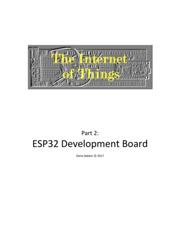
1 Overview1.6 Block I2SWi-Fi MACWi-FibasebandRFtransmitSDIOUARTTWAI ETHCryptographic hardwareaccelerationCore and memory2 or 1 x Xtensa 32bit LX6 ollerSwitchEmbeddedFlash or PSRAMSRAMSHARSAAESRNGTouch rsFigure 1: Functional Block DiagramNote:Products in the ESP32 series differ from each other in terms of their support for embedded flash or PSRAM and thenumber of CPUs they have. For details, please refer to Section 7 Part Number and Ordering Information.Espressif Systems12Submit Documentation FeedbackESP32 Series Datasheet v3.8
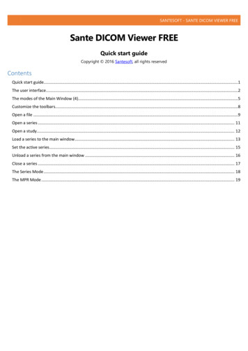
2 Pin Definitions2 Pin DefinitionsCAP1CAP2VDDAXTAL PXTAL NVDDAGPIO21U0TXDU0RXDGPIO22GPIO19VDD3P3 CPU4847464544434241403938372.1 Pin LayoutVDDA136GPIO23LNA IN235GPIO18VDD3P3334GPIO5VDD3P3433SD DATA 1SENSOR VP532SD DATA 0SENSOR CAPP631SD CLKSENSOR CAPN730SD CMDSENSOR VN829SD DATA 3CHIP PU928SD DATA 2VDET 11027GPIO17VDET 21126VDD SDIO32K XP1225GPIO1613141516171819202122232432K XNGPIO25GPIO26GPIO27MTMSMTDIVDD3P3 RTCMTCKMTDOGPIO2GPIO0GPIO4ESP3249 GNDFigure 2: ESP32 Pin Layout (QFN 6*6, Top View)Espressif Systems13Submit Documentation FeedbackESP32 Series Datasheet v3.8
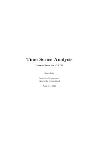
CAP1CAP2VDDAXTAL PXTAL NVDDAGPIO21U0TXDU0RXDGPIO22484746454443424140392 Pin DefinitionsVDDA138GPIO19LNA IN237VDD3P3 CPUVDD3P3336GPIO23VDD3P3435GPIO18SENSOR VP534GPIO5SENSOR CAPP633SD DATA 1SENSOR CAPN732SD DATA 0SENSOR VN831SD CLKCHIP PU930SD CMDVDET 11029SD DATA 3VDET 21128SD DATA 232K XP1227GPIO1732K XN1326VDD 27MTMSMTDIVDD3P3 RTCMTCKMTDOGPIO2GPIO0GPIO4ESP3249 GNDFigure 3: ESP32 Pin Layout (QFN 5*5, Top View)Note:For details on ESP32’s part numbers and the corresponding packaging, please refer to Section 7 Part Number and OrderingInformation.Espressif Systems14Submit Documentation FeedbackESP32 Series Datasheet v3.8
2 Pin DefinitionsEspressif Systems2.2 Pin DescriptionTable 1: Pin DescriptionNameNo.TypeFunctionAnalogAnalog power supply (2.3 V 3.6 V)VDDA1PLNA IN2I/OVDD3P33PAnalog power supply (2.3 V 3.6 V)VDD3P34PAnalog power supply (2.3 V 3.6 V)RF input and outputVDD3P3 RTC5IGPIO36, ADC1 CH0,RTC GPIO0SENSOR CAPP6IGPIO37, ADC1 CH1,RTC GPIO1SENSOR CAPN7IGPIO38, ADC1 CH2,RTC GPIO2SENSOR VN8IGPIO39, ADC1 CH3,RTC GPIO315Submit Documentation FeedbackSENSOR VPHigh: On; enables the chipCHIP PU9ILow: Off; the chip powers offNote: Do not leave the CHIP PU pin floating.ESP32 Series Datasheet v3.8VDET 110IGPIO34, ADC1 CH6,RTC GPIO4VDET 211IGPIO35, ADC1 CH7,RTC GPIO532K XP12I/OGPIO32, ADC1 CH4,RTC GPIO9,TOUCH9,32K XP (32.768 kHz crystal oscillator input)32K XN13I/OGPIO33, ADC1 CH5,RTC GPIO8,TOUCH8,32K XN (32.768 kHz crystal oscillator output)GPIO2514I/OGPIO25, ADC2 CH8,RTC GPIO6,DAC 1,EMAC RXD0GPIO2615I/OGPIO26, ADC2 CH9,RTC GPIO7,DAC 2,EMAC RXD1GPIO2716I/OGPIO27, ADC2 CH7,RTC GPIO17, TOUCH7,EMAC RX DVMTMS17I/OGPIO14, ADC2 CH6,RTC GPIO16, TOUCH6,EMAC TXD2,HSPICLK,HS2 CLK,MTDI18I/OGPIO12, ADC2 CH5,RTC GPIO15, TOUCH5,EMAC TXD3,HSPIQ,HS2 DATA2, SD DATA2,MTDIVDD3P3 RTC19PMTCK20I/OGPIO13, ADC2 CH4,RTC GPIO14, TOUCH4,EMAC RX ER, HSPID,HS2 DATA3, SD DATA3,MTCKMTDO21I/OGPIO15, ADC2 CH3,RTC GPIO13, TOUCH3,EMAC RXD3,HS2 CMD,MTDOSD CLK,MTMSInput power supply for RTC IO (2.3 V 3.6 V)HSPICS0,SD CMD,
No.TypeFunctionGPIO222I/OGPIO2,ADC2 CH2,RTC GPIO12, TOUCH2,GPIO023I/OGPIO0,ADC2 CH1,RTC GPIO11, TOUCH1,EMAC TX CLK, CLK OUT1,GPIO424I/OGPIO4,ADC2 CH0,RTC GPIO10, TOUCH0,EMAC TX ER,HSPIWP,HSPIHD,VDD SDIO16Submit Documentation FeedbackGPIO1625I/OGPIO16, HS1 DATA4,U2RXD,EMAC CLK OUTVDD SDIO26PGPIO1727I/OGPIO17, HS1 DATA5,U2TXD,EMAC CLK OUT 180SD DATA 228I/OGPIO9,HS1 DATA2,U1RXD,SD DATA2,SPIHDSD DATA 329I/OGPIO10, HS1 DATA3,U1TXD,SD DATA3,SPIWPSD CMD30I/OGPIO11, HS1 CMD,U1RTS,SD CMD,SPICS0SD CLK31I/OGPIO6,HS1 CLK,U1CTS,SD CLK,SPICLKSD DATA 032I/OGPIO7,HS1 DATA0,U2RTS,SD DATA0,SPIQSD DATA 133I/OGPIO8,HS1 DATA1,U2CTS,SD DATA1,SPIDOutput power supply: 1.8 V or the same voltage as VDD3P3 RTCVDD3P3 CPUGPIO534I/OGPIO5,HS1 DATA6,VSPICS0,EMAC RX CLKGPIO1835I/OGPIO18, HS1 DATA7,VSPICLKGPIO2336I/OGPIO23, HS1 STROBE, VSPIDVDD3P3 CPU37PGPIO1938I/OGPIO19, U0CTS,VSPIQ,EMAC TXD0GPIO2239I/OGPIO22, U0RTS,VSPIWP,EMAC TXD1U0RXD40I/OGPIO3,U0RXD,CLK OUT2U0TXD41I/OGPIO1,U0TXD,CLK OUT3,EMAC RXD2GPIO2142I/OGPIO21,VSPIHD,EMAC TX ENInput power supply for CPU IO (1.8 V 3.6 V)ESP32 Series Datasheet v3.8AnalogVDDA43PAnalog power supply (2.3 V 3.6 V)XTAL N44OExternal crystal outputXTAL P45IExternal crystal inputVDDA46PAnalog power supply (2.3 V 3.6 V)CAP247IConnects to a 3.3 nF (10%) capacitor and 20 kΩ resistor in parallel to CAP1HS2 DATA0, SD DATA0HS2 DATA1, SD DATA12 Pin DefinitionsEspressif SystemsName
No.TypeFunctionCAP148IConnects to a 10 nF series capacitor to groundGND49PGroundNote:For a quick reference guide to using the IO MUX, Ethernet MAC, and GIPO Matrix pins of ESP32, please refer to Appendix ESP32 Pin Lists.2 Pin DefinitionsEspressif SystemsName17Submit Documentation FeedbackESP32 Series Datasheet v3.8
2 Pin DefinitionsTable 2 lists the pin-to-pin mapping between the chip and the embedded flash/PSRAM. The chip pins listed hereare not recommended for other usage. For the data port connection between ESP32 and external flash/PSRAMplease refer to Table 3.Table 2: Pin to Pin Mapping Between Chip and Embedded Flash/PSRAMESP32 U4WDHEmbedded Flash (4 MB)SD DATA 1IO0/DIGPIO17IO1/DOSD DATA 0IO2/WP#SD CMDIO3/HOLD#SD CLKCLKGPIO16CS#GNDVSSVDD SDIOVDDESP32 D0WDR2 V3Embedded PSRAM (2 MB)SD DATA 1SIO0/SISD DATA 0SIO1/SOSD DATA 3SIO2SD DATA 2SIO3SD CLKSCLKGPIO16CE#GNDVSSVDD SDIOVDDTable 3: Connection Between Chip and External Flash/PSRAMChip PinExternal FlashSD DATA1/SPIDIO0/DISD DATA0/SPIQIO1/DOSD DATA3/SPIWPIO2/WP#SD DATA2/SPIHDIO3/HOLD#SD CLKCLKSD CMDCS#GNDVSSVDD SDIOVDDChip PinEspressif SystemsExternal PSRAMSD DATA 1SIO0/SISD DATA 0SIO1/SOSD DATA 3SIO2SD DATA 2SIO3SD CLK/GPIO17*SCLKGPIO16CE#GNDVSSVDD SDIOVDD18Submit Documentation FeedbackESP32 Series Datasheet v3.8
2 Pin DefinitionsNote:SD CLK and GPIO17 pins are available to connect to the SCLK signal of external PSRAM. If SD CLK pin is selected, one GPIO (i.e., GPIO17) will be saved. The saved GPIO can be used for other purposes.This connection has passed internal tests, but relevant certification has not been completed. Or GPIO17 pin is used to connect to the SCLK signal. This connection has passed relevant certification, seecertificates for ESP32-WROVER-E.Please select the proper pin for your specific applications.2.3 Power SchemeESP32’s digital pins are divided into three different power domains: VDD3P3 RTC VDD3P3 CPU VDD SDIOVDD3P3 RTC is also the input power supply for RTC and CPU.VDD3P3 CPU is also the input power supply for CPU.VDD SDIO connects to the output of an internal LDO whose input is VDD3P3 RTC. When VDD SDIO isconnected to the same PCB net together with VDD3P3 RTC, the internal LDO is disabled automatically. Thepower scheme diagram is shown below:VDD3P3 RTC1.8 VLDOR 6ΩLDO1.1 VVDD3P3 CPULDO1.1 VVDD SDIO3.3 V/1.8 VSDIORTCCPUDomainDomainDomainFigure 4: ESP32 Power SchemeEspressif Systems19Submit Documentation FeedbackESP32 Series Datasheet v3.8
2 Pin DefinitionsThe internal LDO can be configured as having 1.8 V, or the same voltage as VDD3P3 RTC. It can be powered offvia software to minimize the current of flash/SRAM during the Deep-sleep mode.Notes on CHIP PU: The illustration below shows the ESP32 power-up and reset timing. Details about the parameters are listedin Table 4.t0t1VDD3P3 RTC MinVDDVIL nRSTCHIP PUFigure 5: ESP32 Power up and Reset TimingTable 4: Description of ESP32 Power up and Reset Timing ParametersParameterst0t1DescriptionTime between the 3.3 V rails being brought up and CHIP PU beingactivatedDuration of CHIP PU signal level VIL nRST (refer to its value inTable 15 DC Characteristics) to reset the chipMin.Unit50µs50µs In scenarios where ESP32 is powered on and off repeatedly by switching the power rails, while there is alarge capacitor on the VDD33 rail and CHIP PU and VDD33 are connected, simply switching off theCHIP PU power rail and immediately switching it back on may cause an incomplete power discharge cycleand failure to reset the chip adequately.An additional discharge circuit may be required to accelerate the discharge of the large capacitor on railVDD33, which will ensure proper power-on-reset when the ESP32 is powered up again. When a battery is used as the power supply for the ESP32 series of chips and modules, a supply voltagesupervisor is recommended, so that a boot failure due to low voltage is avoided. Users are recommendedto pull CHIP PU low if the power supply for ESP32 is below 2.3 V.Notes on power supply: The operating voltage of ESP32 ranges from 2.3 V to 3.6 V. When using a single-power supply, therecommended voltage of the power supply is 3.3 V, and its recommended output current is 500 mA ormore. When VDD SDIO 1.8 V is used as the power supply for external flash/PSRAM, a 2 kΩ grounding resistorshould be added to VDD SDIO. For the circuit design, please refer to Figure ESP32 WROVERSchematics, in ESP32-WROVER Datasheet. When the three digital power supplies are used to drive peripherals, e.g., 3.3 V flash, they should complywith the peripherals’ specifications.Espressif Systems20Submit Documentation FeedbackESP32 Series Datasheet v3.8
2 Pin Definitions2.4 Strapping PinsThere are five strapping pins: MTDI GPIO0 GPIO2 MTDO GPIO5Software can read the values of these five bits from register ”GPIO STRAPPING”.During the chip’s system reset release (power-on-reset, RTC watchdog reset and brownout reset), the latches ofthe strapping pins sample the voltage level as strapping bits of ”0” or ”1”, and hold these bits until the chip ispowered down or shut down. The strapping bits configure the device’s boot mode, the operating voltage ofVDD SDIO and other initial system settings.Each strapping pin is connected to its internal pull-up/pull-down during the chip reset. Consequently, if astrapping pin is unconnected or the connected external circuit is high-impedance, the internal weakpull-up/pull-down will determine the default input level of the strapping pins.To change the strapping bit values, users can apply the external pull-down/pull-up resistances, or use the hostMCU’s GPIOs to control the voltage level of these pins when powering on the chip.After reset release, the strapping pins work as normal-function pins.Refer to Table 5 for a detailed boot-mode configuration by strapping pins.Table 5: Strapping PinsVoltage of Internal LDO (VDD SDIO)PinMTDIDefault3.3 V1.8 VPull-down01Booting ModePinDefaultSPI BootDownload ing/Disabling Debugging Log Print over U0TXD During BootingPinDefaultU0TXD ActiveU0TXD SilentMTDOPull-up10Timing of SDIO SlaveFE SamplingFE SamplingRE SamplingRE SamplingPinDefaultFE OutputRE OutputFE OutputRE OutputMTDOPull-up0011GPIO5Pull-up0101Note: FE: falling-edge, RE: rising-edge. Firmware can configure register bits to change the settings of “Voltage of Internal LDO (VDD SDIO)” and “TimingEspressif Systems21Submit Documentation FeedbackESP32 Series Datasheet v3.8
2 Pin Definitionsof SDIO Slave”, after booting. For ESP32 chips that contain an embedded flash or PSRAM, users need to note the logic level of MTDI. Forexample, ESP32-U4WDH contains an embedded flash that operates at 3.3 V, therefore, the MTDI should be low.The illustration below shows the setup and hold times for the strapping pins before and after the CHIP PU signalgoes high. Details about the parameters are listed in Table 6.t0CHIP PUt1VIL nRSTVIHStrapping pinFigure 6: Setup and Hold Times for the Strapping PinsTable 6: Parameter Descriptions of Setup and Hold Times for the Strapping PinsParametersDescriptionMin.Unitt0Setup time before CHIP PU goes from low to high0mst1Hold time after CHIP PU goes high1msEspressif Systems22Submit Documentation FeedbackESP32 Series Datasheet v3.8
3 Functional Description3 Functional DescriptionThis chapter describes the functions integrated in ESP32.3.1 CPU and Memory3.1.1 CPUESP32 contains one or two low-power Xtensa 32-bit LX6 microprocessor(s) with the following features: 7-stage pipeline to support the clock frequency of up to 240 MHz (160 MHz for ESP32-S0WD) 16/24-bit Instruction Set provides high code-density Support for Floating Point Unit Support for DSP instructions, such as a 32-bit multiplier, a 32-bit divider, and a 40-bit MAC Support for 32 interrupt vectors from about 70 interrupt sourcesThe single-/dual-CPU interfaces include: Xtensa RAM/ROM Interface for instructions and data Xtensa Local Memory Interface for fast peripheral register access External and internal interrupt sources JTAG for debugging3.1.2 Internal MemoryESP32’s internal memory includes: 448 KB of ROM for booting and core functions 520 KB of on-chip SRAM for data and instructions 8 KB of SRAM in RTC, which is called RTC FAST Memory and can be used for data storage; it is accessedby the main CPU during RTC Boot from the Deep-sleep mode. 8 KB of SRAM in RTC, which is called RTC SLOW Memory and can be accessed by the ULP coprocessorduring the Deep-sleep mode. 1 Kbit of eFuse: 256 bits are used for the system (MAC address and chip configuration) and the remaining768 bits are reserved for customer applications, including flash-encryption and chip-ID. Embedded flash or PSRAMNote:Products in the ESP32 series differ from each other, in terms of their support for embedded flash or PSRAM and the sizeof them. For details, please refer to Section 7 Part Number and Ordering Information.Espressif Systems23Submit Documentation FeedbackESP32 Series Datasheet v3.8
3 Functional Description3.1.3 External Flash and SRAMESP32 supports multiple external QSPI flash and SRAM chips. More details can be found in Chapter SPI in theESP32 Technical Reference Manual. ESP32 also supports hardware encryption/decryption based on AES toprotect developers’ programs and data in flash.ESP32 can access the external QSPI flash and SRAM through high-speed caches. Up to 16 MB of external flash can be mapped into CPU instruction memory space and read-only memoryspace simultaneously.– When external flash is mapped into CPU instruction memory space, up to 11 MB 248 KB can bemapped at a time. Note that if more than 3 MB 248 KB are mapped, cache performance will bereduced due to speculative reads by the CPU.– When external flash is mapped into read-only data memory space, up to 4 MB can be mapped at atime. 8-bit, 16-bit and 32-bit reads are supported. External SRAM can be mapped into CPU data memory space. SRAM up to 8 MB is supported and up to 4MB can be mapped at a time. 8-bit, 16-bit and 32-bit reads and writes are supported.Note:After ESP32 is initialized, firmware can customize the mapping of external SRAM or flash into the CPU address space.3.1.4 Memory MapThe structure of address mapping is shown in Figure 7. The memory and peripheral mapping of ESP32 is shownin Table 7.Figure 7: Address Mapping StructureEspressif Systems24Submit Documentation FeedbackESP32 Series Datasheet v3.8
3 Functional DescriptionTable 7: Memory and Peripheral MappingCategoryEmbeddedMemoryTargetStart AddressEnd AddressSizeInternal ROM 00x4000 00000x4005 FFFF384 KBInternal ROM 10x3FF9 00000x3FF9 FFFF64 KBInternal SRAM 00x4007 00000x4009 FFFF192 KB0x3FFE 00000x3FFF FFFF0x400A 00000x400B FFFF0x3FFA E0000x3FFD FFFF0x3FF8 00000x3FF8 1FFF0x400C 00000x400C 1FFF0x5000 00000x5000 1FFF8 KB0x3F40 00000x3F7F FFFF4 MBInternal SRAM 1Internal SRAM 2RTC FAST MemoryRTC SLOW MemoryExternalMemoryPeripheralEspressif SystemsExternal Flash128 KB200 KB8 KB0x400C 20000x40BF FFFF11 MB 248 KBExternal RAM0x3F80 00000x3FBF FFFF4 MBDPort Register0x3FF0 00000x3FF0 0FFF4 KBAES Accelerator0x3FF0 10000x3FF0 1FFF4 KBRSA Accelerator0x3FF0 20000x3FF0 2FFF4 KBSHA Accelerator0x3FF0 30000x3FF0 3FFF4 KBSecure Boot0x3FF0 40000x3FF0 4FFF4 KBCache MMU Table0x3FF1 00000x3FF1 3FFF16 KBPID Controller0x3FF1 F0000x3FF1 FFFF4 KBUART00x3FF4 00000x3FF4 0FFF4 KBSPI10x3FF4 20000x3FF4 2FFF4 KBSPI00x3FF4 30000x3FF4 3FFF4 KBGPIO0x3FF4 40000x3FF4 4FFF4 KBRTC0x3FF4 80000x3FF4 8FFF4 KBIO MUX0x3FF4 90000x3FF4 9FFF4 KBSDIO Slave0x3FF4 B0000x3FF4 BFFF4 KBUDMA10x3FF4 C0000x3FF4 CFFF4 KBI2S00x3FF4 F0000x3FF4 FFFF4 KBUART10x3FF5 00000x3FF5 0FFF4 KBI2C00x3FF5 30000x3FF5 3FFF4 KBUDMA00x3FF5 40000x3FF5 4FFF4 KBSDIO Slave0x3FF5 50000x3FF5 5FFF4 KBRMT0x3FF5 60000x3FF5 6FFF4 KBPCNT0x3FF5 70000x3FF5 7FFF4 KBSDIO Slave0x3FF5 80000x3FF5 8FFF4 KBLED PWM0x3FF5 90000x3FF5 9FFF4 KBeFuse Controller0x3FF5 A0000x3FF5 AFFF4 KBFlash Encryption0x3FF5 B0000x3FF5 BFFF4 KBPWM00x3FF5 E0000x3FF5 EFFF4 KBTIMG00x3FF5 F0000x3FF5 FFFF4 KBTIMG10x3FF6 00000x3FF6 0FFF4 KBSPI20x3FF6 40000x3FF6 4FFF4 KBSPI30x3FF6 50000x3FF6 5FFF4 KB25Submit Documentation FeedbackESP32 Series Datasheet v3.8
3 Functional DescriptionCategoryPeripheralTargetStart AddressEnd AddressSizeSYSCON0x3FF6 60000x3FF6 6FFF4 KBI2C10x3FF6 70000x3FF6 7FFF4 KBSDMMC0x3FF6 80000x3FF6 8FFF4 KBEMAC0x3FF6 90000x3FF6 AFFF8 KBTWAI0x3FF6 B0000x3FF6 BFFF4 KBPWM10x3FF6 C0000x3FF6 CFFF4 KBI2S10x3FF6 D0000x3FF6 DFFF4 KBUART20x3FF6 E0000x3FF6 EFFF4 KBPWM20x3FF6 F0000x3FF6 FFFF4 KBPWM30x3FF7 00000x3FF7 0FFF4 KBRNG0x3FF7 50000x3FF7 5FFF4 KB3.2 Timers and Watchdogs3.2.1 64 bit TimersThere are four general-purpose timers embedded in the chip. They are all 64-bit generic timers which are basedon 16-bit prescalers and 64-bit auto-reload-capable up/down-timers.The timers feature: A 16-bit clock prescaler, from 2 to 65536 A 64-bit timer Configurable up/down timer: incrementing or decrementing Halt and resume of time-base counter Auto-reload at alarming Software-controlled instant reload Level and edge interrupt generationFor detailed information, please refer to Chapter Timer Group (TIMG) in ESP32 Technical ReferenceManual.3.2.2 Watchdog TimersThe chip has three watchdog timers: one in each of the two timer modules (called the Main Watchdog Timer, orMWDT) and one in the RTC module (called the RTC Watchdog Timer, or RWDT). These watchdog timers areintended to recover from an unforeseen fault causing the application program to abandon its normal sequence. Awatchdog timer has four stages. Each stage may trigger one of three or four possible actions upon the expiry ofits programmed time period, unless the watchdog is fed or disabled. The actions are: interrupt, CPU reset, corereset, and system reset. Only the RWDT can trigger the system reset, and is able to reset the entire chip,including the RTC itself. A timeout value can be set for each stage individually.During flash boot the RWDT and the first MWDT start automatically in order to detect, and recover from, bootingproblems.The watchdogs have the following features:Espressif Systems26Submit Documentation FeedbackESP32 Series Datasheet v3.8
3 Functional Description Four stages, each of which can
5.7 BluetoothRadio 45 5.7.1 Receiver–BasicDataRate 45 5.7.2 Transmitter–BasicDataRate 45 5.7.3 Receiver–EnhancedDataRate 46 5.7.4 Transmitter–EnhancedDataRate 46 5.8 BluetoothLERadio 47 5.8.1 Receiver 47 5.8.2 Transmitter 48 6 Package Information 49 EspressifSyste