Transcription
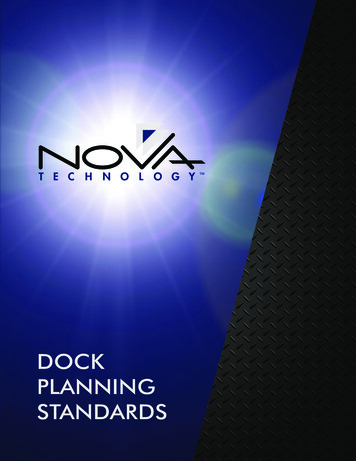
PORT OF BROWNSVILLEBROWNSVILLE, TXOIL DOCK #6EAST PIPE BRIDGETEXASVICINITYPROJECT SITELEGENDPRELIMINARYFOR BIDS ONLYDECEMBER 23, 2021LANIER & ASSOCIATESPORT OF BROWNSVILLEBROWNSVILLETEXASCONSULTING ENGINEERSOIL DOCK #6 - EAST PIPE BRIDGETITLE SHEET, AREA MAP, VICINITY MAPLEGEND & DRAWING INDEXCS1
PRELIMINARYFOR BIDS ONLYDECEMBER 23, 2021LANIER & ASSOCIATESPORT OF BROWNSVILLEBROWNSVILLETEXASCONSULTING ENGINEERSOIL DOCK #6EAST PIPE BRIDGEGENERAL NOTESCS2
PRELIMINARYFOR BIDS ONLYDECEMBER 23, 2021LANIER & ASSOCIATESPORT OF BROWNSVILLEBROWNSVILLETEXASCONSULTING ENGINEERSOIL DOCK #6EAST PIPE BRIDGEOVERALL EXISTING SITE PLANSP1
PRELIMINARYFOR BIDS ONLYDECEMBER 23, 2021LANIER & ASSOCIATESPORT OF BROWNSVILLEBROWNSVILLETEXASCONSULTING ENGINEERSOIL DOCK #6EAST PIPE BRIDGEENLARGED DEMO PLAN & ENLARGED NEW SITE PLANSP2
PRELIMINARYFOR BIDS ONLYDECEMBER 23, 2021LANIER & ASSOCIATESPORT OF BROWNSVILLEBROWNSVILLETEXASCONSULTING ENGINEERSOIL DOCK #6EAST PIPE BRIDGEPILE PLAN & SCHEDULESP3
PRELIMINARYFOR BIDS ONLYDECEMBER 23, 2021LANIER & ASSOCIATESPORT OF BROWNSVILLEBROWNSVILLETEXASCONSULTING ENGINEERSOIL DOCK #6EAST PIPE BRIDGEPLANS & ELEVATIONS1
PRELIMINARYFOR BIDS ONLYDECEMBER 23, 2021LANIER & ASSOCIATESPORT OF BROWNSVILLEBROWNSVILLETEXASCONSULTING ENGINEERSOIL DOCK #6EAST PIPE BRIDGESECTIONSS2
PRELIMINARYFOR BIDS ONLYDECEMBER 23, 2021LANIER & ASSOCIATESPORT OF BROWNSVILLEBROWNSVILLETEXASCONSULTING ENGINEERSOIL DOCK #6EAST PIPE BRIDGESECTIONS & DETAILS - SHT. 1S3
PRELIMINARYFOR BIDS ONLYDECEMBER 23, 2021LANIER & ASSOCIATESPORT OF BROWNSVILLEBROWNSVILLETEXASCONSULTING ENGINEERSOIL DOCK #6EAST PIPE BRIDGESECTIONS AND DETAILS - SHT. 2S4
PRELIMINARYFOR BIDS ONLYDECEMBER 23, 2021LANIER & ASSOCIATESPORT OF BROWNSVILLEBROWNSVILLETEXASCONSULTING ENGINEERSOIL DOCK #6EAST PIPE BRIDGECONNECTION DETAILSS5
PRELIMINARYFOR BIDS ONLYDECEMBER 23, 2021LANIER & ASSOCIATESPORT OF BROWNSVILLEBROWNSVILLETEXASCONSULTING ENGINEERSOIL DOCK #6EAST PIPE BRIDGETXDOT METAL BEAM GUARD FENCES6
PORT OF BROWNSVILLEBROWNSVILLE, TXTECHNICAL SPECIFICATIONSFOROIL DOCK #6 EAST SIDE PIPE BRIDGEPREPARED BY:PH: 504-895-0368WWW.LANIER-ENGINEERS.COMTEXAS FIRM NO. F-2981JOB NUMBER 11769DECEMBER 23, 2021
LANIER JOB NO. 11769DECEMBER 23, 2021PORT OF BROWNSVILLEOIL DOCK #6 EAST PIPE BRIDGEDOCUMENT 00 01 10 - TABLE OF CONTENTSPIP SPECIFICATIONSPIP NUMBERSPECIFICATION NAMEREV.PAGESSTC01015Structural Design CriteriaA52STF05121Anchor Fabrication and Installation into ConcreteA12STI03310Concrete General Notes and Typical DetailsA16STS02360Driven Piles SpecificationA25STS03001Plain and Reinforced Concrete SpecificationA18STS03600Nonshrink Cementitious Grout SpecificationA10STS05120Structural and Miscellaneous Steel Fabrication SpecificationA20STS05130Structural and Miscellaneous Steel Erection SpecificationA14TEXAS DEPARTMENT OF TRANSPORTATION SPECIFICATIONSITEM NUMBERSPECIFICATION NAMEREV.ITEM 504Metal Beam Guard Fence--PAGES4NOTE: The specifications referenced above and included in these documents have been provided by the Owner’sEngineer. Contractor shall request all standards and construction specifications prepared by the Owner. Wherethere is similarity between the specifications listed above and those provided by the Owner, the strictestgovernance shall apply.TABLE OF CONTENTSPage 1
COMPLETE REVISIONApril 2017StructuralPIP STC01015Structural Design Criteria
PURPOSE AND USE OF PROCESS INDUSTRY PRACTICESIn an effort to minimize the cost of process industry facilities, this Practice hasbeen prepared from the technical requirements in the existing standards of majorindustrial users, contractors, or standards organizations. By harmonizing these technicalrequirements into a single set of Practices, administrative, application, and engineeringcosts to both the purchaser and the manufacturer should be reduced. While this Practiceis expected to incorporate the majority of requirements of most users, individualapplications may involve requirements that will be appended to and take precedence overthis Practice. Determinations concerning fitness for purpose and particular matters orapplication of the Practice to particular project or engineering situations should not bemade solely on information contained in these materials. The use of trade names fromtime to time should not be viewed as an expression of preference but rather recognizedas normal usage in the trade. Other brands having the same specifications are equallycorrect and may be substituted for those named. All Practices or guidelines are intendedto be consistent with applicable laws and regulations including OSHA requirements. Tothe extent these Practices or guidelines should conflict with OSHA or other applicablelaws or regulations, such laws or regulations must be followed. Consult an appropriateprofessional before applying or acting on any material contained in or suggested by thePractice.This Practice is subject to revision at any time. Process Industry Practices (PIP), Construction Industry Institute, The University ofTexas at Austin, 3925 West Braker Lane (R4500), Austin, Texas 78759. PIP MemberCompanies and Subscribers may copy this Practice for their internal use. Changes ormodifications of any kind are not permitted within any PIP Practice without the expresswritten authorization of PIP. Authorized Users may attach addenda or overlays to clearlyindicate modifications or exceptions to specific sections of PIP Practices. Authorized Usersmay provide their clients, suppliers and contractors with copies of the Practice solely forAuthorized Users’ purposes. These purposes include but are not limited to the procurementprocess (e.g., as attachments to requests for quotation/ purchase orders or requests forproposals/contracts) and preparation and issue of design engineering deliverables for useon a specific project by Authorized User’s client. PIP’s copyright notices must be clearlyindicated and unequivocally incorporated in documents where an Authorized User desiresto provide any third party with copies of the Practice.PUBLISHING HISTORYDecember 1998IssuedFebruary 2002Technical RevisionApril 2002Editorial RevisionAugust 2004Complete RevisionFebruary 2006Technical CorrectionSeptember 2007Technical CorrectionApril 2017Complete RevisionNot printed with State funds
COMPLETE REVISIONApril 2017StructuralPIP STC01015Structural Design CriteriaTable of Contents1. Scope . 22. References . 22.12.22.32.4Process Industry Practices . 2Industry Codes and Standards . 3Government Regulations . 6Other References . 63. Definitions . 64. Requirements. 74.14.24.34.4Design Loads . 7Load Combinations . 20Structural Design . 43Existing Structures . 50Process Industry PracticesPage 1 of 50
PIP STC01015Structural Design Criteria1.COMPLETE REVISIONApril 2017ScopeThis Practice describes the minimum requirements for the structural design of process industryfacilities at onshore sites.This Practice is intended to be used in conjunction with PIP ARC01015, PIP ARC01016,PIP CVC01015, PIP CVC01017, and PIP CVC01018, as applicable.This Practice does not include design criteria for loads associated with transportation or lifting ofmodular structures.This Practice provides triple references to ASCE/SEI 7-10, IBC 2012, and IBC 2015. Theapplicable code/standard shall be as required by the authority having jurisdiction (AHJ) and asspecified in PIP CVC01017.This Practice references U.S. codes and standards, but it can be applied globally. For projects inother countries, a thorough search of applicable codes and standards is required. Where morestringent than U.S. codes and standards, the local codes and standards shall govern. For projectsin countries without applicable codes and standards, the U.S. codes and standards shall govern.2.ReferencesApplicable parts of the following Practices, industry codes and standards, and references shall beconsidered an integral part of this Practice. The edition in effect on the date of contract awardshall be used, except as otherwise noted. Short titles are used herein where appropriate.2.1Process Industry Practices (PIP)– PIP ARC01015 - Architectural and Building Utilities Design Criteria– PIP ARC01016 - Building Data Sheet– PIP CVC01015 - Civil Design Criteria– PIP CVC01017 - Plant Site Data Sheet– PIP CVC01018 - Project Data Sheet– PIP PCCWE001 - Weighing Systems Design Criteria– PIP PCEWE001 - Weighing Systems Guidelines– PIP REIE686/API RP686 - Recommended Practice for Machinery Installation andInstallation Design– PIP REIE686A - Recommended Practice for Machinery Installation andInstallation Design (Supplement to PIP REIE686/API RP686)– PIP STC01018 - Blast Resistant Building Design Criteria– PIP STE05121 - Application of ASCE Anchorage Design for PetrochemicalFacilities– PIP STE03360 - Heat Exchanger and Horizontal Vessel Foundation Design GuideProcess Industry PracticesPage 2 of 50
PIP STC01015Structural Design Criteria2.2COMPLETE REVISIONApril 2017Industry Codes and Standards American Association of State Highway and Transportation Officials (AASHTO)– AASHTO Standard Specifications for Highway Bridges American Concrete Institute (ACI)– ACI 318-11 - Building Code Requirements for Structural Concrete andCommentary– ACI 318-14 - Building Code Requirements for Structural Concrete andCommentary– ACI 318M-11 - Building Code Requirements for Structural Concrete andCommentary (Metric)– ACI 318M-14 - Building Code Requirements for Structural Concrete andCommentary (Metric)– ACI 350 - Code Requirements for Environmental Engineering Concrete Structuresand Commentary– ACI 350M - Code Requirements for Environmental Engineering ConcreteStructures and Commentary (Metric)– ACI 376 - Code Requirements for Design and Construction of Concrete Structuresfor the Containment of Refrigerated Liquefied Gases and Commentary– ACI 376M - Code Requirements for Design and Construction of ConcreteStructures for the Containment of Refrigerated Liquefied Gases and Commentary(Metric) American Institute of Steel Construction (AISC)– AISC 341 - Seismic Provisions for Structural Steel Buildings– ANSI/AISC 360 - Specification for Structural Steel Buildings American Iron and Steel Institute (AISI)– AISI S100 - North American Specification for the Design of Cold-Formed SteelStructural Members American Petroleum Institute (API)– API Standard 650 - Welded Steel Tanks for Oil Storage American Society of Civil Engineers (ASCE)– ASCE/SEI 7-10 - Minimum Design Loads for Buildings and Other Structures– ASCE/SEI 37-14 - Design Loads on Structures during Construction– Design of Blast-Resistant Buildings in Petrochemical Facilities - Task Committeeon Blast-Resistant Design of the Petrochemical Committee of the Energy Divisionof the American Society of Civil Engineers, 2010– Guidelines for Seismic Evaluation and Design of Petrochemical Facilities - TaskCommittee on Seismic Evaluation and Design of the Petrochemical Committee ofthe Energy Division of the American Society of Civil Engineers, 2011Process Industry PracticesPage 3 of 50
PIP STC01015Structural Design CriteriaCOMPLETE REVISIONApril 2017– Wind Loads for Petrochemical and Other Industrial Facilities - Task Committeeon Wind-Induced Forces of the Petrochemical Committee of the Energy Divisionof the American Society of Civil Engineers, 2011 American Society of Mechanical Engineers (ASME) / Canadian StandardsAssociation (CSA)– ASME A17.1/CSA B44 - Safety Code for Elevators and Escalators ASTM International (ASTM)– ASTM A36/A36M - Standard Specification for Carbon Structural Steel– ASTM A193/A193M - Standard Specification for Alloy-Steel and Stainless SteelBolting for High Temperature or High Pressure Service and Other Special PurposeApplications– ASTM A307 - Standard Specification for Carbon Steel Bolts, Studs,and Threaded Rod 60 000 PSI Tensile Strength– ASTM A354 - Standard Specification for Quenched and Tempered Alloy SteelBolts, Studs, and Other Externally Threaded Fasteners– ASTM A500/A500M - Standard Specification for Cold-Formed Welded andSeamless Carbon Steel Structural Tubing in Rounds and Shapes– ASTM A572/A572M - Standard Specification for High-Strength Low-AlloyColumbium-Vanadium Structural Steel– ASTM A615/A615M - Standard Specification for Deformed and Plain CarbonSteel Bars for Concrete Reinforcement– ASTM A706/A706M - Standard Specification for Deformed and Plain Low-AlloySteel Bars for Concrete Reinforcement– ASTM A992/A992M - Standard Specification for Structural Steel Shapes– ASTM A1064/A1064M - Standard Specification for Carbon-Steel Wire andWelded Wire Reinforcement, Plain and Deformed, for Concrete– ASTM F1554 - Standard Specification for Anchor Bolts, Steel, 36, 55, and 105-ksiYield Strength– ASTM F3125/ASTM F3125M - Standard Specification for High StrengthStructural Bolts, Steel and Alloy Steel, Heat Treated, 120 ksi (830 MPa) and150 ksi (1040 MPa) Minimum Tensile Strength, Inch and Metric Dimensions American Welding Society (AWS)– AWS D1.1/D1.1M - Structural Welding Code - Steel American Wood Council (AWC)– ANSI/AWC NDS - National Design Specification for Wood Construction– NDS Supplement - Design Values for Wood Construction Crane Manufacturers Association of America (CMAA)– CMAA No. 70 - Specifications for Top Running Bridge and Gantry Type MultipleGirder Electric Overhead Traveling CranesProcess Industry PracticesPage 4 of 50
PIP STC01015Structural Design CriteriaCOMPLETE REVISIONApril 2017– CMAA No. 74 - Specifications for Top Running and Under Running Single GirderElectric Traveling Cranes Utilizing Under Running Trolley Hoist International Code Council (ICC)– International Building Code (IBC) 2012– International Building Code (IBC) 2015 National Fire Protection Association (NFPA)– NFPA 59A-01 - Standard for the Production, Storage, and Handling of LiquefiedNatural Gas (LNG)– NFPA 59A-06 - Standard for the Production, Storage, and Handling of LiquefiedNatural Gas (LNG)– NFPA 59A-13 - Standard for the Production, Storage, and Handling of LiquefiedNatural Gas (LNG) Precast/Prestressed Concrete Institute (PCI)– PCI MNL-120 - PCI Design Handbook Research Council on Structural Connections (RCSC)– RCSC Specification for Structural Joints Using High-Strength Bolts Steel Deck Institute (SDI)– SDI C1.0 - Standard for Composite Steel Floor Deck– SDI NC1.0 - Standard for Non-Composite Steel Floor Deck– SDI RD1.0 - Standard for Steel Roof Deck Steel Joist Institute (SJI)– SJI-CJ - Standard Specification for Composite Steel Joists CJ-Series– SJI-K - Standard Specification for Open Web Steel Joists, K-Series– SJI-LH/DLH - Standard Specification for Long Span Joists, LH-Series and DeepLong Span Joists, DLH-Series– SJI-JG - Standard Specification for Joist Girders The Masonry Society (TMS) / American Concrete Institute (ACI) / StructuralEngineering Institute of the American Society of Civil Engineers (SEI/ASCE)– TMS 402/ACI 530/ASCE 5 - Code Requirements for Masonry StructuresProcess Industry PracticesPage 5 of 50
PIP STC01015Structural Design Criteria2.3COMPLETE REVISIONApril 2017Government RegulationsFederal Standards and Instructions of the Occupational Safety and Health Administration(OSHA), including any additional requirements by state or local agencies that havejurisdiction in the state where the project is to be constructed, shall apply. U.S. Department of Labor (DOL), Occupational Safety and Health Administration(OSHA)– OSHA 29 CFR 1910 Subpart D - Walking-Working Surfaces– OSHA 29 CFR 1926 - Safety and Health Regulations for Construction US Department of Transportation (DOT), Pipeline and Hazardous Materials SafetyAdministration (PHMSA)– PHMSA 49 CFR 193 - Liquefied Natural Gas Facilities: Federal Safety Standards2.4Other References Naqvi, D., Wey, E., and O'Rourke, M., Snow Loads on Non-Building Structures,Structures Congress 2012: pp. 1452-1462. Federal Energy Regulatory Commission (FERC), Draft Seismic Design Guidelinesand Data Submittal Requirements for LNG Facilities, January 23, 2007.3.Definitionsauthority having jurisdiction (AHJ): A person who has the delegated authority to determine,mandate, and enforce code requirements established by jurisdictional governing bodies.engineer of record: Purchaser’s authorized representative with overall authority andresponsibility for engineering design, quality, and performance of civil works, structures,foundations, materials, and appurtenances described in contract documents. Engineer of recordshall be licensed as defined by laws of the locality in which the work is to be constructed, and bequalified to practice in the specialty discipline required for the work described in contractdocuments.environmental engineering concrete structures: Concrete structures intended for conveying,storing, or treating water, wastewater, or other liquids and non-hazardous materials such as solidwaste, and for secondary containment of hazardous liquids or solid waste.owner: Party who has authority through ownership, lease, or other legal agreement over thebuildings, structures and foundations to be designed.Process Industry PracticesPage 6 of 50
COMPLETE REVISIONPIP STC01015Structural Design Criteria4.April 2017Requirements4.1Design Loads4.1.1General4.1.1.1 New facilities, buildings, and other structures, including floor slabs andfoundations, shall be designed to resist the minimum loads defined inASCE/SEI 7-10, IBC 2012, or IBC 2015 as applicable, local buildingcodes, this section and the loads defined in PIP CVC01017 andCVC01018.4.1.1.2 In addition to the loads in this section, other loads shall be considered asappropriate. These loads shall include, but are not limited to ice, rain,hydrostatic, dynamic, upset conditions, earth pressure, vehicles,buoyancy, and erection.4.1.1.3 Loads associated with transportation and lifting of modular structuresshall also be considered as appropriate.4.1.1.4 Future loads shall be considered if specified by the owner.4.1.1.5 For existing facilities, actual loads may be used in lieu of the minimumspecified loads.4.1.1.6 Eccentric loads (e.g., piping, platforms), particularly on horizontal andvertical vessels and exchangers, shall be considered. For additionalinformation regarding eccentric loads on horizontal vessels andexchangers, see PIP STE03360.4.1.1.7 Risk Categories1. The owner, AHJ, and project process engineers shall be consulted asapplicable to determine the assignment of Risk Categories forbuildings and other structures for the purpose of applying wind,earthquake, snow, and ice load provisions in accordance withASCE/SEI 7-10, Section 1.5; IBC 2012, Section 1604.5; or IBC 2015,Section 1604.5 as applicable.Comment: For process industry facilities, Risk Category III is themost likely classification because of the presence of toxic,highly toxic, or explosive substances. In some cases, itmay be appropriate to select Risk Category IV. RiskCategory II may be used if the owner can demonstrate tothe satisfaction of the AHJ by a hazard assessment that arelease of the toxic, highly toxic, or explosive substancesis not sufficient to pose a threat to the public. SeeASCE/SEI 7-10, Section 1.5.3 and Table 1.5-1; andASCE/SEI 7-10, Commentary for Chapter 1; for specificdetails.2. Risk Categories for Liquefied Natural Gas (LNG) facilities shall be inaccordance with NFPA 59A-13, Sections 5.4.1 and 5.4.2, asapplicable.Process Industry PracticesPage 7 of 50
COMPLETE REVISIONPIP STC01015Structural Design CriteriaApril 2017Comment: PHMSA 49CFR193, and NFPA 59A-01 and NFPA 59A06, which are referenced by PHMSA 49CFR193, do notspecifically mention Risk Categories (or OccupancyCategories) in their requirements. NFPA 59A-13 uses theterm Occupancy Category which is considered to beequivalent to the term Risk Category used by ASCE/SEI7-10. See Federal Energy Regulatory Commission(FERC), Draft Seismic Design Guidelines and DataSubmittal Requirements for LNG Facilities for additionalguidance on Risk Categories (Occupancy Categories) inconjunction with seismic (earthquake) loads for LNGfacilities.4.1.2Dead Loads (D)4.1.2.1 Dead loads are the actual weight of materials forming the building,structure, foundation, and all permanently attached appurtenances(e.g., lighting, instrumentation, HVAC, sprinkler and deluge systems,fireproofing, insulation).4.1.2.2 Weights of fixed process equipment and machinery, piping, valves,electrical cable trays, and the contents of these items shall also beconsidered as dead loads.4.1.2.3 For this Practice, dead loads are designated by the followingnomenclature:Ds, Df, De, Do, and Dt, where:Ds Structure dead load is the weight of materials forming thestructure (i.e., not the empty weight of process equipment,vessels, tanks, piping, nor cable trays), foundation, soil above thefoundation resisting uplift, and all permanently attachedappurtenances (e.g., lighting, instrumentation, HVAC, sprinklerand deluge systems, fireproofing, and insulation, etc.).Df Erection dead load is the fabricated weight of process equipmentor vessels. See Section 4.1.2.4 for further definition.De Empty dead load is the empty weight of process equipment,vessels, tanks, piping, and cable trays. See Sections 4.1.2.4through 4.1.2.7 for further definition.Do Operating dead load is the empty weight of process equipment,vessels, tanks, piping, and cable trays (De) plus the maximumweight of contents during normal operation. See Sections 4.1.2.4through 4.1.2.8 for further definition.Dt Test dead load is the empty weight of process equipment,vessels, tanks, and/or piping (De) plus the weight of the testmedium contained in the system. See Section 4.1.2.4 for furtherdefinition.Process Industry PracticesPage 8 of 50
COMPLETE REVISIONPIP STC01015Structural Design CriteriaApril 20174.1.2.4 Process Equipment and Vessel Dead Loads1. Erection dead load (Df) for process equipment and vessels is normallythe fabricated weight of the equipment or vessel and is generallytaken from the certified equipment or vessel drawing.2. Empty dead load (De) for process equipment and vessels is the emptyweight of the equipment or vessels, including all attachments, trays,internals, insulation, fireproofing, agitators, piping, ladders, platforms,etc. Empty dead load also includes weight of machinery (e.g., pumps,compressors, turbines, and packaged units).3. Operating dead load (Do) for process equipment and vessels is theempty dead load (De) plus the maximum weight of contents (includingpacking/catalyst) during normal operation.4. Test dead load (Dt) for process equipment and vessels is the emptydead load (De) plus the weight of test medium contained in thesystem. The test medium shall be as specified in the contractdocuments or as specified by the owner. Unless otherwise specified, aminimum specific gravity of 1.0 shall be used for the test medium.Equipment and pipes that may be simultaneously tested shall beincluded. Cleaning load shall be used for test dead load if the cleaningfluid is heavier than the test medium.4.1.2.5 Equipment/Platform Structure Dead Loads1. In addition to primary dead loads for the structural steel, fireproofing,major equipment and large bore piping, dead loads onequipment/platform structures shall be included to account forgrating, checkered plate, concrete decking, guard systems, ladders andcages, small equipment, piping, electrical conduits, lighting and othermiscellaneous items.2. Unless more determinate load information is available and requiresotherwise, dead loads for the following items shall be estimated asfollows:a. Uniformly distributed loads for grating, checkered plate, andconcrete decking (Ds):(1) Grating: 9.1 psf (0.44 kN/m2) for 1-1/4 inches x 3/16 inch (32mm x 5 mm) plain grating(2) Checkered Plate: 11.25 psf (0.54 kN/m2) for 1/4 inch (6 mm)checkered plate(3) Concrete Deck: based upon deck manufacturer’s tables.b. Guard systems and ladders and cages (Ds):(1) Angle Guard Systems with Toe Plate: 15 lbs/ft (0.22 kN/m) ofguard length (L 2 ½ x 2 ½ x ¼).(2) Pipe Guard Systems with Toe Plate: 11 lbs/ft (0.16 kN/m) ofguard length for pipe guard (NPS 1 ½ STD or HSS 1.900 x0.145)Process Industry PracticesPage 9 of 50
COMPLETE REVISIONPIP STC01015Structural Design CriteriaApril 2017(2) Ladders with Cages: 30 lbs/ft (0.44 kN/m) of ladder length(3) Ladders without Cages: 11 lbs/ft (0.16 kN/m) of ladder lengthc. Empty dead load (De) for small equipment, piping, electricalconduits, lighting and other miscellaneous items:For checking uplift and components controlled by minimumloading, a uniformly distributed load of 0 psf (0 kN/m2) to 20 psf(1.0 kN/m2) as determined by engineering judgment for loadcombinations that include wind load or earthquake loadd. Operating dead load (Do) for small equipment, piping, electricalconduits, lighting and other miscellaneous items:A uniformly distributed load of 10 psf (0.5 kN/m2) to 30 psf (1.5kN/m2) as determined by engineering judgment4.1.2.6 Pipe Rack Piping Loads1. Unless more determinate load information is available and requiresotherwise, dead loads for piping on pipe racks shall be estimated asfollows:a. Operating dead load (Do): A uniformly distributed load of 20 psf(1.0 kN/m2) to 60 psf (3.0 kN/m2) as determined by engineeringjudgment for piping, product, valves, fittings, and insulation basedon the average size of piping on each level.Comment: A uniformly distributed load of 40 psf (2.0 kN/m2) isequivalent to NPS 8 (DN 200) STD pipes, full ofwater, at 15-inch (375-mm) spacing.b. Empty dead load (De): For checking uplift and componentscontrolled by minimum loading, 40% to 60% of the estimatedoperating dead load (Do) shall be used as determined byengineering judgment for load combinations that include wind loador earthquake load. Empty dead load shall not be included forunutilized portions of piping levels.c. Test dead load (Dt) is the empty weight of the pipe (De) plus theweight of test medium contained in a set of simultaneously testedpiping systems. The test medium shall be as specified in thecontract documents or as specified by the owner. Unless otherwisespecified, a minimum specific gravity of 1.0 shall be used for thetest medium.2. For any pipe at least two sizes larger than the average pipe size on thepiping level being considered, an additional uniform or concentratedload, including the weight of piping, product, valves, fittings, andinsulation shall be used for dead load not included in the regularuniformly distributed piping loads specified in Section 4.1.2.6.1.a.3. The normal operating weight of vapor and flare pipes, pipes withcommodities significantly lighter than water, and NPS 20 (DN500)and larger pipes shall be considered separately.Process Industry PracticesPage 10 of 50
COMPLETE REVISIONPIP STC01015Structural Design CriteriaApril 2017Comment: The loads for these piping systems can be significantlydifferent than loads determined for other piping and cansignificantly affect the design of the pipe rack, especiallyfor load combinations that include wind load orearthquake load.4. When applying dead loads for piping, consideration shall be given tounsymmetrical loading of the piping levels that can impact theminimum and maximum controlling cases for elements of the piperack and foundations.5. Pipe racks and their foundations shall be designed to support loadsassociated with full utilization of the available space on piping levelsfor operating load combinations.6. Pipe racks and their foundations shall be designed to support anyspecified future piping level expansion.4.1.2.7 Pipe Rack Cable Tray Loads1. Unless more determinate load information is available and requiresotherwise, dead loads for cable trays on pipe racks shall be estimatedas follows:a. Operating dead load (Do): A uniformly distributed dead load of20 psf (1.0 kN/m2) to 40 psf (2.0 kN/m2) per level of cable trays asdetermined by engineering judgment based on the weight of thetrays, the types of cables supported in the trays and the weight ofthose cables loaded to the full (i.e., maximum) capacity that can beplaced in the trays considering electrical code spacingrequirements for the cables.b. Empty dead load (De): For checking uplift and componentscontrolled by minimum loading, a reduced level of cable tray loadthat considers how full the trays may actually be loaded shall beconsidered as the empty dead load for load combinations thatinclude wind load or earthquake load. The tray load for the emptycondition is often significantly less than the full cable traycondition. Empty dead load shall not be included for unutilizedportions of cable tray levels.2. When applying dead loads for cable trays, consideration shall begiven to unsymmetrical loading of the cable tray levels that canimpact the minimum and maximum controlling cases for elements ofthe pipe rack and foundations.3. Pipe racks and their foundations shall be designed to support loadsassociated with full utilization of the available space on cable traylevels for operating load combinations.4. Pipe racks and their foundations shall be designed to support anyspecified future cable tray level expansion.Process Industry PracticesPage 11 of 50
COMPLETE REVISIONPIP STC01015Structural Design CriteriaApril 20174.1.2.8 Ground-Supported Storage Tank Loads1. Dead loads for ground-supported storage tanks are shown in Table 12with the same nomenclature as other dead loads in this Practice forconsistency.2. The individual load components making up the dead loads may haveto be separated for actual use in design in accordance with thefollowing considerations:a. Operating dead load (Do): Operating dead load consists of theweight of the tank shell, roof
Commentary – ACI 318-14 - Building Code Requirements for Structural Concrete and Commentary – ACI 318M-11 - Building Code Requirements for Structural Concrete and Commentary (Metric) – ACI 318M-14 - Building Code Requirements for Structural Concrete and Commentary (Metric) – ACI 350 - Cod