Transcription
Aalborg UniversitetOverview of catastrophic failures of freewheeling diodes in power electronic circuitsWu, Rui; Blaabjerg, Frede; Wang, Huai; Liserre, MarcoPublished in:Microelectronics ReliabilityDOI (link to publication from on date:2013Document VersionAccepted author manuscript, peer reviewed versionLink to publication from Aalborg UniversityCitation for published version (APA):Wu, R., Blaabjerg, F., Wang, H., & Liserre, M. (2013). Overview of catastrophic failures of freewheeling diodes inpower electronic circuits. Microelectronics Reliability, 53(9-11), 3.07.126General rightsCopyright and moral rights for the publications made accessible in the public portal are retained by the authors and/or other copyright ownersand it is a condition of accessing publications that users recognise and abide by the legal requirements associated with these rights.- Users may download and print one copy of any publication from the public portal for the purpose of private study or research.- You may not further distribute the material or use it for any profit-making activity or commercial gain- You may freely distribute the URL identifying the publication in the public portal Take down policyIf you believe that this document breaches copyright please contact us at vbn@aub.aau.dk providing details, and we will remove access tothe work immediately and investigate your claim.Downloaded from vbn.aau.dk on: July 06, 2022
Microelectronics Reliability xxx (2013) xxx–xxxContents lists available at ScienceDirectMicroelectronics Reliabilityjournal homepage: www.elsevier.com/locate/microrelOverview of catastrophic failures of freewheeling diodesin power electronic circuitsR. Wu , F. Blaabjerg, H. Wang, M. LiserreCentre of Reliable Power Electronics (CORPE), Department of Energy Technology, Aalborg University, Pontoppidanstraede 101, 9220 Aalborg, Denmarka r t i c l ei n f oArticle history:Received 24 May 2013Received in revised form 14 July 2013Accepted 20 July 2013Available online xxxxa b s t r a c tEmerging applications (e.g. electric vehicles, renewable energy systems, more electric aircrafts, etc.) havebrought more stringent reliability constrains into power electronic products because of safety requirements and maintenance cost issues. To improve the reliability of power electronics, better understandingof failure modes and failure mechanisms of reliability–critical components in power electronic circuitsare needed. Many efforts have been devoted to the reduction of IGBT failures, while the study on thefailures of freewheeling diodes is less impressive. It is of importance to investigate the catastrophicfailures of freewheeling diodes as they could induce the malfunction of other components and eventuallythe whole power electronic circuits. This paper presents an overview of those catastrophic failures andgives examples of the corresponding consequences to the circuits.Ó 2013 Elsevier Ltd. All rights reserved.1. IntroductionPower electronics plays an important role in energy conversionapplications, such as motor drives, utility interfaces withrenewable energy sources, power transmission (e.g. high voltagedirect current systems, and flexible alternating current transmission systems), electric or hybrid electric vehicles. Therefore, thereliability of power electronics becomes more and more vital,and should draw more attention [1]. According to a survey, semiconductor failures and soldering joints failures in power devicestake up 34% of power electronic system failures [2]. Another surveyshows that around 38% of faults in variable speed ac drives are dueto failures of power semiconductor devices [3]. A recent questionnaire on industrial power electronic systems also shows that theresponders regard power electronic reliability as an important issue, and 31% of responders selected power semiconductor devicesas the most fragile component in their applications [4]. Therefore,it demands a better understanding of failure mechanisms of powersemiconductor devices so as to reduce their failure rates.Diodes and Insulated Gate Bipolar Transistors (IGBTs) are twokinds of reliability–critical power semiconductor devices widelyused in power electronic circuits [1]. Power diodes are usually assumed to have outstanding ruggedness performance. However,freewheeling diodes fail under various circumstances, especiallyduring the turn-on transition of IGBTs in high switching frequencyapplications. The freewheeling diodes slow down the switchingspeed of the IGBTs due to severe stresses induced by the reverserecovery process. Therefore, it is worth to investigate the failures Corresponding author. Tel.: 45 2963 2067; fax: 45 9815 1411.E-mail address: rwu@et.aau.dk (R. Wu).of freewheeling diodes and exploring the solutions to improvethe reliability of both freewheeling diodes and IGBTs.Diode failures can generally be classified as catastrophic failuresand wear out failures. Diode wear out failures are mainly inducedby accumulated degradation with time, while catastrophic failuresare triggered by single-event overstress, such as overvoltage,overcurrent, overheat. Prognostics and Health Management(PHM) method can monitor the degradation of diodes and estimatewear out failures [5]. However, PHM is not applicable for catastrophic failures, which are more difficult to be predicted.Several overview papers cover the topic on diode failures. In [6],Rahimo et al. discuss the major reverse recovery failure modes offreewheeling diode in IGBT applications. While it only focuses onsnappy recovery and dynamic avalanching, no static failure is mentioned. In [7], Ciappa gives a comprehensive overview on the wearout failure mechanisms of power semiconductor devices, such asbond wire fatigue, aluminum reconstruction, substrate cracking,interconnections corrosion, and solder fatigue and voids. Howeverit mainly focuses on IGBT, and freewheeling diodes catastrophicfailures are not discussed. Therefore, a detailed and comprehensivereview on diode catastrophic failures is still lack in the prior-artliteratures. Moreover, it is also worth to investigate the influenceof freewheeling diode failures to IGBT operations in power electronic converters.The aim of this paper is to provide a review of the key behaviorsof diode catastrophic failure due to overstresses and the corresponding influence to IGBTs in power electronic circuits. Section 2classifies the types of freewheeling diode catastrophic failures. Section 3 summarizes the catastrophic failures of diode in terms offailure mode and failure mechanism. Section 4 investigates theinfluence of freewheeling diode failures to IGBT operations in0026-2714/ - see front matter Ó 2013 Elsevier Ltd. All rights .07.126Please cite this article in press as: Wu R et al. Overview of catastrophic failures of freewheeling diodes in power electronic circuits. Microelectron Reliab(2013), http://dx.doi.org/10.1016/j.microrel.2013.07.126
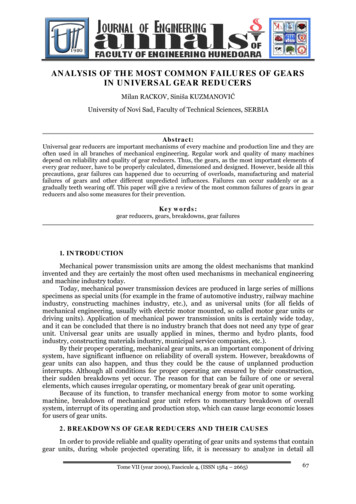
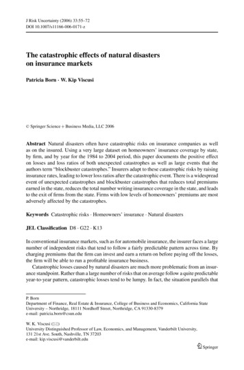
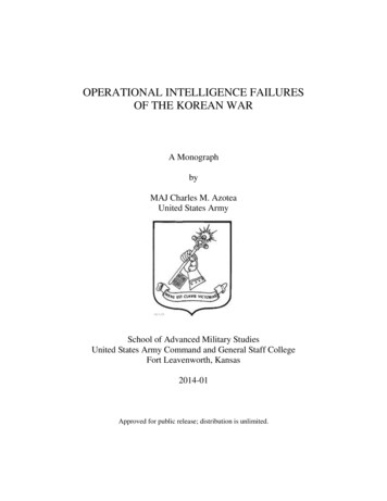
2R. Wu et al. / Microelectronics Reliability xxx (2013) xxx–xxxpower electronic converters, followed by the conclusion inSection 5.IIF2. Classification of failure modes of freewheeling diodesThe catastrophic failure modes of freewheeling diodes can beclassified into open-circuit failures and short-circuit failures. Normally open-circuit failures are considered not fatal to converters,since the converter can operate with lower quality of output [8].On the contrary, short-circuit failures are more fatal to converters,as the uncontrolled short-circuit current may destroy the activeswitching devices (e.g. IGBTs) or other components in the circuit.Fig. 1 shows the typical open-circuit failures and short-circuitfailures of freewheeling diodes.2.1. Open-circuit failuresFreewheeling diode open-circuit failures are generally due tomechanical causes. Open-circuit failure mode can happen becauseof external disconnections due to vibration, or internally by bondwire lift-off or rupture after temperature swings or high short-circuitcurrent.2.2. Short-circuit failuresShort-circuit is also a common failure mode of freewheelingdiodes in power electronic circuits. Failures can happen duringreverse blocking state as well as the reverse recovery transition.Fig. 2 shows the definition of reverse and forward voltage fordiodes [9]. There are five major failure mechanisms as shown inFig. 1, which will be discussed in next section.3. Major failure mechanisms of freewheeling diodes3.1. Open-circuit mechanismsSimilar to IGBTs, diode open-circuit will not be initially fatal tothe converter, but may result in secondary failures of other devicesin a power electronic circuit due to interaction among them.The mechanism is similar to that of IGBTs. Bond wire lift-offfailure can happen after short-circuit, caused by high temperaturefatigue and the mismatch of Coefficients of Thermal Expansion(CTEs) between Silicon and Aluminum. Crack may also be initiatedat the periphery of the bonding interface, and the bond wire finallylifts-off when crack propagates to the weaker central bonding area.Central bond wires normally fail at first, and then the survivorbond wires follow [10]. Bond wire rupture is usually slower thanlift-off mechanism and usually observed after long power cyclingtests or long time operation.3.2. Short-circuit mechanismsThe short-circuit failures of freewheeling diode could lead topotential destruction to the relevant IGBTs, and other components,as it induces uncontrolled high current to the circuit. The failureDiode failure behaviorOpen-circuitBond wireBond wire Static highlifted off due rupture aftervoltageto temperature short-circuit breakdownswingsShort-circuitRising of Snappyleakage recoverycurrentReverserecoverydynamicavalancheHigh powerdissipationFig. 1. Overview of freewheeling diodes catastrophic failures.VVRVFIRFig. 2. Definition of reverse and forward voltage of diodes.mechanisms can be static high voltage breakdown, leakage currentrising, snappy recovery, dynamic avalanche during reverserecovery, as well as high temperature due to the power dissipationand so on.3.2.1. Static high voltage breakdownHigh reverse voltage can cause diodes static avalanche. Withreverse voltage reaching first static avalanche point, the currentrises with positive slope, while no permanent failure happens. Ifthe voltage reaches the second avalanche point, there will be aNegative Differential Resistance (NDR), which will lead to the current filament and a quick short-circuit. Detailed numerical simulations are carried for a rated 3.3 kV/1 kA diode, and the results areshown in Fig. 3 [11]. Another research reveals metallizationbetween copper and silicon can also lead to diode electrical breakdown [12]. It is also revealed that the avalanche capability isstrongly dependent on the initial breakdown location and the edgetermination design by numerical simulation and experiments, andthe common failure locations are near the chip’s edge and the bondwires [13]. Since operating voltage of freewheeling diodes isnormally much lower than rated voltage, static high voltage breakdown is not common in nowadays applications.3.2.2. Rising of leakage currentThe leakage current of power diodes is usually very low, but itincreases with voltage and temperature. The value is roughlydoubled for every 10 C raise of temperature. This effect is moreobvious for gold-diffusion diodes, which may be thermally destroyed at high temperature [9].With operating voltage and temperature above the ratingparameters, leakage current increases dramatically and the diodesfail into short circuit at the chip’s peripheral surface [14,15]. Experiments show that the diodes operation temperature can beincreased without risks of failure by improving the junction edgecurrent control, like a junction passivation process [16,17]. A further research reveals the mechanism is junction carrier avalanchemultiplication, and the weak spots are near the chips’ edge [18].The leakage current rising can also be due to repetitive electrostatic discharge [19]. Since short-circuit failures during freewheeling diode reverse status can damage IGBT and circuit quickly, it iscritical to prevent this event.3.2.3. Snappy recoveryFreewheeling diodes are prone to fail easily during reverserecovery process because of snappy recovery. The behavior ofsnappy recovery is shown in Fig. 4, in which a steep decline inthe current is observed after the reverse recovery current reachesthe peak value. The main reason is the sudden disappearance ofthe remaining carriers at the end of the recovery process. Due tohigh di/dt and stray inductance in the circuit, high voltage spikescan appear and damage the diode.Please cite this article in press as: Wu R et al. Overview of catastrophic failures of freewheeling diodes in power electronic circuits. Microelectron Reliab(2013), http://dx.doi.org/10.1016/j.microrel.2013.07.126
3R. Wu et al. / Microelectronics Reliability xxx (2013) xxx–xxx-5-4-3-2-12 (2740V)001 (1500V)4 (4000V)5 (4770V)6 (4180V Second Avalanche)-5000J (Amps/cm )*102-13 (2870V First Avalanche)-4500-4000-3500-3000-25000-22-1000J (Amps/cm2 )-2000-4000-4-5000-60007-7000V (volts)V (volts)*10-3-3000-5-6-80003-7Fig. 3. First and second static avalanche breakdown of a 1700 V rated power diode [11].tstf0.2 I rrmI rrmFig. 4. Current characteristics of snappy reverse recovery behavior [9].It has been validated that both reverse recovery charge andtime increase with diode effective contact area, and snappyrecovery is clearly observed for larger area in numerical simulationand experiments [20]. Thus special attention should be paid tochoose the diode size for avoiding diode failures. H irradiationhas been proposed to obtain trade-off between diodes switchingspeed and softness, which can avoid snappy recovery, validatedby comprehensive experiments and numerical investigations[21–23]. A new design procedure of freewheeling diodes basedon measurement and simulation is also proposed to improve thereverse recovery softness [24]. Controlled Injection of BacksideHoles (CIBH) diodes are also proposed to increase the soft reverserecovery behavior [25]. However, it is still a critical point to avoidsnappy recovery when designing freewheeling diodes.3.2.4. Reverse recovery dynamic avalancheDynamic avalanching occurs at high di/dt switching speeds, asshown in Fig. 5. Dynamic avalanching can result in the generationof a hot spot in the silicon die itself due to non-uniform currentcrowding which leads to the destruction of the device. The causesof these hot spots can range from process to material variations ina single diode silicon chip [26].Impact ionization near N-N junction is considered as the mainreason for the failure. It leads to the negative differential resistanceand current filament, finally a thermal runaway [27–30]. Thisprocess called Egawa effect [26] is very similar to the secondbreakdown in bipolar transistors. Local heating and explosion atthe corner of anode is observed even the reverse voltage is lowerthan static breakdown voltage [31]. A detailed study of dynamicalbehavior of the plasma layer also explains this reverse recoveryfailure [32,33]. To avoid the second current bump observed duringreverse recovery failure, a merged P-i-N Schottky diode is proposedto replace conventional P-i-N freewheeling diode [34]. It showsFig. 5. Freewheeling diode reverse-recovery failure with IGBT short circuit failure[6].Fig. 6. Operation of a single phase inverter under different failure conditions – rreverse recovery transition, s reverse state, t load short-circuit.deep N emitter and wide n-base can improve the dynamic avalanche characteristic in 2D simulations [35,36]. It is also provedCIBH diode can prevent the filaments in N-N junction by 2Dnumerical simulations [33]. An improved impact-ionization modelis proposed to simulate high electrical fields in diodes [37]. Electrothermal simulations show that thermal-induced filament can leadto destructive thermal runway and it is sensitive to contactsthermal resistance [38]. There could be further work to improveboth die structure and thermal performance.3.2.5. High power dissipationWhen the diode forward current is high and temperature is rising, the forward voltage will increase. If the forward voltagePlease cite this article in press as: Wu R et al. Overview of catastrophic failures of freewheeling diodes in power electronic circuits. Microelectron Reliab(2013), http://dx.doi.org/10.1016/j.microrel.2013.07.126
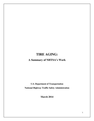
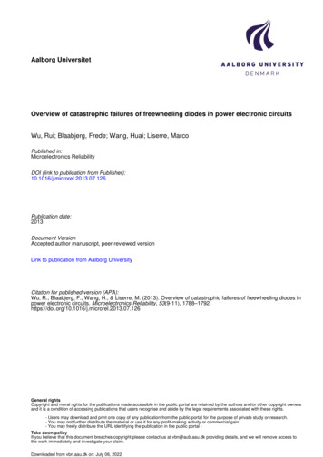
4R. Wu et al. / Microelectronics Reliability xxx (2013) xxx–xxx800AD3 shortcircuit failure400A100A80AiT10A800VvT1400V20A0V0A015V10VT2 and T3on-state5V0V7.98iT160AvT37.998.00102030t[ns]40T1 and T4on-state8.018.028.038.048.05t[ms] 8.06Fig. 7. PSpice simulation waveforms of IGBTs after D3 short circuit in reverse state.exceeds a specified limit value, the overload high power dissipation may fatally damage the silicon die [9].4. Influence of freewheeling diode failures on the operations ofIGBTs in power electronic circuitsFig. 6 shows a single phase inverter consisting of IGBTs (T1 T4)diodes (D1 D4), and stray inductance Ls (which may lead vitalstress to device).The operation of the inverter is as follows: initially, T2 and T3 areon, the current iL flows through the load, then T2 and T3 are turnedoff and T1 and T4 are switched on after a certain period of deadtime. Because the load determines the direction of the current flow,the current will flow through the diodes D1 and D4 back to the voltage source. After iL decreases to zero and to the negative, thecurrent will flow through T1 and T4.There are three typical failure behaviors:(a) When the current is commutating from diode to IGBT, thefreewheeling diode reverse recovery failure may lead to anIGBT short-circuit failure, as shown by r in Fig. 6.(b) When IGBTs T1 and T4 are on, and the current iL flowsthrough the load, reverse diode D3 fails into the short-circuit,the short-circuit current between V and V may damage T1fast, as shown s in Fig. 6.(c) When current is flowing through D1 and D4, a load short circuit will cause overstress of the diodes and IGBTs (symbolized as t – closing the switch S1 in Fig. 6). As the currentflowing through D1 and D4 will be commutated to T1 andT4 rapidly, short-circuit current on IGBTs will be larger.During the transient, both the high reverse recovery currentand the voltage may produce large energy dissipation anddamage the diode. However, the IGBT may also fail first ifthe peak voltage is over the rated voltage [39].As an example, Fig. 7 shows the simulation results of thescenario s in which D3 is short during the conduction of T1. Itcould subsequently induce the failure of T1 due to its increasedcurrent stress as shown in Fig. 7.5. ConclusionsThe typical failure modes and failure mechanisms of freewheeling diodes due to over stresses are overviewed in this paper. Initialshort-circuit failures may lead to open-circuit finally. Short-circuitfailures can happen at five typical occasions.The influence of the freewheeling diode failures to IGBT failuresis also investigated on the circuit level. The associated behaviors ofthe IGBTs are also briefly described.The overview in this paper could be useful for further work inthe following areas: correlations between IGBT and diode failures;improvements of diode performance due to failure mechanisms;effective protection circuits dealing with different catastrophicfailures; fault tolerant design coping with freewheeling diodecatastrophic failures; better models of failure mechanisms; bettermodels and tests of devices beyond the specific rating.References[1] Wang H, Liserre M, Blaabjerg F. Toward reliable power electronics–challenges,design tools and opportunities. In: IEEE Industrial Electronics Magazine, vol. 7,June 2013. p. 17-26.[2] Wolfgang E. Examples for failures in power electronics systems. In: Presentedat ECPE tutorial on reliability power electronic system, Nuremberg, Germany;April 2007.[3] Fuchs FW. Some diagnosis methods for voltage source inverters in variablespeed drives with induction machines—A survey. In: Proceedings of IEEEindustrial electronics society annual conference; 2003. p. 1378–1385.[4] Yang S, Bryant AT, Mawby PA, Xiang D, Ran L, Tavner P. An industry-basedsurvey of reliability in power electronic converters. IEEE Trans Ind Appl2011;47(3):1441–51.[5] Vichare NM, Pecht MG. Prognostics and health management of electronics.IEEE Trans Compon Packag Technol 2006;29(1):222–9.[6] Rahimo MT, Shammas NYA. Freewheeling diode reverse-recovery failuremodes in IGBT applications. IEEE Trans Ind Appl 2001;37(2):661–70.[7] Ciappa M. Selected failure mechanisms of modern power modules.Microelectron Reliab 2002;42(4–5):653–67.[8] Swamy M, Rossiter S. Typical problems encountered with variable frequencydrives in the industry. In: Proc Ind Appl Soc Ann Meet; October 1993. p. 503–10.[9] Wintrich A, Nicolai U, Tursky W, Reimann T. Application manual powersemiconductors. ISLE Verlag, ISBN: 978-3-938843-66-6; 2011. p. 30–6.[10] Ciappa M., Wolfgang F. Lifetime prediction of IGBT modules for tractionapplications. In: Proceedings of 38th annual 2000 IEEE international reliabilityphysics, symposium; 2000. p. 210–6.[11] Huang AQ, Temple V, Liu Y, Li Y. Analysis of the turn-off failure mechanism ofsilicon power diode. Solid-State Electron 2003;47(4):727–39.[12] Baumann J, Kaufmann Ch, Rennau M, Werner Th, Gessner T. Investigation ofcopper metallization induced failure of diode structures with and without abarrier layer. Microelectron. Eng. 1997;33(1–4):283–91.[13] Kim SS, Oh KH, et al. Degradation of avalanche ruggedness of power diodes bythermally induced local breakdown. In: Proceedings of 37th IEEE annualpower electronics specialists conference; June 2006. p. 1–5.[14] Obreja VVN, Codreanu C, Nuttall KI, Buiu O. Reverse current instability ofpower silicon diodes (thyristors) at high temperature and the junction surfaceleakage current. In: Proceedings of the IEEE international symposium onindustrial electronics; June 2005. p. 417–22.[15] Obreja VVN, Podaru C, Manea E, Obreja A, Svasta P. Failure analysis of diode(thyristor) dice from power semiconductor modules after operation above themaximum specified temperature. In: Proceedings of 1st electronics systemintegration technology conference; 2007. p. 1230–5.[16] Obreja VVN. On the reliability of power silicon rectifier diodes above themaximum permissible operation junction temperature. In: Proceedings of IEEEinternational symposium on industrial electronics; July 2006. p. 835–40.[17] Obreja VVN. On the maximum permissible working voltage of commercialpower silicon diodes and thyristors. In: Proceeding of IEEE internationalsymposium on industrial, electronics; June 2007. p. 401–6.[18] Obreja VVN, Codreanu C, Poenar D, Buiu O. Edge current induced failure ofsemiconductor PN junction during operation in the breakdown region ofelectrical characteristic. Microelectron. Reliab. 2011;51(3):536–42.[19] Diatta M, Tremouilles D, Bouyssou E, Perdreau R, Anceau C, Bafleur M.Understanding the failure mechanisms of protection diodes during systemlevel ESD: toward repetitive stresses robustness. IEEE Trans Electron Devices2012;59(1):108–13.[20] Rahimo MT, Shammas NYA. Design considerations of the diode effective areawith regard to the reverse recovery performance. Microelectron J 1999;30(6):499–503.Please cite this article in press as: Wu R et al. Overview of catastrophic failures of freewheeling diodes in power electronic circuits. Microelectron Reliab(2013), http://dx.doi.org/10.1016/j.microrel.2013.07.126
R. Wu et al. / Microelectronics Reliability xxx (2013) xxx–xxx[21] Cova P, Menozzi R, Portesine M. Experimental and numerical study of therecovery softness and overvoltage dependence on p-i-n diode design.Microelectron J 2006;37(5):409–16.[22] Cova P, Menozzi R, Portesine M. Power p-i-n diodes for snubberlessapplication: H irradiation for soft and reliable reverse recovery.Microelectron Reliab 2003;43(1):81–7.[23] Cova P, Menozzi R, Portesine M, Bianconi M, Gombia E, Mosca R. Experimentaland numerical study of H irradiated p-i-n diodes for snubberless applications.Solid-State Electron 2005;49(2):183–91.[24] Bertoluzza F, Cova P, Delmonte N, et al. Coupled measurement-simulationprocedure for very high power fast recovery – soft behavior diode design andtesting. Microelectron Reliab 2010;50(9–11):1720–4.[25] Felsl HP, Pfaffenlehner M, et al. The CIBH diode – great improvement forruggedness and softness of high voltage diodes. In: Proceedings of 20thinternational symposium on power semiconductor devices and IC’s; May2008. p. 173–6.[26] Egawa H. Avalanche characteristics and failure mechanism of high voltagediodes. IEEE Trans Electron Devices 1966;13(11):754–8.[27] Domeij M, Breitholtz B, Hillkirk LM, Linnros J, Ostling M. Dynamic avalanche in3.3-kV Si power diodes. IEEE Trans Electron Devices 1999;46(4):781–6.[28] Oetjen J, Jungblut R, Kuhlmann U, Arkenau J, Sittig R. Current filamentation inbipolar power devices during dynamic avalanche breakdown. Solid-StateElectron 2000;44(1):117–23.[29] Lutz J, Scheuermann U, Schlangenotto H, de Doncker R. Semiconductor powerdevices. Springer Verlag; 2011. ISBN: 3642111246.[30] Domeij M, Breitholtz B, et al. Avalanche injection in high voltage Si P-i-Ndiodes measurements and device simulations. In: Proceedings of 1997 IEEEinternational symposium on power semiconductor devices and IC’s; May1997. p. 125–8.5[31] Tomomatsu Y, Suekawa E, Enjyoji T, et al. An analysis and improvement ofdestruction immunity during reverse recovery for high voltage planar diodesunder high dIrr/dt condition. In: Proceedings of 8th international symposiumon power semiconductor devices and ICs; May 1996. p. 353–6.[32] Baburske R, Heinze B, Lutz J, Niedernostheide F. Charge-carrier plasmadynamics during the reverse-recovery period in p -n–n diodes. IEEE TransElectron Devices 2008;55(8):2164–72.[33] Baburske R, Heinze B, Niedernostheide F, et al. On the formation of stationarydestructive cathode-side filaments in p -n–n diodes. In: Proceedings of 21stinternational symposium on power semiconductor devices & IC’s; June 2009.p. 41–4.[34] Mulay A, Trivedi M, Shenai K. Dynamic avalanching considerations inoptimization of reverse conducting diode in IGBT modules. In: Proceedingsof the 1998 bipolar/BiCMOS circuits and technology meeting; September1998. p. 195–8.[35] Domeij M, Breitholtz B, et al. Stable dynamic avalanche in Si power diodes.Appl Phys Lett 1999;74(21):3170–2.[36] Domeij M, Lutz J, Silber D. On the destruction limit of Si power diodes duringreverse recovery with dynamic avalanche. IEEE Trans Electron Devices2003;50(2):486–93.[37] Pan Z, Holland S, et al. Improved impact-ionization modelling and validation withpn-junction diodes. In: Proceedings of 2010 international conference onsimulation of semiconductor processes and devices; September 2010. p. 287–90.[38] Milady S, Silber D, Niedernostheide F-J, Felsl HP. Different types of avalancheinduced moving current filaments under the influence of dopinginhomogeneities. Microelectron J 2008;39(6):857–67.[39] Lutz J, Dobler R, Mari J, Menzel M. Short circuit III in high power IGBTs. In:Proceedings of 13th European conference on power electronics andapplications; September 2009. p. 1–8.Please cite this article in press as: Wu R et al. Overview of catastrophic failures of freewheeling diodes in power electronic circuits. Microelectron Reliab(2013), http://dx.doi.org/10.1016/j.microrel.2013.07.126
3.2.3. Snappy recovery Freewheeling diodes are prone to fail easily during reverse recovery process because of snappy recovery. The behavior of snappy recovery is shown in Fig. 4, in which a steep decline in the current is observed after the reverse recovery current reaches the peak value. The main reason is the sudden disappearance of