Transcription
Installation Instructions1769-L32E, 1769-L35E CompactLogix ControllerCatalog Numbers 1769-L32E, 1769-L35ETopicPageAbout This Publication2Important User Information3North American Hazardous Location Approval4Environment and Enclosure5Before You Begin6Prevent Electrostatic Discharge7Connect the 1769-BA Battery7Install a 1784-CF64 or 1784-CF128 Industrial CompactFlash Card(optional)9Assemble the System9Mount the System11Make RS-232 Connections to the Controller15Make Ethernet Connections to the Controller18Load the Controller Firmware25Select the Controller’s Operating Mode30Make Ethernet Connections to the Controller18Load the Controller Firmware25Select the Controller’s Operating Mode30Controller Status Indicators31RS-232 Serial Port Status Indicators (Channel 0 and 1)33Publication 1769-IN020-C-EN-P - July 2007
2 1769-L32E, 1769-L35E CompactLogix ControllerTopicPageCompactFlash Card Status Indicator33Module Status (MS) indicator34Additional Resources39About This PublicationUse this document as a guide to install the CompactLogix controller.Publication 1769-IN020-C-EN-P - July 2007
1769-L32E, 1769-L35E CompactLogix Controller 3Important User InformationSolid state equipment has operational characteristics differing from those of electromechanicalequipment. Safety Guidelines for the Application, Installation and Maintenance of Solid State Controls(publication SGI-1.1 available from your local Rockwell Automation sales office or online athttp://literature.rockwellautomation.com) describes some important differences between solid stateequipment and hard-wired electromechanical devices. Because of this difference, and also because ofthe wide variety of uses for solid state equipment, all persons responsible for applying this equipmentmust satisfy themselves that each intended application of this equipment is acceptable.In no event will Rockwell Automation, Inc. be responsible or liable for indirect or consequential damagesresulting from the use or application of this equipment.The examples and diagrams in this manual are included solely for illustrative purposes. Because of themany variables and requirements associated with any particular installation, Rockwell Automation, Inc.cannot assume responsibility or liability for actual use based on the examples and diagrams.No patent liability is assumed by Rockwell Automation, Inc. with respect to use of information, circuits,equipment, or software described in this manual.Reproduction of the contents of this manual, in whole or in part, without written permission of RockwellAutomation, Inc., is prohibited.Throughout this manual, when necessary, we use notes to make you aware of safety considerations.WARNINGIMPORTANTATTENTIONIdentifies information about practices or circumstances that can cause an explosion ina hazardous environment, which may lead to personal injury or death, propertydamage, or economic loss.Identifies information that is critical for successful application and understanding ofthe product.Identifies information about practices or circumstances that can lead to personalinjury or death, property damage, or economic loss. Attentions help you to identify ahazard, avoid a hazard and recognize the consequences.SHOCK HAZARDLabels may be on or inside the equipment, for example, a drive or motor, to alertpeople that dangerous voltage may be present.BURN HAZARDLabels may be on or inside the equipment, for example, a drive or motor, to alertpeople that surfaces may reach dangerous temperatures.Publication 1769-IN020-C-EN-P - July 2007
4 1769-L32E, 1769-L35E CompactLogix ControllerNorth American Hazardous Location ApprovalThe following information applies whenoperating this equipment in hazardouslocations.Informations sur l'utilisation de cet équipement enenvironnements dangereux.Products marked “CL I, DIV 2, GP A, B, C, D” aresuitable for use in Class I Division 2 Groups A, B,C, D, Hazardous Locations and nonhazardouslocations only. Each product is supplied withmarkings on the rating nameplate indicating thehazardous location temperature code. Whencombining products within a system, the mostadverse temperature code (lowest “T” number)may be used to help determine the overalltemperature code of the system. Combinationsof equipment in your system are subject toinvestigation by the local Authority HavingJurisdiction at the time of installation.Les produits marqués “CL I, DIV 2, GP A, B, C, D” neconviennent qu'à une utilisation en environnementsde Classe I Division 2 Groupes A, B, C, D dangereuxet non dangereux. Chaque produit est livré avec desmarquages sur sa plaque d'identification quiindiquent le code de température pour lesenvironnements dangereux. Lorsque plusieursproduits sont combinés dans un système, le code detempérature le plus défavorable (code detempérature le plus faible) peut être utilisé pourdéterminer le code de température global dusystème. Les combinaisons d'équipements dans lesystème sont sujettes à inspection par les autoritéslocales qualifiées au moment de l'installation.EXPLOSION HAZARDWARNINGAVERTISSEMENTRISQUE D'EXPLOSIONDo not disconnect equipmentunless power has beenremoved or the area is knownto be nonhazardous.Couper le courant ou s'assurerque l'environnement est classénon dangereux avant dedébrancher l'équipement.Do not disconnectconnections to thisequipment unless power hasbeen removed or the area isknown to be nonhazardous.Secure any externalconnections that mate to thisequipment by using screws,sliding latches, threadedconnectors, or other meansprovided with this product.Couper le courant ou s'assurerque l'environnement est classénon dangereux avant dedébrancher les connecteurs.Fixer tous les connecteursexternes reliés à cetéquipement à l'aide de vis,loquets coulissants,connecteurs filetés ou autresmoyens fournis avec ce produit.Substitution of componentsmay impair suitability forClass I, Division 2.If this product containsbatteries, they must only bechanged in an area known tobe nonhazardous.Publication 1769-IN020-C-EN-P - July 2007La substitution de composantspeut rendre cet équipementinadapté à une utilisation enenvironnement de Classe I,Division 2.S'assurer que l'environnementest classé non dangereux avantde changer les piles.
1769-L32E, 1769-L35E CompactLogix Controller 5Environment and EnclosureATTENTIONThis equipment is intended for use in a Pollution Degree 2 industrial environment, inovervoltage Category II applications (as defined in IEC publication 60664-1), at altitudesup to 2000 meters (6562 feet) without derating.This equipment is considered Group 1, Class A industrial equipment according toIEC/CISPR Publication 11. Without appropriate precautions, there may be potentialdifficulties ensuring electromagnetic compatibility in other environments due toconducted as well as radiated disturbance.This equipment is supplied as open-type equipment. It must be mounted within anenclosure that is suitably designed for those specific environmental conditions that willbe present and appropriately designed to prevent personal injury resulting fromaccessibility to live parts. The enclosure must have suitable flame-retardant properties toprevent or minimize the spread of flame, complying with a flame spread rating of 5VA, V2,V1, V0 (or equivalent) if non-metallic. The interior of the enclosure must be accessible onlyby the use of a tool. Subsequent sections of this publication may contain additionalinformation regarding specific enclosure type ratings that are required to comply withcertain product safety certifications.In addition to this publication, see: Industrial Automation Wiring and Grounding Guidelines, publication 1770-4.1, foradditional installation requirements. NEMA Standards publication 250 and IEC publication 60529, as applicable, forexplanations of the degrees of protection provided by different types of enclosure.Publication 1769-IN020-C-EN-P - July 2007
6 1769-L32E, 1769-L35E CompactLogix ControllerBefore You BeginConsider the following when planning your CompactLogix system: The CompactLogix controller is always the leftmost module inthe system. The controller must be located within four modules of thesystem power supply. Some I/O modules may be located upto eight modules away from the power supply. See thedocumentation for your 1769 I/O modules for details. The 1769-L32E and 1769-L35E controllers support as many as16 I/O modules in a maximum of 3 I/O banks with 2expansion cables. Each I/O bank requires its own power supply. Only one controller can be used in a CompactLogix system. A 1769-ECR right end cap or 1769-ECL left end cap is requiredto terminate the end of the communication bus.Parts ListThese components ship with the controller.ComponentDescription1769-BA batteryImportant: The 1769-BA battery is the only battery you can usewith the 1769-L32E and 1769-L35E controllers.1747-KY controller keyYou may also use these components with the controller.If you want toThen use this componentConnect a device to the RS 232 port1756-CP3 or 1747-CP3 serial cableConnect a device to the EtherNet/IP portstandard Ethernet cable with RJ-45 connectorAdd nonvolatile memory1784-CF64 or 1784-CF128 Industrial CompactFlash cardPublication 1769-IN020-C-EN-P - July 2007
1769-L32E, 1769-L35E CompactLogix Controller 7Prevent Electrostatic DischargeFollow these guidelines to prevent electrostatic damage.ATTENTIONThis equipment is sensitive to electrostatic discharge, which can cause internaldamage and affect normal operation. Follow these guidelines when you handlethis equipment: Touch a grounded object to discharge potential static. Wear an approved grounding wriststrap. Do not touch connectors or pins on component boards. Do not touch circuit components inside the equipment. Use a static-safe workstation, if available. Store the equipment in appropriate static-safe packaging when not in use.Connect the 1769-BA BatteryThe controller is shipped with the 1769-BA battery packed separately.To connect the battery, follow this procedure.ATTENTIONWARNINGThe 1769-BA battery is the only battery you can use with the 1769-L32E and 1769-L35Econtrollers. The 1747-BA battery is not compatible with the 1769-L32E and 1769-L35Econtrollers and may cause problems.When you connect or disconnect the battery, an electrical arc can occur. This could causean explosion in hazardous location installations. Be sure that power is removed or the areais nonhazardous before proceeding.For safety information on the handling of lithium batteries, including handling anddisposal of leaking batteries, see Guidelines for Handling Lithium Batteries TechnicalData, publication AG-5.4NOV04.Publication 1769-IN020-C-EN-P - July 2007
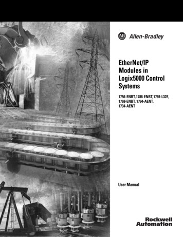
8 1769-L32E, 1769-L35E CompactLogix Controller1. Remove the battery door by sliding it forward.IMPORTANT2.Do not remove the plastic insulation covering the battery. The insulation is necessaryto protect the battery contacts.Insert the battery connector into the connector port.The connector is keyed to be installed with the correctpolarity.3. Insert the battery into the battery port in the battery door.Battery4. Slide the battery door back until it clicks into position.Publication 1769-IN020-C-EN-P - July 2007
1769-L32E, 1769-L35E CompactLogix Controller 9Install a 1784-CF64 or 1784-CF128 Industrial CompactFlash Card(optional)ATTENTIONDo not remove the CompactFlash card while the controller is reading from or writing tothe card, as indicated by a flashing green CF status indicator. This could corrupt the dataon the card or in the controller, as well as corrupt the latest firmware in the controller.The optional industrial CompactFlash card provides nonvolatilememory for a CompactLogix controller. The card is not required forcontroller operation.Follow this procedure to install the card.WARNINGWhen you insert or remove the CompactFlash Card while power is on, an electrical arc canoccur. This could cause an explosion in hazardous location installations.Be sure that power is removed or the area is nonhazardous before proceeding.1. Push the locking tab to the right andinsert the industrial CompactFlashcard into the socket on the front ofthe controller.The label of the CompactFlash cardfaces toward the left. Match theorientation arrow on the card withthe arrow on the front of thecontroller.2. To remove the CompactFlash card,push the locking tab away from theCompactFlash card and pull theCompactFlash card from the socket.Assemble the SystemThe controller can be attached to an adjacent I/O module or powersupply before or after mounting. For mounting instructions, seePublication 1769-IN020-C-EN-P - July 2007
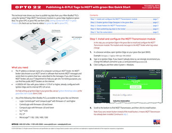
10 1769-L32E, 1769-L35E CompactLogix ControllerGrounding Considerations on page 12 or DIN Rail Mounting on page14.WARNINGThe CompactLogix controller is not designed for removal and insertion under power.If you insert or remove the module while backplane power is on, an electrical arc canoccur. This could cause an explosion in hazardous location installations.Be sure that power is removed or the area is nonhazardous before proceeding.This procedure shows you how to install the controller in aCompactLogix system.CADBFEB1. Disconnect line power.2. Check that the lever of the adjacent module (A) is in theunlocked (fully right) position.3. Use the upper and lower tongue-and-groove slots (B) tosecure the modules together.4. Move the module back along the tongue-and-groove slotsuntil the bus connectors line up with each other.5. Use your fingers or a small screwdriver to push the module’sbus lever back slightly to clear the positioning tab (C).Publication 1769-IN020-C-EN-P - July 2007
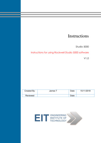
1769-L32E, 1769-L35E CompactLogix Controller 116. Move the module’s bus lever fully to the left (D) until it clicks,being sure it is locked firmly in place.ATTENTIONWhen attaching the controller, power supply, and I/O modules, make sure the busconnectors are securely locked together to be sure of proper electrical connection.7. Attach an end cap terminator (E) to the last module in thesystem by using the tongue-and-groove slots as before.8. Lock the end cap bus terminator (F).Mount the SystemATTENTIONDuring panel or DIN rail mounting of all devices, be sure that all debris (such as metalchips or wire strands) is kept from falling into the controller. Debris that falls into thecontroller could cause damage while the controller is energized.Minimum SpacingMaintain spacing from enclosure walls, wireways, and adjacentequipment. Allow 50 mm (2 in.) of space on all sides, as shown. Thisprovides ventilation and electrical isolation.BottomEnd CapPower SupplyCompact I/OModuleSideCompactLogixController50 mm(1.97 in.)Compact I/OModule50 mm(1.97 in.)Top50 mm(1.97 in.)Side50 mm (1.97 in.)Publication 1769-IN020-C-EN-P - July 2007
12 1769-L32E, 1769-L35E CompactLogix ControllerSystem Dimensions15 mm(.59 in.)67.5 mm(2.68 in.)52.5 mm(2.06 in.)70 mm(2.76 in.)35 mm(1.38 in.)132 mm(5.20 in.)118 mm(4.65 in.)52.5 mm(2.07 in.)TIP35 mm(1.38 in.)35 mm(1.38 in.)35 mm(1.38 in.)35 mm(1.38 in.)Compact I/O expansion cables have the same dimensions as the end caps. Expansioncables can be used on either the right or left end. A 1769-ECR right end cap or 1769-ECLleft end cap terminates the end of the communication bus.Grounding ConsiderationsATTENTIONThis product is grounded through the DIN rail to chassis ground. Use zinc platedyellow-chromate steel DIN rail to assure proper grounding. The use of other DIN railmaterials (such as aluminum or plastic) that can corrode, oxidize, or are poor conductors,can result in improper or intermittent grounding. Secure DIN rail to mounting surfaceapproximately every 200 mm (7.8 in.) and use end-anchors appropriately.This product is intended to be mounted to a well-grounded mountingsurface such as a metal panel. Additional grounding connections fromthe controller’s mounting tabs or DIN rail (if used) are not requiredunless the mounting surface cannot be grounded.Refer to publication 1770-4.1, Industrial Automation Wiring andGrounding Guidelines, for additional information.Publication 1769-IN020-C-EN-P - July 2007
1769-L32E, 1769-L35E CompactLogix Controller 13Panel MountingMount the controller to a panel by using two screws per module. UseM4 or #8 panhead screws. Mounting screws are required on everymodule.This procedure lets you use the assembled modules as a template fordrilling holes in the panel.IMPORTANTDue to module mounting hole tolerance, it is important to follow these procedures.1. On a clean work surface, assemble no more than threemodules.2. Using the assembled modules as a template, carefully mark thecenter of all module-mounting holes on the panel.3. Return the assembled modules to the clean work surface,including any previously mounted modules.4. Drill and tap the mounting holes for the recommended M4 or#8 screw.5. Place the modules back on the panel and check for properhole alignment.TIPThe grounding plate, located where the you install the mounting screws, enables themodule to be grounded when it is panel-mounted.Publication 1769-IN020-C-EN-P - July 2007
14 1769-L32E, 1769-L35E CompactLogix Controller6. Attach the modules to the panel by using the mountingscrews.If you are mounting more modules, mount only the last one of this group and put theothers aside. This reduces remounting time when you are drilling and tapping the nextgroup of modules.TIP7. Repeat steps 1.6 for any remaining modules.DIN Rail MountingThe controller can be mounted on the following DIN rails: EN 50 022 - 35 x 7.5 mm (1.38 x 0.30 in.) EN 50 022 - 35 x 15 mm (1.38 x 0.59 in.)ATTENTIONThis product is grounded through the DIN rail to chassis ground. Use zinc platedyellow-chromate steel DIN rail to assure proper grounding. The use of other DIN railmaterials (for example, aluminum or plastic) that can corrode, oxidize, or are poorconductors, can result in improper or intermittent grounding. Secure DIN rail to mountingsurface approximately every 200 mm (7.8 in.) and use end-anchors appropriately.1. Before mounting the controller on a DIN rail, close the DINrail latches.2. Press the DIN rail mounting area of the controller against theDIN rail.The latches will momentarily open and lock into place.Publication 1769-IN020-C-EN-P - July 2007
1769-L32E, 1769-L35E CompactLogix Controller 15Make RS-232 Connections to the ControllerConnect the 9-pin female end of the serial cable to the serial port ofthe controller.WARNINGIf you connect or disconnect the serial cable with power applied to this module or theserial device on the other end of the cable, an electrical arc can occur. This could causean explosion in hazardous location installations.Be sure that power is removed or the area is nonhazardous before proceeding.RS-232 Cable9-pin, Male D-shell StraightCable End9-pin, Female D-shellRight-angle Cable End1 CD1 CD2 RDX2 RDX3 TXD3 TXD4 DTRCOMMON1747-CP3 or 1756-CP3This cable must be shielded and tied tothe connector housing.4 DTRCOMMON6 DSR6 DSR7 RTS7 RTS8 CTS8 CTS9Straight Cable End9Right-angle Cable EndPublication 1769-IN020-C-EN-P - July 2007
16 1769-L32E, 1769-L35E CompactLogix ControllerDefault Serial ConfigurationChannel 0 and Channel 1 (both serial ports) have the followingdefault communication configuration.ParameterDefaultProtocolDF1 full-duplexCommunication Rate19.2 KbpsParityNoneStation Address0Control LinesNo HandshakingError DetectionBCCEmbedded ResponsesAuto DetectDuplicate Packet (Message) DetectEnabledACK Timeout50 (x 20 ms)NAK Receive Limit3 RetriesENQ Transmit Limit3 RetriesData Bits8Stop Bits1TIPOnly Channel 0 has a default communication push button (see page 17).Publication 1769-IN020-C-EN-P - July 2007
1769-L32E, 1769-L35E CompactLogix Controller 17Using the Channel 0 Default Communication Push ButtonThe Channel 0 default communicationpush button is located on the front of thecontroller in the lower right corner asshown in the illustration.Use the Channel 0 defaultcommunication push button to changefrom the user-defined communicationconfiguration to the defaultcommunication mode. The Channel 0default communication (DCH0) statusindicator turns on (green, steady) to indicate that the defaultcommunication configuration is active.TIPThe default communication push button is recessed.Before pressing the default communication push button, be sure to note the presentcommunication configuration for Channel 0. Pushing the default communication pushbutton resets all configured parameters back to their default settings.To return the channel to its user-configured parameters, you must enter them manuallywhile online with the controller or download them as part of an RSLogix 5000 softwareproject file. To do this online with RSLogix 5000 software, access the ControllerProperties dialog and enter parameters on the Serial Port, System Protocol, and UserProtocol tabs.Publication 1769-IN020-C-EN-P - July 2007
18 1769-L32E, 1769-L35E CompactLogix ControllerMake Ethernet Connections to the ControllerThe 1769-L32E and 1769-L35E controllers ship with the BOOTP utilityenabled. You must assign an IP address to the Ethernet port in orderfor the controller to communicate over an EtherNet/IP network.WARNINGIf you connect or disconnect the communications cable with power applied to this moduleor any device on the network, an electrical arc can occur. This could cause an explosion inhazardous location installations.Be sure that power is removed or the area is nonhazardous before proceeding.Connect the RJ-45 connector of the Ethernet cable to the Ethernetport (top port, CH1) on the controller.ATTENTIONDo not plug a DH-485 network cable or a NAP port cable into the Ethernet port.Undesirable behavior and/or damage to the port may result.8 ------ NC7 ------ NC6 ------ RD5 ------ NC4 ------ NC3 ------ RD 2 ------ TD1 ------ TD Publication 1769-IN020-C-EN-P - July 2007
1769-L32E, 1769-L35E CompactLogix Controller 19Assigning an IP addressYou can set the IP address using any of these utilities: Rockwell BOOTP Utility (available with RSLinx and RSLogix5000 software) RSLinx software RSLogix 5000 softwareUse BOOTP to set the IP addressThe BOOTP utility is a standalone program that is located in one ofthe following directories: RSLinx Tools directory in the Rockwell Software programfolder on the Start menu (the utility is automatically installedwhen you install RSLinx software) Utils directory on the RSLogix 5000 software installation CDFollow this procedure to use the BOOTP utility.1. Start the BOOTP software.2. Select Tools Network Settings.3. Enter the Ethernet mask and gateway.4. Click Ok.Publication 1769-IN020-C-EN-P - July 2007
20 1769-L32E, 1769-L35E CompactLogix ControllerIn the BOOTP Request History dialog you see the hardwareaddresses of devices issuing BOOTP requests.5. Double-click on the hardware address of the device you wantto configure.TIPThe hardware address is on the sticker located on the left-side circuit board of thecontroller next to the battery. See Connect the 1769-BA Battery on page 7 forinstructions on accessing this area.The hardware address will be in this format: 00-0b-db-14-55-35.The New Entry dialog displays the device’s Ethernet Address(MAC).6. Enter the IP address.Publication 1769-IN020-C-EN-P - July 2007
1769-L32E, 1769-L35E CompactLogix Controller 217. Click Ok.8. To permanently assign this configuration to the device,highlight the device and click Disable BOOTP/DHCP.When power is recycled, the device uses the configuration youassigned and does not issue a BootP request.Use RSLinx software to set the IP addressYou can use RSLinx software, version 2.41 or later, to set the IPaddress.1. Make sure the controller that uses the IP address is installedand running.2. Connect to the controller via the serial connection (see page15).3. Start RSLinx software.The RSWho dialog opens.4. Navigate to the Ethernet network.Publication 1769-IN020-C-EN-P - July 2007
22 1769-L32E, 1769-L35E CompactLogix Controller5. Right-click the Ethernet port (not the controller) and selectModule Configuration6. Select the Port Configuration tab.Publication 1769-IN020-C-EN-P - July 2007
1769-L32E, 1769-L35E CompactLogix Controller 237. Click the appropriate radio button to choose the StatusNetwork Configuration type.8. Enter the IP address, network (subnet) mask, and gatewayaddress (if needed).Use RSLogix 5000 software to set the IP addressYou can use RSLogix software to set the IP address.1. Make sure the controller that uses the IP address is installedand running.2. Connect to the controller via the serial connection (see page15).Publication 1769-IN020-C-EN-P - July 2007
24 1769-L32E, 1769-L35E CompactLogix Controller3. Start RSLogix 5000 software. In the Controller Organizer, selectproperties for the Ethernet port.4. Choose the Port Configuration tab.5. Specify the IP address.6. Click Apply.7. Click Ok.This sets the IP address in the hardware. This IP addressshould be the same IP address you assigned under theGeneral tab.Publication 1769-IN020-C-EN-P - July 2007
1769-L32E, 1769-L35E CompactLogix Controller 25Install the Appropriate EDS FilesIf you have RSLinx software, version 2.42 or later, the most currentEDS files were installed with the software. If you are using an earlierversion of RSLinx software, you might need to install EDS files.You need EDS files for these devices: 1769-L32E and 1769-L35E controllers 1769 CompactBus 1769 local adapterAll of these EDS files, except for the 1769 CompactBus file, areupdated for each firmware revision. There is also a version 1 of thecontroller EDS file that you need for new controllers. Each controllerships with revision 1 firmware. In order to update the firmware, youmust have the revision 1 EDS file (0001000E00410100.eds) installedfor the controller.The EDS files are available on the RSLogix 5000 Enterprise Seriessoftware CD. The files are also available athttp://www.ab.com/networks/eds.Load the Controller FirmwareYou must download the current firmware before you can use thecontroller.To load firmware, you can use any of the following: ControlFlash utility that ships with RSLogix 5000 programmingsoftware. AutoFlash that launches through RSLogix 5000 software whenyou try to open or create a project and the controller does nothave the current firmware. A CompactFlash card (catalog number 1784-CF64 or1784-CF128) with valid memory already loaded.If you use the ControlFlash or AutoFlash utilities, you need a serialconnection to the controller.Publication 1769-IN020-C-EN-P - July 2007
26 1769-L32E, 1769-L35E CompactLogix ControllerThe firmware is available with RSLogix 5000 software or you candownload it from the support website. Go tohttp://support.rockwellautomation.com.Follow these steps to download firmware from the support website.1. In the left column (frame), click Technical Support.2. Click Firmware Updates.3. Select the firmware revision.4. Enter the serial number of your RSLogix 5000 programmingsoftware.Publication 1769-IN020-C-EN-P - July 2007
1769-L32E, 1769-L35E CompactLogix Controller 27Use the ControlFlash Utility to Load FirmwareYou can use the ControlFlash utility to load firmware through a serialconnection.1. Make sure the appropriate network connection is made beforestarting.2. Start the ControlFlash utility.3. When the Welcome dialog appears, click Next.4. Choose the catalog number of the controller and click Next.5. Expand the network until you see the controller.6. If the required network is not shown, first configure a driverfor the network in RSLinx software.7. Choose the controller and click Ok.8. Choose the revision level to which you want to update thecontroller and click Next.9. To start the update of the controller, click Finish and then clickYes.10. After the controller is updated, the status dialog displaysUpdate complete.11. Click Ok.12. To close the ControlFlash utility, click Cancel and then clickYes.Publication 1769-IN020-C-EN-P - July 2007
28 1769-L32E, 1769-L35E CompactLogix ControllerUse AutoFlash to Load FirmwareYou can use AutoFlash to load firmware through a serial connection.1. Make sure the appropriate network connection is made beforestarting.2. Use RSLogix 5000 programming software to create a controllerproject.This automatically launches AutoFlash.3. Choose the catalog number of the controller and click Next.4. Expand the network until you see the controller.If the required network is not shown, first configure a driverfor the network in RSLinx software.5. Choose the controller and click Ok.6. Choose the revision level to which you want to update thecontroller and click Next.7. To start the update of the controller, click Finish and then clickYes.After the controller is updated, the status dialog displaysUpdate complete.8. Click Ok.9. To close the AutoFlash utility, click Cancel and then click Yes.Publication 1769-IN020-C-EN-P - July 2007
1769-L32E, 1769-L35E CompactLogix Controller 29Use a CompactFlash Card to Load FirmwareIf you have an existing controller that is already configured and hasfirmware loaded, you can store the current controller user programand firmware on the CompactFlash card and use that card to updateother controllers.1. Use RSLogix 5000 software to store the controller userprogram and firmware of a currently configured controller tothe CompactFlash card.2. Access the Nonvolatile Memory tab of the ControllerProperties dialog.Be sure to select Load Image On Powerup when you save tothe card.3. Remove the card and insert it into a controller that will use thesame firmware and controller user program.When you apply power to the second controller, the imagestored on the CompactFlash card is loaded into the controller.Publication 1769-IN020-C-EN-P - July 2007
30 1769-L32E, 1769-L35E CompactLogix ControllerSelect the Controller’s Operating ModeUse the keyswitch on the front panel of the controller to determinethe controller’s operating mode.KeyswitchPositionRunDescription Uploa
1769-L32E, 1769-L35E CompactLogix Controller 5 Publication 1769-IN020-C-EN-P - July 2007 Environment and Enclosure ATTENTION This equipment is intended for use in a Pollution Degree 2 industrial environment, in overvoltage Category II applications (as defined in IEC publication 60664-1), at altitudes