Transcription
Logix 5000 ControllersFunction Block Diagram1756 ControlLogix, 1756 GuardLogix, 1769 CompactLogix,1769 Compact GuardLogix, 1789 SoftLogix, 5069CompactLogix, 5069 Compact GuardLogix, Studio 5000Logix EmulateRockwell Automation Publication 1756-PM009J-EN-P - March 2022Supercedes Publication 1756-PM009I-EN-P - September 2020Programming ManualOriginal Instructions
Logix 5000 Controllers Function Block DiagramImportant User InformationRead this document and the documents listed in the additional resources section about installation, configuration, andoperation of this equipment before you install, configure, operate, or maintain this product. Users are required to familiarizethemselves with installation and wiring instructions in addition to requirements of all applicable codes, laws, and standards.Activities including installation, adjustments, putting into service, use, assembly, disassembly, and maintenance are required tobe carried out by suitably trained personnel in accordance with applicable code of practice.If this equipment is used in a manner not specified by the manufacturer, the protection provided by the equipment may beimpaired.In no event will Rockwell Automation, Inc. be responsible or liable for indirect or consequential damages resulting from the useor application of this equipment.The examples and diagrams in this manual are included solely for illustrative purposes. Because of the many variables andrequirements associated with any particular installation, Rockwell Automation, Inc. cannot assume responsibility or liability foractual use based on the examples and diagrams.No patent liability is assumed by Rockwell Automation, Inc. with respect to use of information, circuits, equipment, or softwaredescribed in this manual.Reproduction of the contents of this manual, in whole or in part, without written permission of Rockwell Automation, Inc., isprohibited.Throughout this manual, when necessary, we use notes to make you aware of safety considerations.WARNING: Identifies information about practices or circumstances that can cause an explosion in a hazardous environment, which may lead to personal injuryor death, property damage, or economic loss.ATTENTION: Identifies information about practices or circumstances that can lead to personal injury or death, property damage, or economic loss. Attentionshelp you identify a hazard, avoid a hazard, and recognize the consequence.IMPORTANT Identifies information that is critical for successful application and understanding of the product.Labels may also be on or inside the equipment to provide specific precautions.SHOCK HAZARD: Labels may be on or inside the equipment, for example, a drive or motor, to alert people that dangerous voltage may be present.BURN HAZARD: Labels may be on or inside the equipment, for example, a drive or motor, to alert people that surfaces may reach dangerous temperatures.ARC FLASH HAZARD: Labels may be on or inside the equipment, for example, a motor control center, to alert people to potential Arc Flash. Arc Flash will causesevere injury or death. Wear proper Personal Protective Equipment (PPE). Follow ALL Regulatory requirements for safe work practices and for PersonalProtective Equipment (PPE).Rockwell Automation recognizes that some of the terms that are currently used in our industry and in this publication are not inalignment with the movement toward inclusive language in technology. We are proactively collaborating with industry peers tofind alternatives to such terms and making changes to our products and content. Please excuse the use of such terms in ourcontent while we implement these changes.2Rockwell Automation Publication 1756-PM009J-EN-P - March 2022
Summary of changesThis manual includes new and updated information. Use these referencetables to locate changed information.Grammatical and editorial style changes are not included in this summary.Global changesNone in this release.New or enhanced featuresThis table contains a list of topics changed in this version, the reason for thechange, and a link to the topic that contains the changed information.ChangeTopicUpdated Legal notices.Legal notices on page 8Rockwell Automation Publication 1756-PM009J-EN-P - March 20223
Table of ContentsSummary of changesPrefaceProgram a Function BlockDiagramIndexStudio 5000 environment . 7Additional resources . 8Legal notices . 8Chapter 1Introduction . 11Choose the function block elements . 12Choose a tag name for an element . 12Define the order of execution . 13Data latching . 13Order of execution . 15Resolve a loop . 16Resolve data flow between two blocks . 17Create a one scan delay . 17Summary. 18Identify any connectors . 18Define program/operator control . 18Add a sheet . 21Add a function block element . 21Use functions . 22Create a text box .23Language switching . 24Connect elements . 25Show or hide a pin . 25Wire elements together . 25Mark a wire with the Assume Data Available indicator . 25Assign a tag . 26Create and assign a new tag . 26Assign an existing tag . 27Assign an immediate value (constant). 28Use an IREF . 28Enter a value in the tag of a block . 28Connect blocks with an OCON and ICON . 28Add an OCON . 29Add an ICON . 29Rename a wire connector . 29Rename a connector group . 29Verify the routine . 30Rockwell Automation Publication 1756-PM009J-EN-P - March 20225
PrefaceThis manual shows how to program Logix 5000 controllers with the functionblock diagram (FBD) programming language. This manual is one of a set ofrelated manuals that show common procedures for programming andoperating Logix 5000 controllers.For a complete list of common procedures manuals, refer to the Logix 5000Controllers Common Procedures Programming Manual, publication1756-PM001.The term Logix 5000 controller refers to any controller based on the Logix5000 operating system.Rockwell Automation recognizes that some of the terms that are currentlyused in our industry and in this publication are not in alignment with themovement toward inclusive language in technology. We are proactivelycollaborating with industry peers to find alternatives to such terms andmaking changes to our products and content. Please excuse the use of suchterms in our content while we implement these changes.Studio 5000 environmentThe Studio 5000 Automation Engineering & Design Environment combinesengineering and design elements into a common environment. The firstelement is the Studio 5000 Logix Designer application. The Logix Designerapplication is the rebranding of RSLogix 5000 software and will continue tobe the product to program Logix 5000 controllers for discrete, process,batch, motion, safety, and drive-based solutions.The Studio 5000 environment is the foundation for the future ofRockwell Automation engineering design tools and capabilities. The Studio5000 environment is the one place for design engineers to develop allelements of their control system.Rockwell Automation Publication 1756-PM009J-EN-P - March 20227
PrefaceAdditional resourcesThese documents contain additional information concerning relatedRockwell Automation products.ResourceDescriptionIndustrial Automation Wiring and Grounding Guidelines,publication 1770-4.1Provides general guidelines for installing a RockwellAutomation industrial system.Product Certifications webpage, available athttp://ab.rockwellautomation.comProvides declarations of conformity, certificates, andother certification details.View or download publications athttp://www.rockwellautomation.com/literature. To order paper copies oftechnical documentation, contact the local Rockwell Automation distributoror sales representative.Legal noticesRockwell Automation publishes legal notices, such as privacy policies, licenseagreements, trademark disclosures, and other terms and conditions on theLegal Notices page of the Rockwell Automation website.End User License Agreement (EULA)You can view the Rockwell Automation End User License Agreement (EULA)by opening the license.rtf file located in your product's install folder on yourhard drive.The default location of this file is:C:\Program Files (x86)\Common Files\Rockwell\license.rtf.Open Source Software LicensesThe software included in this product contains copyrighted software that islicensed under one or more open source licenses.You can view a full list of all open source software used in this product andtheir corresponding licenses by opening the oss license.txt file located in yourproduct's OPENSOURCE folder on your hard drive. This file is divided intothese sections: ComponentsIncludes the name of the open source component, its version number,and the type of license. Copyright TextIncludes the name of the open source component, its version number,and the copyright declaration. LicensesIncludes the name of the license, the list of open source componentsciting the license, and the terms of the license.The default location of this file is:8Rockwell Automation Publication 1756-PM009J-EN-P - March 2022
PrefaceC:\Program Files (x86)\Common Files\Rockwell\Help\ productname \Release Notes\OPENSOURCE\oss licenses.txt.You may obtain Corresponding Source code for open source packagesincluded in this product from their respective project web site(s).Alternatively, you may obtain complete Corresponding Source code bycontacting Rockwell Automation via the Contact form on the RockwellAutomation bout-us/contact/contact.page.Please include "Open Source" as part of the request text.Rockwell Automation Publication 1756-PM009J-EN-P - March 20229
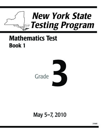
Chapter 1Program a Function Block DiagramIntroductionTo make it easier to navigate through a function block routine, divide theroutine into a series of sheets. Sheets help organize function blocks and make them easier to locate.They do not affect the order in which the function blocks execute. When the routine executes, all the sheets execute. In general, use one sheet for each device, such as a motor or valve.ExampleFunction block routine divided into sheets:Rockwell Automation Publication 1756-PM009J-EN-P - March 202211
Chapter 1Program a Function Block DiagramChoose the function blockelementsUse these elements to control a device:Guidelines to choose the function block elements:To:Use this element:Supply a value from an input device or tagInput reference (IREF)Send a value to an output device or tagOutput reference (OREF)Perform an operation on an input value or values and produce an output valueor valuesFunction block or functionFunctions are similar to function blocks, but do not require backing tags, requireless memory than function blocks, sometimes execute more quickly, and useless space in a function block diagram.Tip: Functions are available only in Logix Designer versions 32 and later onCompactLogix 5380, CompactLogix 5480, ControlLogix 5580, CompactGuardLogix 5380, and GuardLogix 5580 controllers.Output wire connector (OCON) and an input wire connector (ICON)Transfer data between function blocks when they are: Far apart on the same sheet. On different sheets within the same routine.Disperse data to several points in the routineChoose a tag name for anelement12Single output wire connector (OCON) and multiple input wire connectors (ICON)Each function block uses a tag to store configuration and status informationabout the instruction. The Logix Designer application automatically creates a tag for eachnew function block instruction. Use this tag, rename the tag, or assigna different tag. For IREFs and OREFs, create a tag or assign an existing tag.Rockwell Automation Publication 1756-PM009J-EN-P - March 2022
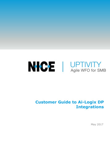
Chapter 1Program a Function Block DiagramFor a:Specify:Tagtag nameBit number of a larger data typeMember of a structureElement of a one dimension arrayElement of a two dimension arrayElement of a three dimension arraytag name.bit numbertag name.member nametag name[x]tag name[x,y]tag name[x,y,z]Element of an array within a structureMember of an element of an arraytag name.member name[x]tag name[x,y,z].member namewhere:x is the location of the element in the first dimension.y is the location of the element in the second dimension.z is the location of the element in the third dimension.For a structure within a structure, add an additional member name.Define the order ofexecutionDefine execution order (flow of data) by wiring elements together andindicating any input (feedback) wires, if necessary. The location of a blockdoes not affect the order in which the blocks execute.Data latchingWhen an IREF specifies input data for a function block instruction, the datain that IREF is latched for the scan of the function block routine. The IREFlatches data from program-scoped and controller-scoped tags. The controllerupdates all IREF data at the beginning of each scan as shown in this diagram.In this example, the value of tagA is stored at the beginning of the executionof the routine. The stored value is used when Block 01 executes. The samestored value is also used when Block 02 executes. If the value of tagA changesRockwell Automation Publication 1756-PM009J-EN-P - March 202213
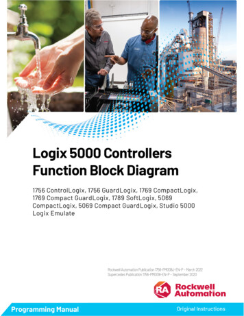
Chapter 1Program a Function Block Diagramduring execution of the routine, the stored value of tagA in the IREF does notchange until the next execution of the routine.This example is the same as the previous example. The value of tagA is storedonly once at the beginning of the execution of the routine. The routine usesthis stored value throughout the routine.With version 11 and later of the application, use the same tag in multipleIREFs and an OREF in the same routine. Because the values of tags in IREFsare latched every scan through the routine, all IREFs use the same value, evenif an OREF obtains a different tag value during execution of the routine. Inthis example, if tagA has a value of 25.4 when the routine starts executing thisscan, and Block 01 changes the value of tagA to 50.9, the second IREF wiredinto Block 02 still uses a value of 25.4 when Block 02 executes this scan.14Rockwell Automation Publication 1756-PM009J-EN-P - March 2022
Chapter 1Program a Function Block DiagramThe new tagA value of 50.9 is not used by any IREFs in this routine until thestart of the next scan.Order of executionThe Logix Designer application automatically determines the order ofexecution for the function blocks in a routine when: Verifying a function block routine. Verifying a project that contains a function block routine. Downloading a project that contains a function block routine.Define the order of execution by wiring function blocks together andindicating the data flow of any feedback wires, if necessary.If function blocks are not wired together, it does not matter which blockexecutes first. There is no data flow between the blocks.If the blocks are wired sequentially, the order of execution moves from inputto output. The inputs of a block require data to be available before thecontroller can execute that block. In this example, block 2 has to executebefore block 3 because the outputs of block 2 feed the inputs of block 3.Rockwell Automation Publication 1756-PM009J-EN-P - March 202215
Chapter 1Program a Function Block DiagramThe order of execution is only relative to the blocks that are wired together.The two groups of blocks in this example are not wired together. The blockswithin a specific group execute in the appropriate order in relation to theblocks in that group.Resolve a loopTo create a feedback loop around a block, wire an output pin of the block to aninput pin of the same block. In this example, the loop contains only a singleblock, so execution order does not matter.If a group of blocks are in a loop, the controller cannot determine which blockto execute first, and it cannot resolve the loop, as illustrated in this example.To identify which block to execute first, mark the input wire that creates theloop (the feedback wire) with the Assume Data Available indicator. In thisexample, block 1 uses the output from block 3 that was produced in theprevious execution of the routine.The Assume Data Available indicator defines the data flow within the loop.The arrow indicates that the data serves as input to the first block in the loop.Do not mark all the wires of a loop with the Assume Data Available indicator.16Rockwell Automation Publication 1756-PM009J-EN-P - March 2022
Chapter 1This example is OK.The Assume Data Available indicator defines the data flow within the loop.Resolve data flow betweentwo blocksProgram a Function Block DiagramThis example is not OK.The controller cannot resolve the loop because all the wires use the Assume DataAvailable indicator.When using two or more wires to connect two blocks, use the same data flowindicators for all of the wires between the two blocks.This is OKThis is NOT OKIn this example, neither wire uses the Assume Data Available indicator.In this example, only one wire uses the Assume Data Available indicator.In this example, both wires use the Assume Data Available indicator.Create a one scan delayUse the Assume Data Available indicator to produce a one scan delay betweenblocks. In this example, block 1 executes first. It uses the output from block 2that was produced in the previous scan of the routine.Rockwell Automation Publication 1756-PM009J-EN-P - March 202217
Chapter 1Program a Function Block DiagramSummaryA function block routine executes in this order.1. The controller latches all data values in IREFs.2. The controller executes the other function blocks in the orderdetermined by how they are wired.3. The controller writes outputs in OREFs.Identify any connectorsLike wires, connectors transfer data from output pins to input pins. Useconnectors when: The elements to connect are on different sheets within the sameroutine. A wire is difficult to route around other wires or elements. Data should be dispersed to several points in the routine.To use connectors, use these rules.Define program/operatorcontrol Each OCON requires a unique name. Each OCON must have at least one corresponding ICON, such as anICON with the same name as the OCON. Multiple ICONs can reference the same OCON. This allows dispersal ofdata to several points in a routine.These instructions support the concept of Program/Operator control. Enhanced Select (ESEL)Totalizer (TOT)Enhanced PID (PIDE)Ramp/Soak (RMPS)Discrete 2-State Device (D2SD)Discrete 3-State Device (D3SD)Program/Operator control allows simultaneous control of these instructionsfrom the user program and from an operator interface device. When inProgram control, the instruction is controlled by the Program inputs to theinstruction. When in Operator control, the instruction is controlled by theOperator inputs to the instruction.Program or Operator control is determined by using these inputs:18Rockwell Automation Publication 1756-PM009J-EN-P - March 2022
Chapter 1Program a Function Block DiagramInputDescription.ProgProgReqA program request to go to Program control.ProgOperReq.OperProgReqA program request to go to Operator control.An operator request to go to Program control.OperOperReqAn operator request to go to Operator control.To determine whether an instruction is in Program or Operator control,examine the ProgOper output. If ProgOper bit is set, the instruction is inProgram control. If ProgOper bit is cleared, the instruction is inOperator control.Operator control takes precedence over Program control if both input requestbits are set. For example, if ProgProgReq and ProgOperReq bits are set, theinstruction goes to Operator control.The Program request inputs take precedence over the Operator requestinputs. This provides the capability to use the ProgProgReq and ProgOperReqinputs to lock an instruction in a desired control.For example, assume that a Totalizer instruction is always used in Operatorcontrol, and the user program never controls the running or stopping of theTotalizer. In this case, wire a literal value of 1 into the ProgOperReq input.This prevents the operator from ever putting the Totalizer into Programcontrol by setting the OperProgReq input from an operator interface device.Rockwell Automation Publication 1756-PM009J-EN-P - March 202219
Chapter 1Program a Function Block DiagramLikewise, constantly setting the ProgProgReq input can "lock" the instructioninto Program control. This is useful for automatic startup sequences when theprogram should control the action of the instruction without an operatorinadvertently taking control of the instruction. In this example, the programsets the ProgProgReq input during the startup, and clears the ProgProgReqinput once the startup is complete. Once the ProgProgReq input is cleared,the instruction remains in Program control until it receives a request tochange. For example, the operator sets the OperOperReq input from afaceplate to take control of that instruction. This example shows how to lockan instruction into Program control.Operator request inputs to an instruction are always cleared by theinstruction when it executes. This lets operator interface work with theseinstructions by setting the desired mode request bit. It is not necessary toprogram the operator interface to reset the request bits. For example, if anoperator interface sets the OperAutoReq input to a PIDE instruction, whenthe PIDE instruction executes, it determines the appropriate response andclears the OperAutoReq.Program request inputs are not normally cleared by the instruction becausethese are normally wired as inputs into the instruction. If the instructionclears these inputs, the input would get set again by the wired input. In somesituations, other logic should set the Program requests to be cleared by theinstruction. In this case, set the ProgValueReset input and the instructionalways clears the Program mode request inputs when it executes.20Rockwell Automation Publication 1756-PM009J-EN-P - March 2022
Chapter 1Program a Function Block DiagramIn this example, a rung of ladder logic in another routine is used to one-shotlatch a ProgAutoReq input to a PIDE instruction when a push button ispushed. Because the PIDE instruction automatically clears the Program moderequests, no ladder logic is required to clear the ProgAutoReq input after theroutine executes. The PIDE instruction receives only one request to go to Autoevery time the push button is pressed.ExampleWhen the TIC101AutoReq button is pressed, one-shot latch ProgAutoReq forthe PIDE instruction TIC101.TIC101 is configured with the ProgValueReset input set, so when the PIDEinstruction executes, it automatically clears ProgAutoReq.Add a sheetTo add a sheet to a function block routine:1. On the Sheet toolbar, click Add SheetAdd a function blockelement.2. In the Description box, type a description of the sheet. Follow theIEC-1131 naming standard. The description must not be greater than50 characters.Use the Language Element toolbar to add a function block element to aroutine.To add a function block element1. On the Language Element toolbar, click the element to add.Rockwell Automation Publication 1756-PM009J-EN-P - March 202221
Chapter 1Program a Function Block Diagram2. On the function block diagram, drag the element to the desiredlocation.Tip: Alternatively, drag the button for the element directly to the desired location.IMPORTANT Use caution when copying and pasting components between different versions ofthe Logix Designer application. The application only supports pasting to the sameversion or newer version. Pasting to a prior version of the application is notsupported. When pasting to a prior version, the paste action may succeed but theresults may not be as intended.Use functionsUse Function Block functions to carry out mathematical, comparison, andlogical operations. Functions in the Function Block Diagram Editor aresimilar to instructions, but do not require backing tags, require less memorythan instructions, sometimes execute more quickly, and use less space in afunction block diagram.Tip:Function Block functions are available only on CompactLogix 5380,CompactLogix 5480, ControlLogix 5580, Compact GuardLogix 5380, andGuardLogix 5580 controllers.This table lists the functions that are available in the categories on the FBDElement toolbar:Toolbar categoryFunctionAdvanced MathLN (Natural Log)LOG (Log Base 10)XPY (X to the power of Y)Compute / MathADDSUBMULDIV22Rockwell Automation Publication 1756-PM009J-EN-P - March 2022Symbol
Chapter 1Toolbar categoryFunctionProgram a Function Block DiagramSymbolMOD (Modulo)SQR (Square Root)NEG (Negate)ABS (Absolute Value)CompareEQU (Equal To)GEQ (Greater Than or Equal To)GRT (Greater Than)LEQ (Less Than or Equal To)LES (Less Than)LIM (Limit)MEQ (Mask Equal To)NEQ (Not Equal To)Math ConversionsDEG (Radians to Degrees)RAD (Degrees to Radians)TRN (Truncate)Move / Boolean LogicalAND (Bitwise And)BAND (Boolean AND)BXOR (Boolean Exclusive OR)BNOT (Boolean NOT)BOR (Boolean OR)NOT (Bitwise Not)OR (Bitwise Inclusive Or)XOR (Bitwise Exclusive Or)TrigonometryACS (Arc Cosine)ASN (Arc Sine)ATN (Arc Tangent)COS (Cosine)SIN (Sine)TAN (Tangent)Create a text boxCreate a text box to add notes that clarify the function of an FBD element,such as blocks, references, and connectors. Text boxes are only stored in theoffline, ACD project file. Text boxes are not downloaded into controllermemory.1. On the Language Element toolbar, click Text Box.2. In the the FBD editor, drag the text box to a location near the elementto which it applies.3. Double-click the text box and enter the desired text.4. Press Ctrl Enter.Rockwell Automation Publication 1756-PM009J-EN-P - March 202223
Chapter 1Program a Function Block Diagram5. To attach the text box to a specific element, click the pin symbol in thetext box and click the corresponding element. A green dot shows avalid connection point.Language switchingVersions 17 and later of the Logix Designer application can display projectdocumentation, such as tag descriptions and rung comments, for anysupported localized language. Store project documentation for multiplelanguages in a single project file rather than in language-specific project files.Define all the localized languages that the project will support and set thecurrent, default, and optional custom localized language. The defaultlanguage is used if the current content of the language is blank for a particularcomponent of the project. Use a custom language to tailor documentation to aspecific type of project file user.Enter the localized descriptions in a project by programming in that language,or by using the import/export utility to translate the documentation offlineand import it back into the project. When language switching is enabled,users can dynamically switch between languages.Project documentation that supports multiple translations within a projectincludes: Component descriptions in tags, routines, programs, user-defineddata types, and Add-On Instructions. Equipment phases. Trends. Controllers. Alarm Messages (in ALARM ANALOG and ALARM DIGITALconfiguration). Tasks. Property descriptions for modules in the Controller Organizer. Rung comments, SFC text boxes, and FBD text boxes.For more information on enabling a project to support multiple translationsof project documentat
Programming Manual Original Instructions Logix 5000 Controllers Function Block Diagram 1756 ControlLogix, 1756 GuardLogix, 1769 CompactLogix, 1769 Compact GuardLogix, 1789 SoftLogix, 5069 . C:\Program Files (x86)\Common Files\Rockwell\license.rtf. Open Source Software Licenses