Transcription
User Manual1769 CompactLogix Controllers User ManualCatalog Numbers 1769-L31, 1769-L32C, 1769-L32E, 1769-L35CR, 1769-L35E
Important User InformationSolid-state equipment has operational characteristics differing from those of electromechanical equipment. SafetyGuidelines for the Application, Installation and Maintenance of Solid State Controls (publication SGI-1.1 available fromyour local Rockwell Automation sales office or online at http://www.rockwellautomation.com/literature/) describes someimportant differences between solid-state equipment and hard-wired electromechanical devices. Because of this difference,and also because of the wide variety of uses for solid-state equipment, all persons responsible for applying this equipmentmust satisfy themselves that each intended application of this equipment is acceptable.In no event will Rockwell Automation, Inc. be responsible or liable for indirect or consequential damages resulting from theuse or application of this equipment.The examples and diagrams in this manual are included solely for illustrative purposes. Because of the many variables andrequirements associated with any particular installation, Rockwell Automation, Inc. cannot assume responsibility orliability for actual use based on the examples and diagrams.No patent liability is assumed by Rockwell Automation, Inc. with respect to use of information, circuits, equipment, orsoftware described in this manual.Reproduction of the contents of this manual, in whole or in part, without written permission of Rockwell Automation,Inc., is prohibited.Throughout this manual, when necessary, we use notes to make you aware of safety considerations.WARNING: Identifies information about practices or circumstances that can cause an explosion in a hazardous environment,which may lead to personal injury or death, property damage, or economic loss.ATTENTION: Identifies information about practices or circumstances that can lead to personal injury or death, propertydamage, or economic loss. Attentions help you identify a hazard, avoid a hazard, and recognize the consequence.SHOCK HAZARD: Labels may be on or inside the equipment, for example, a drive or motor, to alert people that dangerousvoltage may be present.BURN HAZARD: Labels may be on or inside the equipment, for example, a drive or motor, to alert people that surfaces mayreach dangerous temperatures.IMPORTANTIdentifies information that is critical for successful application and understanding of the product.Allen-Bradley, Rockwell Automation, Rockwell Software, CompactLogix, ControlFLASH, Logix5000, RSLinx, RSLogix, PanelView, PhaseManager, ControlLogix, PanelView, Ultra, PowerFlex, FlexLogix, PLC-5,DriveLogix, SLC, MicroLogix, and TechConnect are trademarks of Rockwell Automation, Inc.Trademarks not belonging to Rockwell Automation are property of their respective companies.
Summary of ChangesThis manual contains new and updated information. Changes throughout thisrevision are marked by change bars, as shown to the right of this paragraph.New and UpdatedInformationThis table contains the changes made to this revision.TopicPageUpdated the Verify Compatibility section18Rockwell Automation Publication 1769-UM011I-EN-P - February 20133
Summary of ChangesNotes:4Rockwell Automation Publication 1769-UM011I-EN-P - February 2013
Table of ContentsPrefaceAdditional Resources . . . . . . . . . . . . . . . . . . . . . . . . . . . . . . . . . . . . . . . . . . . . . . . 9Chapter 11769 CompactLogix ControllersOverviewAbout the 1769 CompactLogix Controller . . . . . . . . . . . . . . . . . . . . . . . . . 11Design a CompactLogix System . . . . . . . . . . . . . . . . . . . . . . . . . . . . . . . . . . . 13Chapter 2Install the 1769-L3x ControllersVerify Compatibility . . . . . . . . . . . . . . . . . . . . . . . . . . . . . . . . . . . . . . . . . . . . .Before You Begin . . . . . . . . . . . . . . . . . . . . . . . . . . . . . . . . . . . . . . . . . . . . . . . .Parts List . . . . . . . . . . . . . . . . . . . . . . . . . . . . . . . . . . . . . . . . . . . . . . . . . . . .Set the Node Address (ControlNet only) . . . . . . . . . . . . . . . . . . . . . . . . . .Connect the 1769-BA Battery. . . . . . . . . . . . . . . . . . . . . . . . . . . . . . . . . . . . .Install a CompactFlash Card (optional) . . . . . . . . . . . . . . . . . . . . . . . . . . . .Assemble the System . . . . . . . . . . . . . . . . . . . . . . . . . . . . . . . . . . . . . . . . . . . . .Mount the System. . . . . . . . . . . . . . . . . . . . . . . . . . . . . . . . . . . . . . . . . . . . . . . .Minimum Spacing. . . . . . . . . . . . . . . . . . . . . . . . . . . . . . . . . . . . . . . . . . . .Dimensions . . . . . . . . . . . . . . . . . . . . . . . . . . . . . . . . . . . . . . . . . . . . . . . . . .Ground the Wiring. . . . . . . . . . . . . . . . . . . . . . . . . . . . . . . . . . . . . . . . . . .Mount the Panel . . . . . . . . . . . . . . . . . . . . . . . . . . . . . . . . . . . . . . . . . . . . .Mount the Controller on the DIN Rail . . . . . . . . . . . . . . . . . . . . . . . .Make RS-232 Connections to the Controller. . . . . . . . . . . . . . . . . . . . . . .RS-232 Cable . . . . . . . . . . . . . . . . . . . . . . . . . . . . . . . . . . . . . . . . . . . . . . . .Optical Isolator (1769-L31 only) . . . . . . . . . . . . . . . . . . . . . . . . . . . . . .Default Serial Configuration . . . . . . . . . . . . . . . . . . . . . . . . . . . . . . . . . .Using the Channel 0 Default Communication Push Button . . . . .Make Ethernet Connections to the Controller . . . . . . . . . . . . . . . . . . . . .Assign an IP Address. . . . . . . . . . . . . . . . . . . . . . . . . . . . . . . . . . . . . . . . . .Make ControlNet Connections to the Controller . . . . . . . . . . . . . . . . . .Connect the Controller to the Network via a ControlNet Tap . . .Connect a Programming Terminal to the Network viaa 1786-CP Cable . . . . . . . . . . . . . . . . . . . . . . . . . . . . . . . . . . . . . . . . . . . . .Install the Appropriate EDS Files. . . . . . . . . . . . . . . . . . . . . . . . . . . . . . . . . .Load the Controller Firmware . . . . . . . . . . . . . . . . . . . . . . . . . . . . . . . . . . . .Use the ControlFLASH Utility to Load Firmware . . . . . . . . . . . . . .Use AutoFlash to Load Firmware . . . . . . . . . . . . . . . . . . . . . . . . . . . . . .Use a CompactFlash Card to Load Firmware . . . . . . . . . . . . . . . . . . .Select the Controller’s Operating Mode. . . . . . . . . . . . . . . . . . . . . . . . . . . 637373839Chapter 3Connect to the Controller via theSerial PortConnect to the Controller via the Serial Port . . . . . . . . . . . . . . . . . . . . . . .Configure the Serial Driver . . . . . . . . . . . . . . . . . . . . . . . . . . . . . . . . . . . . . . .Select the Controller Path . . . . . . . . . . . . . . . . . . . . . . . . . . . . . . . . . . . . . . . .Controller Options. . . . . . . . . . . . . . . . . . . . . . . . . . . . . . . . . . . . . . . . . . .Rockwell Automation Publication 1769-UM011I-EN-P - February 2013414345465
Table of ContentsChapter 4Communicate over NetworksEtherNet/IP Network Communication . . . . . . . . . . . . . . . . . . . . . . . . . . . .Connections over an EtherNet/IP Network . . . . . . . . . . . . . . . . . . . .ControlNet Network Communication. . . . . . . . . . . . . . . . . . . . . . . . . . . . .Connections over ControlNet Network . . . . . . . . . . . . . . . . . . . . . . . .DeviceNet Communication . . . . . . . . . . . . . . . . . . . . . . . . . . . . . . . . . . . . . . .Serial Communication . . . . . . . . . . . . . . . . . . . . . . . . . . . . . . . . . . . . . . . . . . . .Configure an Isolator . . . . . . . . . . . . . . . . . . . . . . . . . . . . . . . . . . . . . . . . .Communicate with DF1 Devices . . . . . . . . . . . . . . . . . . . . . . . . . . . . . .DF1 Radio Modem Support . . . . . . . . . . . . . . . . . . . . . . . . . . . . . . . . . . .Modbus Support . . . . . . . . . . . . . . . . . . . . . . . . . . . . . . . . . . . . . . . . . . . . .Broadcast Messages over a Serial Port . . . . . . . . . . . . . . . . . . . . . . . . . . .DH-485 Network Communication. . . . . . . . . . . . . . . . . . . . . . . . . . . . . . . .484950525355575961676772Chapter 5Manage Controller CommunicationProduce and Consume Data. . . . . . . . . . . . . . . . . . . . . . . . . . . . . . . . . . . . . . .Send and Receive Messages . . . . . . . . . . . . . . . . . . . . . . . . . . . . . . . . . . . . . . . .Determine Whether to Cache Message Connections . . . . . . . . . . . .Connections . . . . . . . . . . . . . . . . . . . . . . . . . . . . . . . . . . . . . . . . . . . . . . . . . . . . .Calculate Total Connections . . . . . . . . . . . . . . . . . . . . . . . . . . . . . . . . . . . . . .Connections Example . . . . . . . . . . . . . . . . . . . . . . . . . . . . . . . . . . . . . . . . . . . .757677777879Chapter 6Place, Configure, and Monitor I/O6Select I/O Modules. . . . . . . . . . . . . . . . . . . . . . . . . . . . . . . . . . . . . . . . . . . . . . .Validate I/O Layout . . . . . . . . . . . . . . . . . . . . . . . . . . . . . . . . . . . . . . . . . . . . . .Estimate Requested Packet Interval . . . . . . . . . . . . . . . . . . . . . . . . . . . .Calculate System Power Consumption . . . . . . . . . . . . . . . . . . . . . . . . .Validate Placement of I/O Modules . . . . . . . . . . . . . . . . . . . . . . . . . . . .Place Local I/O Modules. . . . . . . . . . . . . . . . . . . . . . . . . . . . . . . . . . . . . . . . . .Configure I/O . . . . . . . . . . . . . . . . . . . . . . . . . . . . . . . . . . . . . . . . . . . . . . . . . . .I/O Connections . . . . . . . . . . . . . . . . . . . . . . . . . . . . . . . . . . . . . . . . . . . . .Configure Distributed I/O on an EtherNet/IP Network . . . . . . . . . . . .Configure Distributed I/O on a ControlNet Network . . . . . . . . . . . . . .Configure Distributed I/O on a DeviceNet Network. . . . . . . . . . . . . . . .Address I/O Data . . . . . . . . . . . . . . . . . . . . . . . . . . . . . . . . . . . . . . . . . . . . . . . .Determine When Data Is Updated . . . . . . . . . . . . . . . . . . . . . . . . . . . . . . . .Monitor I/O Modules . . . . . . . . . . . . . . . . . . . . . . . . . . . . . . . . . . . . . . . . . . . .Display Fault Data . . . . . . . . . . . . . . . . . . . . . . . . . . . . . . . . . . . . . . . . . . . .End-cap Detection and Module Faults. . . . . . . . . . . . . . . . . . . . . . . . . .Reconfigure an I/O Module . . . . . . . . . . . . . . . . . . . . . . . . . . . . . . . . . . . . . . .Reconfigure a Module via RSLogix 5000 Programming Software .Reconfigure a Module via a MSG Instruction . . . . . . . . . . . . . . . . . . .Rockwell Automation Publication 1769-UM011I-EN-P - February 201381828283838687888889909192939394949495
Table of ContentsChapter 7Develop ApplicationsManage Tasks. . . . . . . . . . . . . . . . . . . . . . . . . . . . . . . . . . . . . . . . . . . . . . . . . . . . 97Develop Programs. . . . . . . . . . . . . . . . . . . . . . . . . . . . . . . . . . . . . . . . . . . . . . . . 98Define Tasks . . . . . . . . . . . . . . . . . . . . . . . . . . . . . . . . . . . . . . . . . . . . . . . . . 99Define Programs . . . . . . . . . . . . . . . . . . . . . . . . . . . . . . . . . . . . . . . . . . . . 101Define Routines . . . . . . . . . . . . . . . . . . . . . . . . . . . . . . . . . . . . . . . . . . . . . 101Sample Controller Projects . . . . . . . . . . . . . . . . . . . . . . . . . . . . . . . . . . . 102Organize Tags . . . . . . . . . . . . . . . . . . . . . . . . . . . . . . . . . . . . . . . . . . . . . . . . . . 103Select a Programming Language . . . . . . . . . . . . . . . . . . . . . . . . . . . . . . . . . . 104Add-on Instructions . . . . . . . . . . . . . . . . . . . . . . . . . . . . . . . . . . . . . . . . . 105Monitor Connections . . . . . . . . . . . . . . . . . . . . . . . . . . . . . . . . . . . . . . . . . . . 107Determine if Device Communication Has Timed Out . . . . . . . . . 107Determine if I/O Module Communication Has Timed Out . . . . 108Interrupt the Execution of Logic and Execute the Fault Handler 109Select a System Overhead Time Slice Percentage . . . . . . . . . . . . . . . . . . . 109Chapter 8Configure PhaseManager Application PhaseManager Overview. . . . . . . . . . . . . . . . . . . . . . . . . . . . . . . . . . . . . . . . . 113State Model Overview . . . . . . . . . . . . . . . . . . . . . . . . . . . . . . . . . . . . . . . . . .How Equipment Changes States. . . . . . . . . . . . . . . . . . . . . . . . . . . . . .Manually Change States . . . . . . . . . . . . . . . . . . . . . . . . . . . . . . . . . . . . .Compare PhaseManager to Other State Models . . . . . . . . . . . . . . . . . . .Minimum System Requirements . . . . . . . . . . . . . . . . . . . . . . . . . . . . . . . . .Equipment Phase Instructions . . . . . . . . . . . . . . . . . . . . . . . . . . . . . . . . . . .114116117117118118Chapter 9Use a CompactFlash CardLocate the Controller Serial Number in RSLinx Software . . . . . . .Locate the Controller Serial Number. . . . . . . . . . . . . . . . . . . . . . . . . .Use a CompactFlash Card to Load/Store a User Application . . . . . . .Manually Change Which Project Loads . . . . . . . . . . . . . . . . . . . . . . .Manually Change the Load Parameters. . . . . . . . . . . . . . . . . . . . . . . .Use a CompactFlash Card for Data Storage . . . . . . . . . . . . . . . . . . . . . . .Read and Write User Data to the CompactFlash Card . . . . . . . . . . . . .119121122122124125125Chapter 10Maintain the BatteryBattery Handling . . . . . . . . . . . . . . . . . . . . . . . . . . . . . . . . . . . . . . . . . . . . . . .Check If the Battery Is Low . . . . . . . . . . . . . . . . . . . . . . . . . . . . . . . . . . . . . .Estimate 1769-BA Battery Life . . . . . . . . . . . . . . . . . . . . . . . . . . . . . . . . . . .Store Lithium Batteries . . . . . . . . . . . . . . . . . . . . . . . . . . . . . . . . . . . . . . . . . .Battery Removal . . . . . . . . . . . . . . . . . . . . . . . . . . . . . . . . . . . . . . . . . . . . . . . .Additional Resources . . . . . . . . . . . . . . . . . . . . . . . . . . . . . . . . . . . . . . . . . . . .Rockwell Automation Publication 1769-UM011I-EN-P - February 20131271281281291291307
Table of ContentsAppendix AStatus Indicators1769-L3xx Controllers Status Indicators . . . . . . . . . . . . . . . . . . . . . . . . . .CompactFlash Indicator . . . . . . . . . . . . . . . . . . . . . . . . . . . . . . . . . . . . . . . . .RS-232 Serial Port Status Indicators . . . . . . . . . . . . . . . . . . . . . . . . . . . . . .ControlNet Indicators . . . . . . . . . . . . . . . . . . . . . . . . . . . . . . . . . . . . . . . . . . .Module Status (MS) Indicator . . . . . . . . . . . . . . . . . . . . . . . . . . . . . . . .Network Channel Indicators . . . . . . . . . . . . . . . . . . . . . . . . . . . . . . . . .EtherNet/IP Indicators . . . . . . . . . . . . . . . . . . . . . . . . . . . . . . . . . . . . . . . . . .Module Status (MS) Indicator . . . . . . . . . . . . . . . . . . . . . . . . . . . . . . . .Network Status (NS) Indicator . . . . . . . . . . . . . . . . . . . . . . . . . . . . . . .Link Status (LNK) Indicator . . . . . . . . . . . . . . . . . . . . . . . . . . . . . . . . .131133133133134135135135136136Appendix BDynamic Memory Allocation inCompactLogix ControllersMessages. . . . . . . . . . . . . . . . . . . . . . . . . . . . . . . . . . . . . . . . . . . . . . . . . . . . . . . .RSLinx Tag Optimization. . . . . . . . . . . . . . . . . . . . . . . . . . . . . . . . . . . . . . . .Trends . . . . . . . . . . . . . . . . . . . . . . . . . . . . . . . . . . . . . . . . . . . . . . . . . . . . . . . . .DDE/OPC Topics . . . . . . . . . . . . . . . . . . . . . . . . . . . . . . . . . . . . . . . . . . . . . .Specify Connections per PLC Controller . . . . . . . . . . . . . . . . . . . . . .Number of Connections Needed to Optimize Throughput . . . . .View the Number of Open Connections. . . . . . . . . . . . . . . . . . . . . . .Index8Rockwell Automation Publication 1769-UM011I-EN-P - February 2013138138139139139141141
PrefaceUse this manual to become familiar with the CompactLogix controller and itsfeatures.This manual describes the necessary tasks to install, configure, program, andoperate a CompactLogix system. In some cases, this manual includes references toadditional documentation that provides the more comprehensive details.Additional ResourcesThese documents contain additional information concerning related productsfrom Rockwell Automation.ResourceDescription1769 CompactLogix Controllers Specifications Technical Data, publication 1769-TD005Contains technical specifications and certifications for all CompactLogix controllers.1769-L3x CompactLogix System Quick Start, publication IASIMP-QS001Provides examples of using a 1769-L3x CompactLogix controller to connect to multipledevices over various networks.Logix5000 Controller Design Considerations Reference Manual, publication 1756-RM094Provides guidelines you can follow to optimize your system. This manual also providessystem information you need to make system design choices.Logix5000 Controllers Common Procedures Manual, publication 1756-PM001Guides the development of projects for Logix5000 controllers. It provides links toindividual guides.Logix5000 Controllers General Instruction Set Reference Manual, publication1756-RM003Provides a programmer with details about each available instruction for a Logix5000controller. You should already be familiar with how the Logix5000 controller stores andprocesses data.Logix5000 Controllers Process Control/Drives Instruction Set Reference Manual,publication 1756-RM006Provides a programmer with details about each function block instruction available for aLogix5000 controller. You should already be familiar with how the Logix5000 controllerstores and processes data.EtherNet/IP Modules in Logix5000 Control Systems User Manual, publicationENET-UM001Describes how to install and configure EtherNet/IP modules in Logix5000 control systems.ControlNet Communication Modules in Logix5000 Control Systems User Manual,publication CNET-UM001Describes how to install and configure ControlNet modules in a Logix5000 control system.Industrial Automation Wiring and Grounding Guidelines, publication 1770-4.1Provides general guidelines for installing a Rockwell Automation industrial system.Product Certifications website, http://www.ab.comProvides declarations of conformity, certificates, and other certification details.You can view or download publications athttp:/www.rockwellautomation.com/literature/. To order paper copies oftechnical documentation, contact your local Allen-Bradley distributor orRockwell Automation sales representative.Rockwell Automation Publication 1769-UM011I-EN-P - February 20139
PrefaceNotes:10Rockwell Automation Publication 1769-UM011I-EN-P - February 2013
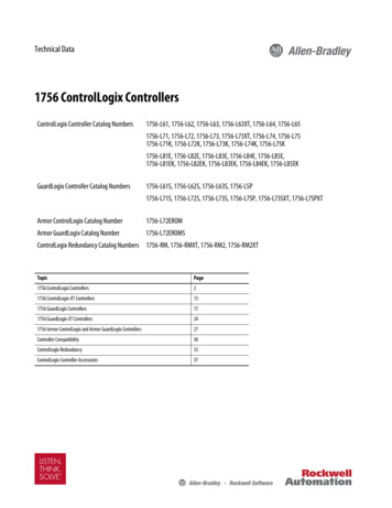
Chapter11769 CompactLogix Controllers OverviewThis chapter introduces the 1769 CompactLogix controllers. These controllersoffer state-of-the-art control, communication, and I/O elements in a distributedcontrol package.About the 1769CompactLogix ControllerThe 1769 CompactLogix controller offers state-of-the-art control,communication, and I/O elements in a distributed control package.Figure 1 - CompactLogix Controller and 1769 I/O ModulesCompactLogix ControllerRockwell Automation Publication 1769-UM011I-EN-P - February 20131769 I/O Modules Connectedto the CompactLogixController11
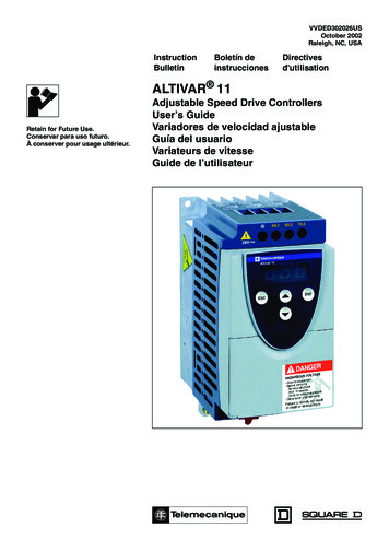
Chapter 11769 CompactLogix Controllers OverviewFor a more flexible system, use: multiple controllers in a single chassis. multiple controllers joined across networks. I/O in multiple platforms that is distributed in many locations andconnected over multiple I/O links.Figure 2 - CompactLogix System Overview1769 I/O ModulesConnected to theCompactLogix ControllerBuilt-in ControlNet orEtherNet/IPCommunication Ports or1769-SDN ModuleConnected to the ControllerEtherNet/IP LinkControlNet LinkDeviceNet Link}Remote I/O ModulesDrivesSensorsEtherNet/IP LinkControlNet LinkDH-485 LinkRS-232ModbusComputersOther ControllersHMI devicesThe CompactLogix controller, part of the Logix family of controllers, provides asmall, powerful, cost-effective system consisting of the following: RSLogix 5000 programming software Built-in communication ports for EtherNet/IP (1769-L32E and 1769L35E only) and ControlNet (1769-L32C and 1769-L35CRonly) networks A 1769-SDN communication interface module providing I/O control andremote device configuration over DeviceNet A built-in serial port on every CompactLogix controller Compact I/O modules providing a compact, DIN-rail or panel-mountedI/O system12Rockwell Automation Publication 1769-UM011I-EN-P - February 2013
1769 CompactLogix Controllers OverviewChapter 1Table 1 - CompactLogix Controller CombinationsControllerAvailable MemoryCommunication OptionsNumber ofTasks SupportedNumber of Local I/OModules Supported1769-L35CR1.5 MB1 port ControlNet - supports redundant media1 port RS-232 serial (system or user protocols)8306161769-L35E1769-L32C1 port EtherNet/IP1 port RS-232 serial (system or user protocols)750 KB1769-L32E1769-L311 port ControlNet1 port RS-232 serial (system or user protocols)1 port EtherNet/IP1 port RS-232 serial (system or user protocols)512 KBDesign a CompactLogixSystem1 port RS-232 serial (system or user protocols)1 port RS-232 serial (system protocol only)4When designing a CompactLogix system, determine the network configurationand the placement of components in each location. To design yourCompactLogix system, you must select the following: I/O devices A communication network Controllers Power supplies SoftwareRockwell Automation Publication 1769-UM011I-EN-P - February 201313
Chapter 11769 CompactLogix Controllers OverviewNotes:14Rockwell Automation Publication 1769-UM011I-EN-P - February 2013
Chapter2Install the 1769-L3x ControllersTopicPageVerify Compatibility18Before You Begin19Set the Node Address (ControlNet only)19Connect the 1769-BA Battery20Install a CompactFlash Card (optional)21Assemble the System22Mount the System23Make RS-232 Connections to the Controller26Make Ethernet Connections to the Controller28Make ControlNet Connections to the Controller32Install the Appropriate EDS Files36Load the Controller Firmware36Select the Controller’s Operating Mode39Use this chapter to install the CompactLogix controller, which must be theleftmost module in the first bank of the system.Rockwell Automation Publication 1769-UM011I-EN-P - February 201315
Chapter 2Install the 1769-L3x ControllersWARNING: This equipment is intended for use in a Pollution Degree 2 industrial environment, in overvoltageCategory II applications (as defined in IEC publication 60664-1), at altitudes up to 2000 meters (6562 ft) withoutderating.This equipment is considered Group 1, Class A industrial equipment according to IEC/CISPR Publication 11. Withoutappropriate precautions, there may be potential difficulties ensuring electromagnetic compatibility in otherenvironments due to conducted as well as radiated disturbance.This equipment is supplied as open-type equipment. It must be mounted within an enclosure that is suitably designedfor those specific environmental conditions that will be present and appropriately designed to prevent personal injuryresulting from accessibility to live parts. The enclosure must have suitable flame-retardant properties to prevent orminimize the spread of flame, complying with a flame spread rating of 5VA, V2, V1, V0 (or equivalent) if non-metallic.The interior of the enclosure must be accessible only by the use of a tool. Subsequent sections of this publication maycontain additional information regarding specific enclosure type ratings that are required to comply with certain productsafety certifications.In addition to this publication, see the following: Industrial Automation Wiring and Grounding Guidelines, Allen-Bradley publication 1770-4.1, for additionalinstallation requirements NEMA 250 and IEC 60529, as applicable, for explanations of the degrees of protection provided by different types ofenclosureWARNING: This equipment is sensitive to electrostatic discharge, which can cause internal damage and affect normaloperation. Follow these guidelines when you handle this equipment: Touch a grounded object to discharge potential static. Wear an approved grounding wriststrap. Do not touch connectors or pins on component boards. Do not touch circuit components inside the equipment. Use a static-safe workstation, if available. Store the equipment in appropriate static-safe packaging when not in use.16Rockwell Automation Publication 1769-UM011I-EN-P - February 2013
Install the 1769-L3x ControllersChapter 2Table 2 - North American Hazardous Location ApprovalThe following information applies when operating thisequipment in hazardous locations.Products marked "CL I, DIV 2, GP A, B, C, D" are suitable for use inClass I Division 2 Groups A, B, C, D, Hazardous Locations andnonhazardous locations only. Each product is supplied withmarkings on the rating nameplate indicating the hazardous locationtemperature code. When combining products within a system, themost adverse temperature code (lowest "T" number) may be used tohelp determine the overall temperature code of the system.Combinations of equipment in your system are subject toinvestigation by the local Authority Having Jurisdiction at the timeof installation.WARNING: Explosion Hazard Do not disconnect equipment unlesspower has been removed or the area isknown to be nonhazardous. Do not disconnect connections to thisequipment unless power has beenremoved or the area is known to benonhazardous. Secure any externalconnections that mate to this equipmentby using screws, sliding latches, threadedconnectors, or other means provided withthis product. Substitution of components may impairsuitability for Class I, Division 2. If this product contains batteries, theymust only be changed in an area known tobe nonhazardous.Informations sur l’utilisation de cet équipement enenvironnements dangereux.Les produits marqués "CL I, DIV 2, GP A, B, C, D" ne conviennent qu'à uneutilisation en environnements de Classe I Division 2 Groupes A, B, C, Ddangereux et non dangereux. Chaque produit est livré avec desmarquages sur sa plaque d'identification qui indiquent le code detempérature pour les environnements dangereux. Lorsque plusieursproduits sont combinés dans un système, le code de température le plusdéfavorable (code de température le plus faible) peut être utilisé pourdéterminer le code de température global du système. Les combinaisonsd'équipements dans le système sont sujettes à inspection par lesautorités locales qualifiées au moment de l'installation.AVERTISSEMENT: Risque d’Explosion – Couper le courant ou s'assurer quel'environnement est classé non dangereuxavant de débrancher l'équipement. Couper le courant ou s'assurer quel'environnement est classé non dangereuxavant de débrancher les connecteurs. Fixer tousles connecteurs externes reliés à cetéquipement à l'aide de vis, loquets coulissants,connecteurs filetés ou autres moyens fournisavec ce produit. La substitution de composants peut rendre cetéquipement inadapté à une utilisation enenvironnement de Classe I, Division 2. S'assurer que l'environnement est classé nondangereux avant de changer les piles.Table 3 - European Hazardous Location ApprovalEuropean Zone 2 Certification (The following applies when the product bears the Exor EEx Marking)This equipment is intended for use in potentially explosive atmospheres as defined byEuropean Union Directive 94/9/EC and has been found to comply with the Essential Health andSafety Requirements relating to the design and construction of Category 3 equipmentintended for use in potentially explosive atmospheres, given in Annex II to this Directive.Compliance with the Essential Health and Safety Requirements has been assured bycompliance with EN 60079-15 and EN 60079-0.Rockwell Automation Publication 1769-UM011I-EN-P - February 201317
Chapter 2Install the 1769-L3x ControllersWARNING: This equipment must be installed in an enclosure providing at least IP54protection when applied in Zone 2 environments. This equipment shall be used within its specified ratings defined byAllen-Bradley. Provisions shall be made to prevent the rated voltage from being exceeded bytransient disturbances of more than 40% when applied in Zone 2environments. Secure any external connections that mate to this equipment by using screws,sliding latches, threaded connectors, or other means provided with thisproduct. Do not disconnect equipment unless power has been removed or the area isknown to be nonhazardous.ATTENTION: This equipment is not resistant to sunlight or other sources of UVradiation.Verify CompatibilityIMPORTANTThe series B controllers are compatible only with the controller firmware andthe RSLogix 5000 software versions as indicated in the table below.Attempting to use controllers with incompatible software and firmwarerevisions can result in the following: An inability to connect to the series B controller in RSLogix 5000 software Unsuccessful firmware upgrades in ControlFLASH or AutoFlash utilitiesThis table shows the compatible pairs of RSLogix 5000 software versions andcontroller firmware revisions.18ControllerRSLogix 5000 Software Version or LaterController Firmware Revision or Later1769-L31, 1769-L32C,1769-L32E, .01.0019.01520.01.0020.013Rockwell Automation Publication 1769-UM011I-EN-P - February 2013
Install the 1769-L3x ControllersBefore You BeginChapter 2Consider the following when planning your CompactLogix system
Logix5000 Controller Design Considerations Reference Manual, publication 1756-RM094 Provides guidelines you can follow to optimize your system. This manual also provides s